4 Introduction to the Functionality of the SOA Composite Editor
This chapter describes the functionality of the SOA Composite Editor by guiding you through the creation of service components, binding components, and wires in an SOA composite application. This chapter also describes key issues to be aware of when designing your application.
This chapter includes the following sections:
4.1 Introduction to the SOA Composite Editor
SOA composite applications consist of the following parts:
-
Service binding components
-
Composites
-
Service components
-
Reference binding components
-
Wires
For more information about these parts, see Chapter 1, "Introduction to SOA Composite Applications."
4.2 Designing an SOA Composite Application in Oracle JDeveloper
This section provides an overview of how to create and design an SOA composite application in Oracle JDeveloper. This overview is intended to guide you through the basic steps of component creation, along with describing key issues to be aware of when designing a composite application.
The SOA Composite Editor enables you to use either of two approaches for designing SOA composite applications.
-
The top-down approach
-
The bottom-up approach
For more information about both approaches, see Section 1.1, "Introduction to Oracle SOA Suite." The example is this section describes the top-down approach.
For information about designing an end-to-end SOA composite application, see Oracle Fusion Middleware Tutorial for Running and Building an Application with Oracle SOA Suite.
WARNING:
Always save your changes by selecting Save All from the tool bar menu.
4.2.1 How to Create an Application and a Project
You first create an application for the SOA project.
Note:
Oracle SOA Suite is not automatically installed with Oracle JDeveloper. Before you can create an SOA application and project, you must download the SOA Suite extension for Oracle JDeveloper (file namesoa-jdev-extension.zip) from the Oracle Technology Network and import it into Oracle JDeveloper. For instructions on downloading and installing the SOA Suite extension for Oracle JDeveloper, see Oracle Fusion Middleware Installation Guide for Oracle JDeveloper.-
Start Oracle JDeveloper Studio Edition Version 11.1.1.0.0.
-
If Oracle JDeveloper is running for the first time, specify the location for the Java JDK.
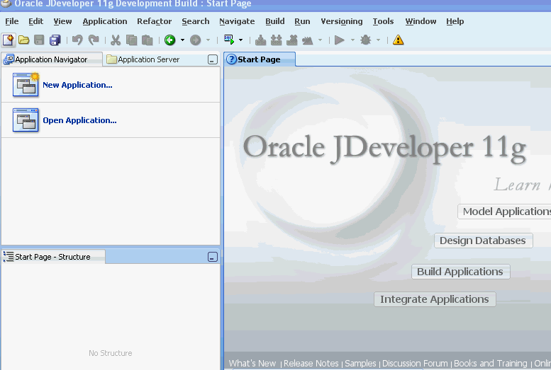
Figure 4-1 shows how Oracle JDeveloper appears the first time you access it.
-
Create a new SOA composite application, as described in Table 4-1.
Table 4-1 SOA Composite Application Creation
If Oracle JDeveloper... Then... Has no applications
For example, you are opening Oracle JDeveloper for the first time.
In the Application Navigator in the upper left, click New Application > SOA Application.
Has existing applications
From the File main menu:
-
Select New > Applications > SOA Application.
-
Click OK.
From the Application menu:
-
Select New > Applications > SOA Application.
-
Click OK.
This starts the Create SOA Application wizard.
-
-
Enter the values shown in Table 4-2:
Table 4-2 SOA Composite Application Creation Values
Field Value Application Name
Enter an application name (for this example,
MySOAApplicationis entered).Directory Name
Accept the default value or enter a different directory path.
Notes:
-
On a UNIX operating system, it is highly recommended that you enable Unicode support by setting the
LANGandLC_Allenvironment variables to a locale with the UTF-8 character set. This action enables the operating system to process any character in Unicode. SOA technologies are based on Unicode. If the operating system is configured to use non-UTF-8 encoding, SOA components may function in an unexpected way. For example, a non-ASCII file name can make the file inaccessible and cause an error. Oracle does not support problems caused by operating system constraints.In a design-time environment, if you are using Oracle JDeveloper, select Tools > Preferences > Environment > Encoding > UTF-8 to enable Unicode support. This is also applicable for runtime environments.
-
Do not create applications and projects in directory paths that have spaces (for example,
c:\Program Files).
-
-
Accept the default values for all remaining settings, and click Next.
The Project Name page of the Create SOA Application wizard appears.
-
Enter a name for the project (for this example,
MySOAProject), and click Next. Note that SOA is automatically selected as the project technology to use.Note:
Composite and component names cannot exceed 500 characters.A project deployed to the same infrastructure must have a unique name across SOA composite applications. This is because the uniqueness of a composite is determined by its project name. For example, do not perform the actions described in Table 4-3. During deployment, the second deployed project (composite) overwrites the first deployed project (composite).
Table 4-3 Restrictions on Naming an SOA Project
Create an Application Named... With an SOA Project Named... Application1Project1Application2Project1The Project SOA Settings page of the Create SOA Application wizard appears.
-
Select Empty Composite, and click Finish.
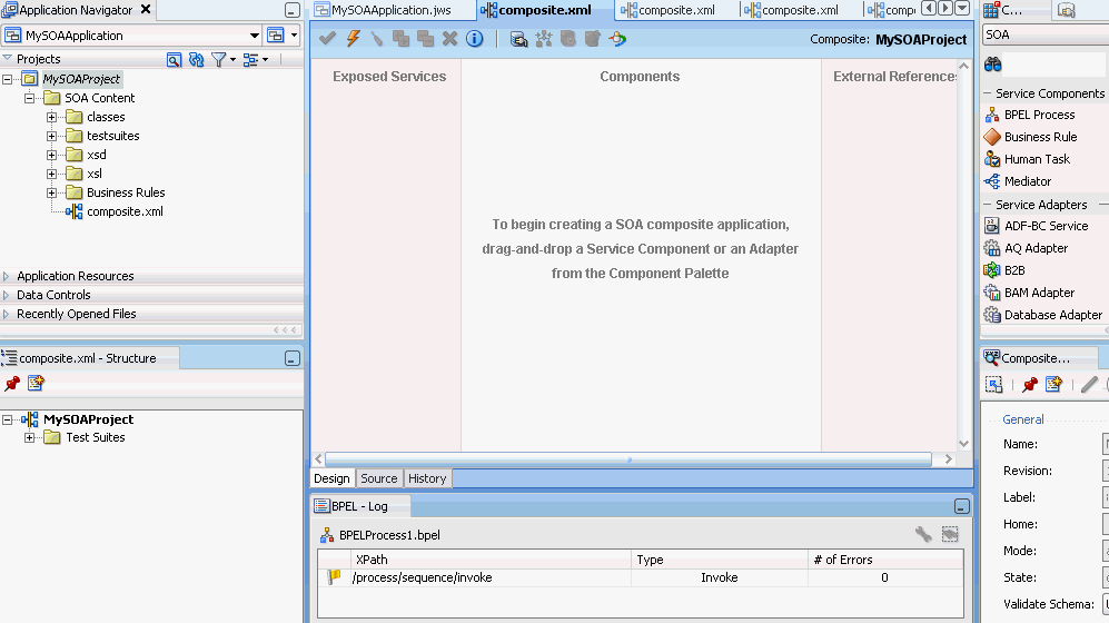
The SOA Composite Editor shown in Figure 4-2 appears. The composite.xml file displays in the Application Navigator. This file is automatically created when you create a project. This file describes the entire composite assembly of services, service components, and references. There is one composite.xml file per SOA project.
For more information about the sections of the SOA Composite Editor, see Section 2.1, "Introduction to the SOA Composite Editor."
-
Select Save All from the File main menu.
4.2.2 How to Add a Service Component
You create service components that implement the business logic or processing rules of your application.
You drag service components into the designer to invoke the initial property editor. This action enables you to define the service interface (and, for asynchronous BPEL processes, an optional callback interface).
Table 4-4 describes the available service components.
Table 4-4 Starting Service Component Editors
| Dragging This Service Component... | Invokes The... |
|---|---|
|
BPEL Process |
Create BPEL Process dialog: Enables you to create a BPEL process that integrates a series of business activities and services into an end-to-end process flow. |
|
Business Rule |
Create Business Rules dialog: Enables you to create a business decision based on rules. |
|
Human Task |
Create Human Task dialog: Enables you to create a workflow that describes the tasks for users or groups to perform as part of an end-to-end business process flow. |
|
Mediator |
Create Mediator dialog: Enables you to define services that perform message and event routing, filtering, and transformations. |
The following example describes the procedures to perform when a BPEL process is dragged into the designer.
-
From the Component Palette, select SOA.
-
From the Service Components list, drag a BPEL Process into the designer.
The Create BPEL Process dialog appears.
-
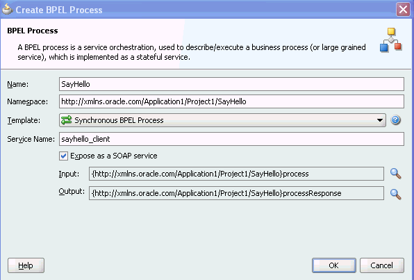
Enter the details shown in Table 4-5.
Table 4-5 Create BPEL Process Dialog Fields and Values
Field Value Name
Enter a name (for this example,
SayHellois entered).Namespace
Accept the default value.
Template
Select Synchronous BPEL Process.
For more information about available templates, see the online help.
Expose as a SOAP Service
Deselect this checkbox. This creates a standalone BPEL process. If you select this checkbox, a BPEL process and inbound web service binding component are each created and connected.
When complete, the Create BPEL Process dialog appears as shown in Figure 4-3.
-
Note that the Input and Output fields also appear in the Create BPEL Process dialog. These fields enable you to select or import specific input and output schemas from the Type Chooser dialog or SOA Resource Browser dialog, respectively. For this example, the default schemas are used, which consist of string input and output values. This schema defines the structure of the message to submit.
The SOA Resource Browser dialog also provides access to the Resource Palette, which provides a single dialog from which to share and access schemas in multiple applications.
-
Accept the default values for all remaining settings.
-
Click OK.
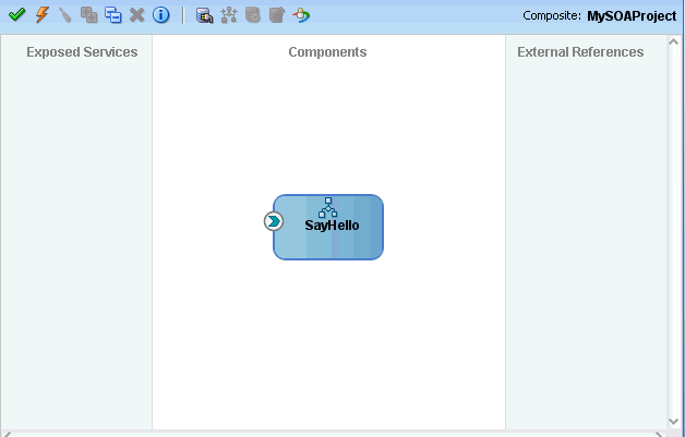
The BPEL process displays in the designer shown in Figure 4-4. The single arrow in a circle indicates that this is a synchronous, one-way BPEL process service component. An asynchronous process is indicated by two arrows in a circle, with each pointing in the opposite direction. The two arrows represent an interface and callback interface.
You can more fully define the content of your BPEL process now or at a later time. For this top-down example, the content is defined now.
-
Select Save All from the File main menu.
4.2.3 What You May Need to Know About Adding and Deleting a Service Component
Note the following details about adding service components:
-
A service component can be created from either the SOA Composite Editor or the designer of another component. For example, you can create a human task component from the SOA Composite Editor or the Oracle BPEL Designer.
-
The Resource Palette can be used to browse for service components defined in the SOA Composite Editor, and those deployed. A reference and wire are created when a service component from the SOA Composite Editor or from the deployed list is used.
Note the following details about deleting service components:
-
You can delete a service component by right-clicking it and selecting Delete from the context menu.
-
When a service component is deleted, all references pointing to it are invalidated and all wires are removed. The service component is also removed from the Application Navigator.
-
A service component created from within another service component can be deleted. For example, a human task created within the BPEL process service component of Oracle JDeveloper can be deleted from the SOA Composite Editor. In addition, the partner link to the task can be deleted. Deleting the partner link removes the reference interface from its
.componentTypefile and removes the wire to the task.
4.2.4 How to Edit a Service Component
To define specific details about the service component, you double-click the service component to display the appropriate editor, as described in Table 4-6.
Table 4-6 Starting SOA Service Component Wizards and Dialogs
| Double-Clicking This Service Component... | Displays The... |
|---|---|
|
BPEL Process |
Oracle BPEL Designer for further designing. |
|
Business Rule |
Business Rules Designer for further designing. |
|
Human Task |
Human Task Editor for further designing. |
|
Mediator |
Oracle Mediator Editor for further designing. |
-
Double-click the SayHello BPEL process.
This opens the BPEL process in editing.
To return to the SOA Composite Editor from within any service component, click Go to Composite Editor on the tool bar. You can also double-click composite.xml in the Application Navigator or single-click composite.xml above the designer.
-
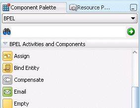
Go to the Component Palette in the upper right, as shown in Figure 4-5.
-
Drag an Assign activity into the designer beneath the receiveInput receive activity.
-
Double-click the Assign activity.
-
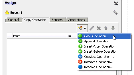
Click the Copy Operation tab.
-
From the dropdown list shown in Figure 4-6, select Copy Operation.
-
Enter appropriate details. For this example, the details shown in Table 4-7 are entered.
Table 4-7 Copy Operation Dialog Fields and Values
Field Value From
-
Type
Expression
-
Variables
concat('Hello ',bpws:getVariableData('inputVariable','payload','/client:SayHelloProcessRequest/client:input'))
Note: Press Ctrl+Space to access the XPath Expression Builder. Scroll through the list of values that appears and double-click the value you want. As you enter information, a red underscore can appear. This indicates that you are being prompted for additional information. Either enter additional information, or press the Esc key and delete the trailing slash to complete the input of information.
To
-
Type
Variable
-
Variables
Expand and select Variables > Process > Variables > outputVariable > payload > client:SayHelloProcessResponse > client:result
-
-
Click OK to close the Create Copy Operation dialog and the Assign dialog.
-
In the Application Navigator, double-click composite.xml in or single-click composite.xml above the designer.
This returns you to the SOA Composite Editor.
-
Select Save All from the File main menu.
4.2.5 How to Add a Service
You add a service binding component to act as the entry point to the SOA composite application from the outside world.
You drag services into the left swim lane to invoke an initial property editor. This action enables you to define the service interface.
Table 4-8 describes the available services.
| Dragging This Service... | Invokes The... |
|---|---|
|
Web service |
Create Web Service dialog: Creates a web invocation service. |
|
Adapters |
Adapter Configuration Wizard: Guides you through integration of the service with database tables, database queues, file systems, FTP servers, Java Message Services (JMS), IBM WebSphere MQ, BAM servers, sockets, or Oracle E-Business Suite applications. |
|
ADF-BC Service |
Create ADF-BC Service dialog: Creates a service data object (SDO) invocation service. |
|
B2B |
B2B Wizard: Guides you through selection of a document definition. |
|
EJB Service |
Create EJB Service: Creates an Enterprise JavaBeans service for using SDO parameters with Enterprise JavaBeans. |
The following example describes the procedures to perform when a web service is dragged into the designer.
Notes:
-
This section describes how to manually create a service binding component. You can also automatically create a service binding component by selecting Expose as a SOAP Service when you create a service component. This selection creates an inbound web service binding component that is automatically connected to your BPEL process, human task service, or Oracle Mediator component.
-
You cannot invoke a representational state transfer (REST) service from the SOA Composite Editor.
-
In the Component Palette, select SOA.
-
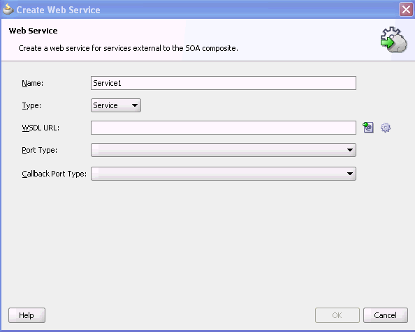
Drag a Web Service to the left swim lane.
This invokes the Create Web Service dialog shown in Figure 4-7.
-
Enter the details shown in Table 4-9:
Table 4-9 Create Web Service Dialog Fields and Values
Field Value Name
Enter a name for the service (for this example,
Service1is entered).Type
Select the type (message direction) for the web service. Since you dragged the web service to the left swim lane, the Service type is the correct selection, and displays by default:
-
Creates a web service to provide an entry point to the SOA composite application
-
Creates a web service to provide access to an external service in the outside world
Since this example describes how to create an entry point to the SOA composite application, Service is selected.
-
-
Select the WSDL file for the service. There are three methods for selection:
-
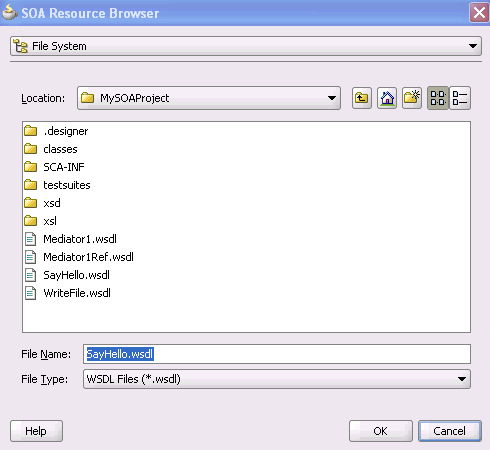
To the right of the WSDL URL field, click the first icon and select an existing WSDL file from the local file system (for this example, SayHello.wsdl is selected). Note that File System in the list at the top of the dialog is automatically selected. Figure 4-8 provides details.
-
To the right of the WSDL URL field, click the first icon and select Resource Palette from the list at the top of the dialog, as shown in Figure 4-9. This action enables you to use existing WSDL files from other applications.
Figure 4-9 Use of Existing WSDL files from Other Applications
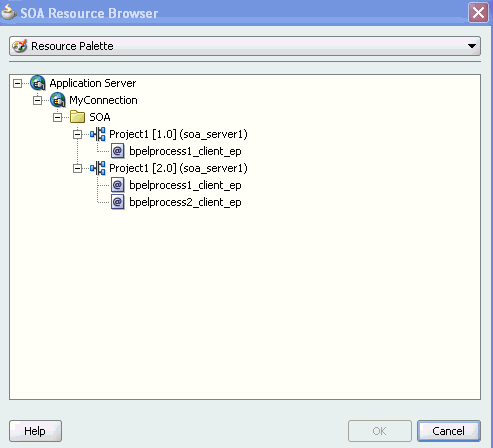
Description of "Figure 4-9 Use of Existing WSDL files from Other Applications"
-
To the right of the WSDL URL field, click the second icon to automatically generate a WSDL file from a schema. Figure 4-10 shows the Create WSDL dialog.
Figure 4-10 Automatic Generation of WSDL File
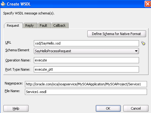
Description of "Figure 4-10 Automatic Generation of WSDL File"
-
-
Click OK to return to the Create Web Service dialog.
-
Note the additional details described in Table 4-10:
-
Click OK.
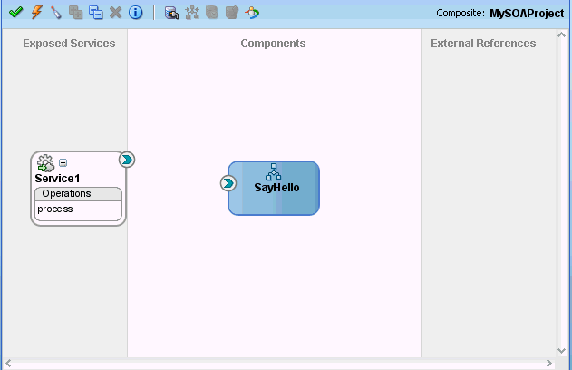
The SOA composite application now looks as shown in Figure 4-11. The service deploys in the left swimlane.
-
From the File main menu, select Save All.
Note:
WSDL namespaces must be unique. Do not just copy and rename a WSDL. Ensure that you also change the namespaces.After initially creating a service, you can edit its contents at a later time. Double-click the component icon to display its appropriate editor or wizard. Table 4-11 provides an overview.
4.2.6 What You May Need to Know About Adding and Deleting Services
Note the following detail about adding services:
-
When a new service is added for a service component, the service component is notified so that it can make appropriate metadata changes. For example, when a new service is added to a BPEL service component, the BPEL service component is notified to create a partner link that can be connected to a receive or an on-message activity.
Note the following detail about deleting services:
-
When a service provided by a service component is deleted, all references to that service component are invalidated and the wires removed.
4.2.7 What You May Need to Know About WSDL References
A WSDL file is added to the SOA composite application whenever you create a new component that has a WSDL (for example, a service binding component, service component (for example, Oracle Mediator, BPEL process, and so on), or reference binding component. When you delete a component, any WSDL imports used by that component are removed only if not used by another component. The WSDL import is always removed when the last component that uses it is deleted.
When a service or reference binding component is updated to use a new WSDL, it is handled as if the interface was deleted and a new one was added. Therefore, the old WSDL import is only removed if it is not used by another component.
If a service or reference binding component is updated to use the same WSDL (porttype qname), but from a new location, the WSDL import and any other WSDL reference (for example, the BPEL process WSDL that imports an external reference WSDL) are automatically updated to reference the new location.
Simply changing the WSDL location on the source view of the composite.xml file's import is not sufficient. Other WSDL references in the metadata are required by the user interface (see the ui:wsdlLocation attribute on composite and componentType services and references). There can also be other WSDL references required by runtime (for example, a WSDL that imports another WSDL, such as the BPEL process WSDL).
Always modify the WSDL location though the dialogs of the SOA Composite Editor in which a WSDL location is specified (for example, a web service, BPEL partner link, and so on). Changing the URL's host address is the exact case in which the SOA Composite Editor automatically updates all WSDL references.
4.2.8 What You May Need to Know About Invoking the Default Revision of a Composite
A WSDL URL that does not contain a revision number is processed by the default composite application. This action enables you to always call the default revision of the called service without having to make other changes in the calling composite.
If you want your WSDL to be processed by the default composite application, but the WSDL URL includes a revision number, you can manually remove it.
Not doing so results in the hard-coded references of the revision number of the service being called in the calling composite. This binds it to always call that particular revision even if the default revision of the called service changes after deployment.
-
In the SOA Composite Editor, double-click the reference binding component that contains the WSDL revision number to remove.
The Update Reference dialog appears.
-
Click the icon to the right of the WSDL URL field.
The SOA Resource Browser dialog appears.
-
Select Resource Palette from the list at the top of the dialog.
-
Expand the nodes under the appropriate application server connection to list all deployed composites and revisions.
-
Select the appropriate endpoint and click OK.
Your selection displays in the WSDL URL field.
-
Remove everything between the
!and/symbols. For example, assume the revision number is3.0. Change:http://pdent12.us.oracle.com:8001/soa-infra/services/default/ VersionedComposite!3.0*e295c89a-b198-4835-ab16-a3a250d3b46c/ Mediator1_ep?WSDLto:
http://pdent12.us.oracle.com:8001/soainfra/services/default/
VersionedComposite/Mediator1_ep?WSDL
The WSDL reloads.
-
Select port types appropriate to your environment.
-
Click OK.
This action enables your WSDL file to be processed by the default composite application.
4.2.9 How to Wire a Service and a Service Component
You wire (connect) the web service and BPEL process service component. Note the following:
-
Since the web service is an inbound service, a reference handle displays on the right side. Web services that are outbound references do not have a reference handle on the right side.
-
You can drag a defined interface to an undefined interface in either direction (reference to service or service to reference). The undefined interface then inherits the defined interface. There are several exceptions to this rule:
-
A component has the right to reject a new interface. For example, a mediator can only have one inbound service. Therefore, it rejects attempts to create a second service.
-
You cannot drag an outbound service (external reference) to a business rule because business rules do not support references. When dragging a wire, the user interface highlights the interfaces that are valid targets.
-
-
You cannot wire services and composites that have different interfaces. For example, you cannot connect a web service configured with a synchronous WSDL file to an asynchronous BPEL process. Figure 4-12 provides details.
Figure 4-12 Limitations on Wiring Services and Composites with Different Interfaces
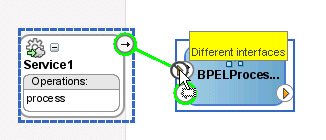
Description of "Figure 4-12 Limitations on Wiring Services and Composites with Different Interfaces"
The service and reference must match, meaning the interface and the callback must be the same. If you have two services that have different interfaces, you can place a mediator between the two services and perform a transformation between the interfaces.
To wire a service and a service component:
-
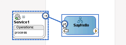
From the Service1 reference handle, drag a wire to the SayHello BPEL process interface, as shown in Figure 4-13.
-
Create additional service components and wire them, as needed.
For more information about
composite.xmlfile contents, see Section 4.2.11, "How to Add a Reference." -
Select Save All from the File main menu.
4.2.10 What You May Need to Know About Adding and Deleting Wires
Note the following details about adding wires:
-
A service component can be wired to another service component if its reference matches the service of the target service component. Note that the match implies the same interface and callback interface.
-
Adding the following wiring between two mediator service components causes an infinite loop:
-
Create a business event.
-
Create a mediator service component and subscribe to the event.
-
Create a second mediator service component to publish the same event.
-
Wire the first mediator to the second mediator component service.
If you remove the wire between the two mediators, then for every message, the second mediator can publish the event once and the first mediator can subscribe to it.
-
Note the following details about deleting wires:
-
When a wire is deleted, the component's outbound reference is automatically deleted and the component is notified so that it can clean up (delete the partner link, clear routing rules, and so on). However, the component's interface is never deleted. All Oracle SOA Suite services are defined by their WSDL interface. When a component's interface is defined, there is no automatic deletion of the service interface in the SOA Composite Editor.
If you want to change the service WSDL interface, there are several workarounds:
-
In most cases, you just want to change the schema instead of the inbound service definition. In the SOA Composite Editor, click any interface icon that uses the WSDL. For example, you can click the web service interface icon or the Oracle Mediator service icon. This invokes the Update Interface dialog, which enables you to change the schema for any WSDL message.
-
If you are using an Oracle Mediator service component, the Refresh operations from WSDL icon of the Oracle Mediator Editor enables you to refresh (after adding new operations) or replace the Oracle Mediator WSDL. However, you are warned if the current operations are to be deleted. If you change the WSDL to the new inbound service WSDL using this icon, the wire typically breaks because the interface has changed. You can then wire Oracle Mediator to the new service.
-
In many cases, a new service requires a completely new Oracle Mediator. Delete the old Oracle Mediator, create a new one, and wire it to the new service.
-
If you are using a BPEL process service component, select a new WSDL through the Edit Partner Link dialog.
See Section 4.2.14, "How to Update Message Schemas of Components (Optional)" for details about the Update Interface dialog.
-
4.2.11 How to Add a Reference
You can add reference binding components that enable the SOA composite application to send messages to external services in the outside world.
You drag references into the right swim lane to invoke the initial property editor. This action enables you to define the service interface.
Table 4-12 describes the available references.
| Dragging This Service... | Invokes The... |
|---|---|
|
Web Service |
Create Web Service dialog: Creates a web invocation service. |
|
Adapters |
Adapter Configuration Wizard: Guides you through integration of the service with database tables, database queues, file systems, FTP servers, Java Message Services (JMS), IBM WebSphere MQ, BAM servers, sockets, or Oracle E-Business Suite applications. |
|
ADF-BC Service |
Create ADF-BC Service dialog: Creates a service data object (SDO) invocation service. |
|
B2B |
B2B Wizard: Guides you through selection of a document definition. |
|
EJB Service |
Create EJB Service dialog: Creates an Enterprise JavaBeans service for using SDO parameters with Enterprise JavaBeans. |
The following example describes the procedures to perform when a file adapter is dragged into the designer.
-
In the Component Palette, select SOA.
-
Drag a File Adapter to the right swim lane.
This launches the Adapter Configuration wizard.
-
Provide appropriate responses to the dialogs that appear. For example, to configure the file adapter to write to a file in a directory, you are prompted to:
-
Select to write to a file.
-
Specify the directory in which to write the outgoing file.
-
Specify the schema file location.
When complete, the designer looks as shown in Figure 4-14:
Figure 4-14 Design Completion of SOA Composite Application
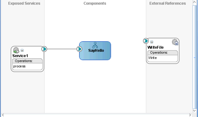
Description of "Figure 4-14 Design Completion of SOA Composite Application"
For more information about how creating partner links within a BPEL process service component impacts how partner links display in the SOA Composite Editor, see Section 5.4, "Creating a Partner Link."
-
-
Double-click the SayHello BPEL process.
-
Complete the remaining portions of the BPEL process design:
-
Create an invoke activity to invoke the partner link
-
Create a variable
-
Assign a return value to the variable
-
-
Select Save All from the File main menu.
After initially creating a reference, you can edit its contents at a later time. Double-click the component icon to display its appropriate editor or wizard. See Table 4-11 for an overview.
4.2.12 What You May Need to Know About Adding and Deleting References
Note the following detail about adding references:
-
The only way to add a new reference in the SOA Composite Editor is by wiring the service component to the necessary target service component. When a new reference is added, the service component is notified so it can make appropriate changes to its metadata. For example, when a reference is added to a BPEL service component, the BPEL service component is notified to add a partner link that can then be used in an invoke activity.
Note the following details about deleting references:
-
When a reference for a service component is deleted, the associated wire is also deleted and the service component is notified so it can update its metadata. For example, when a reference is deleted from a BPEL service component, the service component is notified to delete the partner link in its BPEL metadata.
-
Deleting a reference connected to a wire clears the reference and the wire.
4.2.13 How to Wire a Service Component and a Reference
You now wire (connect) the BPEL process and the file adapter reference.
To wire a service component and a reference:
-
In the Application Navigator, double-click composite.xml or single-click composite.xml above the designer.
-
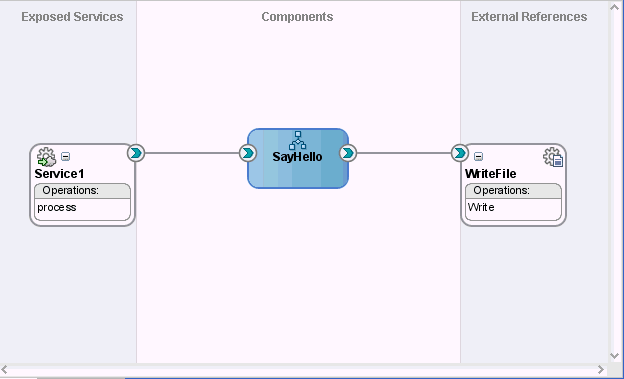
From the SayHello BPEL process, drag a wire to the WriteFile reference, as shown in Figure 4-15.
Figure 4-15 Wiring of a Service Component and Reference
Description of "Figure 4-15 Wiring of a Service Component and Reference"
-
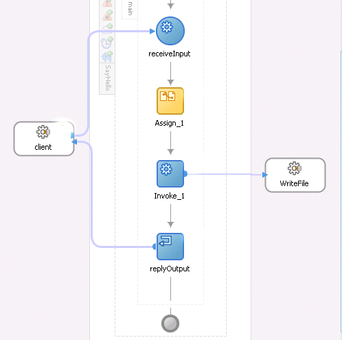
Double-click the SayHello BPEL process and note that the WriteFile reference displays as a partner link in the right swim lane, as shown in Figure 4-16.
Figure 4-16 Display of the Reference as a Partner Link in the BPEL Process
Description of "Figure 4-16 Display of the Reference as a Partner Link in the BPEL Process"
-
Select Save All from the File main menu.
-
In the Application Navigator, select the composite.xml file.
-
Click the Source tab to review what you have created.
The
Service1service shown in Example 4-1 provides the entry point to the composite.<composite name="MySOAProject"> . . . . . . <service name="Service1" ui:wsdlLocation="SayHello.wsdl"> <interface.wsdl interface="http://xmlns.oracle.com/MySOAApplication/ MySOAProject/ SayHello#wsdl.interface(SayHello)"/> <binding.ws port="http://xmlns.oracle.com/MySOAApplication/MySOAProject/ SayHello#wsdl.endpoint (sayhello_client_ep/SayHello_pt)"/> </service>The
SayHelloBPEL process service component is shown in Example 4-2:<component name="SayHello"> <implementation.bpel src="SayHello.bpel"/> </component>A reference binding component named
WriteFileis shown in Example 4-3. This reference type is a JCA file adapter. The reference provides access to the external service in the outside world.<reference name="WriteFile" ui:wsdlLocation="WriteFile.wsdl"> <interface.wsdl interface="http://xmlns.oracle.com/pcbpel/adapter/ file/MySOAApplication/MySOAProject/WriteFile%2F#wsdl.interface(Write_ptt)"/> <binding.jca config="WriteFile_file.jca"/> </reference>In Example 4-4, the communication (or wiring) between service components is described:
-
The source
Service1web service is wired to the targetSayHelloBPEL process service component. Wiring enables web service message communication with this specific BPEL process. -
The source
SayHelloBPEL process is wired to the targetWriteFilereference binding component. This is the reference to the external service in the outside world.
-
4.2.14 How to Update Message Schemas of Components (Optional)
You can update the message schemas used by service components or binding components.
To update message schemas of components:
-
Double-click an interface handle of a component, as shown in Figure 4-17. For this example, the inbound interface handle of the SayHello BPEL process service component is selected.
Figure 4-17 Selection of Inbound Interface Handle

Description of "Figure 4-17 Selection of Inbound Interface Handle"
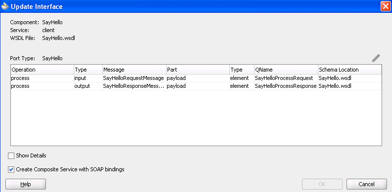
The Update Interface dialog shown in Figure 4-18 appears. This dialog shows all schemas used by the interface's WSDL and enables you to choose a new schema for a selected message part.
-
Use one of the following methods to select the message schema to update:
-
Double-click the message schema row.
-
Select a row and click the Update icon in the upper right corner above the table.
The Type Chooser dialog appears.
-
-
Select a new schema element, and click OK.
-
In the Update Interface dialog, click OK. This updates the interface WSDL to use the new schemas.
4.2.15 What You May Need to Know About Updating Message Schemas of Components
Note the following details about updating message schemas of components:
-
It is possible that several operations (or an input and an output) can use the same WSDL message. In this case, the same message is seen in multiple rows of the table. If you update the schema in one row, the change appears in the other rows.
-
When the schema used by an interface is changed, it may invalidate previously configured features within a component that depend on the schema. For example, a transformation step in a BPEL process or mediator service component may be invalid because it is using a transformation map created for the old schema.
-
If the interface does not have a callback (as is the case for the BPEL process in this example), the Update Interface dialog does show a Callback Port Type table.
-
Since multiple interfaces can be defined by the same WSDL, the modification to one interaction (WSDL) also modifies the other interfaces.
-
When you select Show Details, the table shows fully qualified names and complete file paths.
-
When the interface belongs to a service component (and not a service binding component or reference), the Create Composite Service with SOAP bindings checkbox appears. This checkbox provides the same functionality as the Expose as a SOAP Service checkbox on the BPEL process and human task creation dialogs. If you check this box and click OK, a service and wire are automatically generated. If it is checked (service exists) and you deselect it and click OK, the service and wire are deleted.
4.2.16 How to Invoke Other Composites
You can invoke other SOA composite applications from your SOA composite application. The other applications must be deployed.
-
Create a web service or partner link through one of the following methods.
-
In the SOA Composite Editor, drag a Web Service from the Component Palette to the External References swim lane.
-
In Oracle BPEL Designer, drag a Partner Link from the Component Palette to the right swim lane.
-
-
Access the SOA Resource Browser dialog based on the type of service you created.
-
For the Create Web Service dialog, click the Find existing WSDLs icon.
-
For the Edit Partner Link dialog, click the SOA Resource Browser icon.
-
-
From the list at the top, select Resource Palette.
-
Expand the tree to display the application server connection to the Oracle WebLogic Administration Server on which the SOA composite application is deployed. For this example, MyConnection).
-
Expand the application server connection.
-
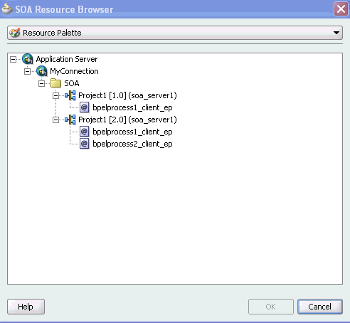
Expand the SOA composite applications. Figure 4-19 provides details.
Figure 4-19 Browse for an SOA Composite Application
Description of "Figure 4-19 Browse for an SOA Composite Application"
-
Select the composite service, as shown in Figure 4-20.
-
Click OK.
4.2.17 How to Deploy the SOA Composite Application
Deploying the SOA composite application involves creating and deploying an archive of the SOA composite application. For more information, see Chapter 43, "Deploying SOA Composite Applications."
4.2.18 How to Manage Deployed Composites
You can manage deployed SOA composite applications from the Application Server Navigator in Oracle JDeveloper. Management tasks consist of deploying, undeploying, activating, retiring, turning on, and turning off SOA composite application revisions.
Note:
These instructions assume you have created an application server connection to an Oracle WebLogic Administration Server on which the SOA Infrastructure is deployed. Creating a connection to an Oracle WebLogic Administration Server enables you to browse for managed Oracle WebLogic Servers or clustered Oracle WebLogic Servers in the same domain. From the File main menu, select New > Connections > Application Server Connection to create a connection.-
From the View main menu, select Application Server Navigator.
-
Expand your connection name (for this example, named myConnection).
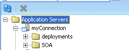
The deployments and SOA folders appear, as shown in Figure 4-21. The SOA folder displays all deployed SOA composite application revisions and services. You can browse all applications deployed on all Oracle WebLogic Administration Servers, managed Oracle WebLogic Servers, and clustered Oracle WebLogic Servers in the same domain. Figure 4-21 provides details.
-
Expand the SOA folder.
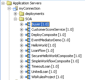
Deployed SOA composite applications and services appear, as shown in Figure 4-22.
Figure 4-22 Deployed SOA Composite Applications
Description of "Figure 4-22 Deployed SOA Composite Applications"
-
Right-click a deployed SOA composite application.
-
Select an option to perform. The options that display for selection are based upon the current state of the application. Table 4-13 provides details.
Table 4-13 SOA Composite Application Options
-
If you want to deploy a prebuilt SOA composite application archive that includes a deployment profile, right-click the SOA folder and select Deploy SOA Archive. The archive consists of a JAR file of a single application or an SOA bundle ZIP file containing multiple applications.
You are prompted to select the following:
-
The target SOA servers to which you want to deploy the SOA composite application archive.
-
The archive to deploy.
-
The configuration plan to attach to the application. As you move projects from one environment to another (for example, from testing to production), you typically must modify several environment-specific values, such as JDBC connection strings, hostnames of various servers, and so on. Configuration plans enable you to modify these values using a single text (XML) file called a configuration plan. The configuration plan is created in either Oracle JDeveloper or from the command line. During process deployment, the configuration plan is used to search the SOA project for values that must be replaced to adapt the project to the next target environment. This is an optional selection.
-
Whether you want to overwrite an existing composite of the same revision ID. This action enables you to redeploy an application revision.
-
For more information, see the following documentation:
-
Chapter 43, "Deploying SOA Composite Applications" for details about creating a deployment profile and a configuration plan and deploying an existing SOA archive
-
Oracle Fusion Middleware Administrator's Guide for Oracle SOA Suite for details about managing deployed SOA composite applications from Oracle Enterprise Manager Fusion Middleware Control Console
4.2.19 How to Test the SOA Composite Application
You can run and test instances of deployed SOA composite applications from Oracle Enterprise Manager Grid Control Console. For more information about testing an SOA composite application, see Oracle Fusion Middleware Administrator's Guide for Oracle SOA Suite.
