


|

|
|
|
|
Building Format Definitions
You can build and modify format definitions using one of the following methods:
Note: You must use the Formatter interface when using output operations or mapping format fields.
This section describes the following topics:
Using MsgDefAdmin to Build Definitions
The MsgDefAdmin importer utility is an interpreter for four commands that let you add, retrieve, delete, and list message format definitions that are stored in the iiDatabase. MsgDefAdmin allows you to define message formats in an XML language called Message Definition Format Language (MFL). You can then import these textual descriptions into the iiDatabase. Message definitions that exist within the iiDatabase can also be listed, retrieved, or deleted using this utility.
Creating and Storing MFL Documents
An MFL document is a description of a message that is sent to an application. To create an MFL document, you need to translate messages into a textual description that conforms to the MFL document type definition (mfl.dtd). mfl.dtd defines valid elements and attributes necessary to create message formats. The attributes in mfl.dtd are the same ones that you can define using Formatter. Refer to MFL Document Type Definition for a listing of mfl.dtd and an example MFL document.
As an example, suppose you are integrating a payroll application. This payroll application uses a message that has the following structure:
NUM_EMPLOYEES 4-byte Little Endian integer
EMPLOYEE_REC Employee record
EMPLOYEE_NAME 32 characters
EMPLOYEE_SSN 11 characters
EMPLOYEE_PAY 15 bytes of Packed Decimal
Listing 3-1 is an example instance of payroll data that contains data for one employee. In the example, binary data is represented with a \x prefix to indicate that it is hexadecimal. This is done for illustration purposes only.
Listing 3-1 Instance of Payroll Data
\x01\x00\x00\x00JohnDoe\xFF......11122333300000000000000000000000063125F
You can create an MFL document for the payroll application by using the steps described in the following procedure.
<?xml version='1.0'?>
<!DOCTYPE MessageFormat SYSTEM `mfl.dtd'>
<?xml version='1.0'?>
<!DOCTYPE MessageFormat SYSTEM `mfl.dtd'>
<MessageFormat name='PAYROLL_MSG'>
<?xml version='1.0'?>
<!DOCTYPE MessageFormat SYSTEM `mfl.dtd'>
<MessageFormat name='PAYROLL_MSG'>
<FieldFormat name='NUM_EMPLOYEES'
type='LittleEndian4'/>
<?xml version='1.0'?>
<!DOCTYPE MessageFormat SYSTEM `mfl.dtd'>
<MessageFormat name='PAYROLL_MSG'>
<FieldFormat name='NUM_EMPLOYEES'
type='LittleEndian4'/>
<StructFormat name='EMPLOYEE_REC'
repeatField="NUM_EMPLOYEES">
<?xml version='1.0'?>
<!DOCTYPE MessageFormat SYSTEM `mfl.dtd'>
<MessageFormat name='PAYROLL_MSG'>
<FieldFormat name='NUM_EMPLOYEES'
type='LittleEndian4'/>
<StructFormat name='EMPLOYEE_REC'
repeatField="NUM_EMPLOYEES">
<FieldFormat name='EMPLOYEE_NAME' type='String'
delim='\xFF'/>
<FieldFormat name='EMPLOYEE_SSN' type='String'
length='11'/>
<FieldFormat name='EMPLOYEE_PAY' type='Upacked'
length='15'/>
<?xml version='1.0'?>
<!DOCTYPE MessageFormat SYSTEM `mfl.dtd'>
<MessageFormat name='PAYROLL_MSG'>
<FieldFormat name='NUM_EMPLOYEES' type='LittleEndian4'/>
<StructFormat name='EMPLOYEE_REC'
repeatField="NUM_EMPLOYEES">
<FieldFormat name='EMPLOYEE_NAME' type='String'
delim='\xFF'/>
<FieldFormat name='EMPLOYEE_SSN' type='String'
length='11'/>
<FieldFormat name='EMPLOYEE_PAY' type='Upacked'
length='15'/>
</StructFormat>
</MessageFormat>
Listing 3-2 MsgDefAdmin
- Copyright (c) 2000 BEA Systems, Inc.
All Rights Reserved.
Distributed under license by BEA Systems, Inc.
BEA eLink Information Integrator is a registered trademark.
This product includes software developed by the Apache Software Foundation (http://www.apache.org/).
- - - BEA eLink Information Integrator 1.0 - - -
- - - Message Definition Importer Tool - - -
Enter choice:
1) Add Message Definition
2) Get Message Definition
3) Delete Message Definition
4) List Message Definitions
Q) Quit >
Running MsgDefAdmin with command-line options
The MsgDefAdmin utility also supports execution in a non-interactive mode. Two command-line options are supported that allow you to import or export message definitions.
The MsgDefAdmin utility has the following command-line syntax:
MsgDefAdmin [-i | -e] <XML filename>
where
Processing file: payroll.xml
Message Definition created!
Processing file: employee_data.xml
Message Definition created!
Processing file: purchase_order.xml
Message Definition created!
XML Document retrieved:
Created file PAYROLL_MSG.xml
ML Document retrieved: Created file EMPLOYEE.xml
Converting Data Integration Option Formats to MFL
Information Integrator provides a utility called fgf2mfl to convert Data Integration Option FML group formats and meta-type information formats to MFL.
The fgf2mfl utility has the following syntax:
fgf2mfl [-f | -m] <filename>
where
If you invoke fgf2mfl without specifying a flag, fgf2mfl attempts to determine the file type from the filename extension. For example, an extension of .fgf specifies an FML group format, and an extension of .mti specifies a meta type format.
Starting Formatter
You can launch the Formatter interface using the steps described in the following procedure.
Note: If you do not have an assigned user ID and password, ask your system administrator to create them for you.
Figure 3-1 Formatter Logon
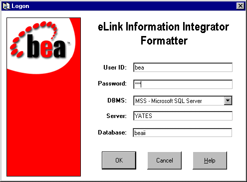
Figure 3-2 Formatter Main Window
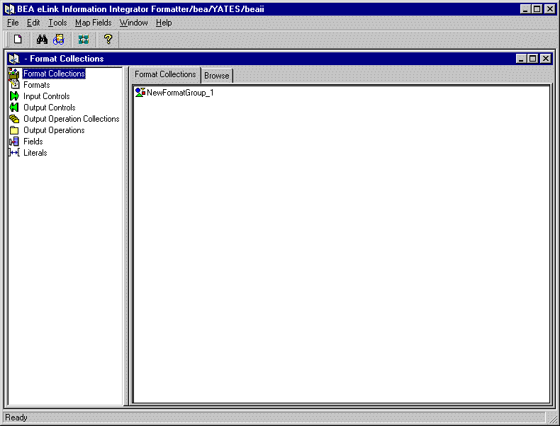
The Formatter is divided into two panes. Format components are displayed in a hierarchical organization in the left pane. When you select a component in the left pane, the right pane of the window displays detailed information about the selected component. The detailed information is kept in property sheets labeled with tabs.
Using Formatter to Build Definitions
You can use the Formatter to edit or create message format definitions. If you want to create a message definition from scratch, follow the instructions in Using MsgDefAdmin to Build Definitions. However, you must use Formatter to specify the mapping of data between message formats and any output operations performed on data items.
Using the Formatter, a message format definition is defined as a series of components. These components describe how to parse each piece of information in the message, how to output each piece of information, and how each piece of information relates to the message as a whole.
These components include:
To define a message format definition using Formatter, you must define the components of the message using a bottoms up strategy. A high-level approach is described in the following procedure.
Literals
A literal is a string of characters that Formatter processes as:
Formatter uses literals in input controls, output controls, operations, format terminators, and repeating sequence terminators. Valid literals include the printable characters A-Z, a-z, 0-9, and any keyboard character available by pressing Shift with another printable character; hex values that can include printable and non printable characters. Do not use single quotes in literal names. When literals are used as pad characters, only the first character is used.
Note: The maximum character length of a literal is 127.
Creating a Literal
You can create a literal using the steps described in the following procedure.
Figure 3-3 Literal Property Sheet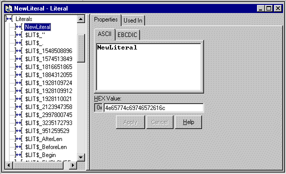
Note: The literal name must be 32 characters or less. Single quotes, double quotes, and spaces should not be used in names.
Note: You cannot drag and drop literals.
Fields
Fields are named items of message data and are the smallest possible container for information. In Formatter, the field name is the link between the input and output data. Each field can be used in multiple formats and associated with different input and output controls. To identify a field in a message, a combination of the field name and a control is used.
Note: Enter a unique name for each field. Field names can be up to 32 characters in length.
Creating a Field
Figure 3-4 Fields Property Sheet
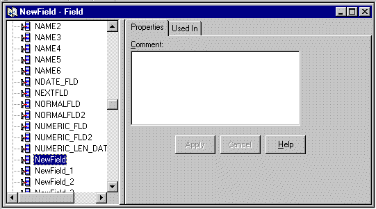
Note: The field name must be 32 characters or less. Field names with quotes may only have single or double quotes, not both. Field names with spaces or underscores must be enclosed by single or double quotes. A field with the name Field_1 could be used as "Field_1" or `Field_1' (but not "Field_1' or `Field_").
The Comment field does not retain formatted text when imported or exported. Using carriage returns in the Comment field is not recommended.
Note: You can change the name of a field by double-clicking on the field name. Type the new name and press Enter to enter the name and position it in the list.
Input Controls
To build input formats, you must build input controls. Input controls are used to parse input data. The iiServer uses input controls to determine how to find the beginning and end of the data in a field.
An input control also determines whether the data for a field is mandatory or optional. Mandatory means that Formatter considers the parse successful if the parse start and end strings are found, even if the associated data is empty. If the parse is successful, the field passes the mandatory test and the parse continues. If the parse parameters are not found, the field fails the mandatory test and the parse fails for the rest of the format. Optional means that the parse continues even if parse parameters for the field are not found.
Input controls can use tags to separate data. Tags are sets of bits or characters explicitly defining a string of data. For example, <NAME> could mark the beginning of a name field in a message.
After an input control is created, it can be saved as an output control. For more information, refer to Saving an Input Control to an Output Control.
Creating an Input Control
You can create an input control using the steps described in the following procedure.
Note: The input control name must be 32 characters or less. Single quotes, double quotes, and spaces should not be used in names. However, if using quotes, make sure they are not mismatched (for example, a single quote paired with a double quote).
Table 3-1 Input Control Type Values
Input Control Type Value Description Data Only Field has a data component only. Data is the value of the field. Tag and Data Field has a literal tag and data component (in this order). Tag-Length and Data Field has a tag, length, and data component (in this order). Length and Data Field has a length and data component (in this order). Repetition Count Field contains the count of a repeating component. Literal Field value is a literal. Length-Tag and Data Field has a length, tag, and data component (in this order). Regular Expression Compares input data to the value of the literal parse control using pattern matching. A regular expression requires an associated string data type and a literal value.
Minimum Length + Delimiter as your termination type. You also need to specify a delimiter from the Delimiter drop-down list.
Saving an Input Control to an Output Control
You can save input controls as output controls. The output controls mirror (as closely as possible) the contents of the input control. You may have to modify the output control because certain properties of input controls do not have exact matches on the output control side.
You can save an input control as an output control using the steps described in the following procedure.
For example, the first time the input control called Test is saved as an output control, it is saved as OFC_1_Test. The second time Test is saved, it is saved as OFC_2_Test, and so forth.
Output Controls
Output controls are used to format output data. iiServer uses output controls to determine how to justify and trim data, add prefixes or suffixes, or perform an arithmetic expression. Using the output control types of either Input Field Value = or Input Field Exists allows alternative output formatting. For more information on alternative output formatting, refer to Alternative Input and Output Formats.
The Output Control tab allows you to add a new output control, create and define default and length output operations, and assign case and justification operations to an output control.
Creating an Output Control
You can create an output control using the steps described in the following procedure.
Figure 3-5 Output Control Property Tab
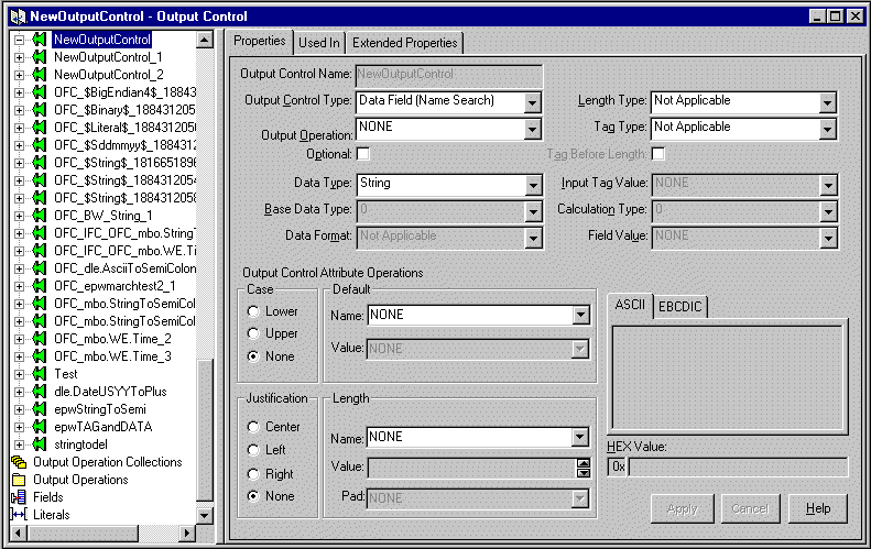
Note: The output control name must be 32 characters or less. Single quotes, double quotes, and spaces should not be used in names. However, if using quotes, make sure the quotes are not mismatched (for example, a single quote with a double quote).
The output control is highlighted and its name appears in the Output Control name text box in the Output Control tab.
Table 3-2 Output Control Types
Output Control Type Description Conditional Field Mark field as output only if existence check field exists. Data Field (Name Search) Map the output field to the input field by field name. Data Field (Tag Search) Map the output field to the input field by tag value. Existence Check Field Mark field as an existence check field. Input Field Exists An input field exists. Input Field Value = The input field's value equals a particular value. Literal Field value is a literal. Rules Field Output control is chosen based on rules evaluation.
An output control defines how you want iiServer to output a message field. Output Control types identify how to map to the input data and the type of reformatting to use. The Data Field (Name Search) and Data Field (Tag Search) values map the output field to the input field by either name or tag. Other output control types define details concerning data mapping.
By default, the output control is mandatory. Mandatory means Formatter should fail with an error message if the field was not found in the input message or the input field was NULL, and there was no data-producing operation associated with the output control.
Assigning and Defining Output Control Attribute Operations
The Output Control Attribute Operations section of the Properties tab allows you to assign existing or define new default and length output operations. You can also assign case and justification operations in this section. You cannot change existing operations from this section; however, you can change operations using the Extended Properties tab. See Using the Extended Properties Tab for more information.
The Output Control Attribute Operations section is shown in Figure 3-6.
Figure 3-6 Output Control Attribute Operations Section
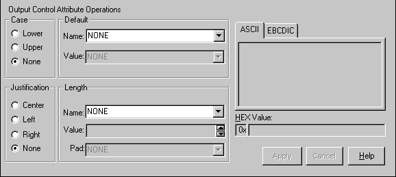
You can define new default or length output operations by using the steps described in the following procedure.
You can assign existing output operations by using the steps described in the following procedure.
Using the Extended Properties Tab
You can define and modify output operations and collections and assign them to an associated output control from the Extended Properties tab. If you select more than one output operation, a new output operation collection is created that begins with the name of the output control. If more than one output operation exists for a control, a number is appended to the name (for example, SS_1 for an output operation collection assigned to SS).
Selecting a case, justification, default, and length operation assigns them to a collection in the following order: default, case, length, and justify. This order is enforced by the initial assignment only.
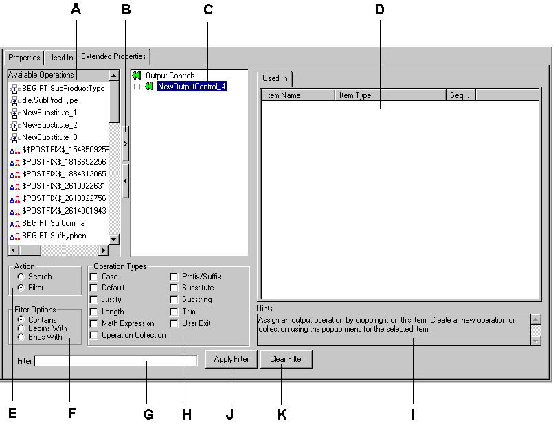
The sections of the Extended Properties tab are labeled in Figure 3-7 and described in Table 3-3.
Figure 3-7 Extended Properties Tab
|
Label |
Section |
Description |
|---|---|---|
|
A |
Available Operations |
Available output operations and output operation collections in read-only mode. This list can be filtered. You can select any or all of the items in this list and apply them to the output control by dragging and dropping the items onto the control. |
|
B |
Add (>) and Remove (<) Buttons |
The Add (< ) and Remove (>) buttons provide a fast way to perform specific tasks. The buttons behave differently, depending on what is selected. To assign operations to an output control, select the output control in the Formatter tree view, select the operations in the Available Operations list, and click >. To remove operations from an output control, select the output control in the Formatter tree view, select the operations in the Available Operations list, and click <. To remove an output operation or output operation collection, select it and click <. A confirmation box appears asking you to confirm the removal. |
|
C |
Selected Operations |
The Selected operations list is a tree view containing a duplication of the output control from the main tree view; however, functionality not available in the main tree view is available in this list. With a collection selected, you can reorder the sequence of output operations in the output operations collections tab. Pop-up menus are available allowing you to create, remove, open, expand, and collapse items. Creating a new item with an output control selected in the tree view assigns the new item to the control. If an output operation or output operation collection is selected, you can access the pop-up menu and select Duplicate. Caution: A change made to any assigned component of an output control affects all controls that use that component. |
|
D |
Output Operation Collections |
A list of output operation collections. |
|
E |
Action |
Select Search to find items in the list of available output operations. Type the associated text in the Search text box. Select Filter to narrow the available output operations. Type the associated text in the Filter text box. |
|
F |
Filter Options |
Use these options to either search or filter the available output operations. Only the Available Operations section is affected-the Formatter tree does not change. |
|
G |
Filter Text Box |
Use the Filter text box to either search or filter criteria. |
|
H |
Operation Types |
Select one or more items to filter. If you select Justify, Length is automatically selected also because these items are associated. |
|
I |
Hints |
Hints guide you through the functionality of the tab. The hint changes to associate with the section in which you are positioned. |
|
J |
Apply Filter Button |
Click this button to apply the filter. The list of operations is filtered to show only the selected items. |
|
K |
Clear Filter Button |
Click this button to clear all parameters for searching and filtering. All available output operations are then displayed. |
Saving an Output Control as an Input Control
You can save output controls as input controls. The input controls mirror (as closely as possible) the contents of the output control. The input control may have to be modified, because certain properties of output controls do not have exact matches on the input control side.
You can save an output control as an input control using the steps described in the following procedure.
For example, the first time the output control Output_Control is saved as an input control, it is saved as IFC_1_Input_Control. The second time, it is saved as IFC_2_Input_Control.
To change or add information for the input control, select it and modify the details on the Input Control property sheet.
Output Operation Collections
Use Output Operations Collections to group and sequence a series of output operations and other output operation collections. Operations are executed in the order in which they appear.
Note: You cannot create collections that contain themselves. If you see the Recursion icon, it is probable that something has corrupted the data in the iiDatabase.
You can define an output operation collection by using the steps described in the following procedure.
The cursor is positioned in the text box where you can type a unique Output Operation Collection name. Names must be 32 characters or less.
Figure 3-8 Output Operations
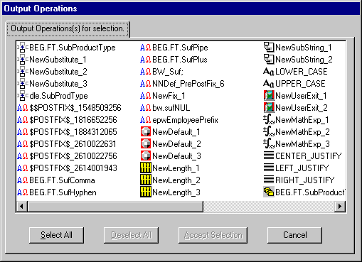
Notes: To reorder component output operations or output operation collections, click and drag the component to the highest level of the collection.
To move one operation to a partition preceding another operation, drag the operation that you want to move and place it on top of the operation that it should precede. You can rearrange the other components to fit the new order using this method.
Output Operations
Output operations provide the different actions that can be performed on an output field. Using operations, you can, for example, change the case of output data, perform mathematical expressions based on input field contents, and extract substrings.
Through the use of output operation collections, you can collect operations to perform them sequentially. For example, you can left justify and right trim a substring of the contents of an input field. The order in which these operations are defined in the collection is the order in which they are performed.
Available operations are described in Table 3-4.
|
Output Operation Type |
Description |
|---|---|
|
Case |
Case operations affect the case of the field data. The two defined case operations are LOWER_CASE and UPPER_CASE. |
|
Default |
Default operations provide a default value for a field if an input field either does not exist in the input message or has a length of zero. |
|
Prefix/Suffix |
Prefix/Suffix operations enable you to attach literals to the beginning or end of the field data. Note: The NULL value option forces the prefix/suffix value to be generated. |
|
Justification |
Justification operations justify field data to be left, center, or right within the length of the field. For pad characters, Justify operations must proceed a Length operation in a collection. To specify a pad character other than the default (a space), select the desired pad character in the associated Length operation. If Center Justify is specified, the data can be padded on both the left and right. The Justify and Length operations are related. |
|
Length |
Length operations ensure that an output string is given a length. If the data length is longer than the specified length, the data is truncated. If the data length is shorter than the specified length, pad characters are used. Non-numeric data types are padded on the right; numeric data types are padded on the left. The Length and Justify operations are related. |
|
Math Expression |
Math Expression operations output a value resulting from an arithmetic expression. The expression can be built using arithmetic operators, constants, and input field values. For more information, see Math Expression. |
|
Substitute |
Substitute operations enable you to define a list of input strings to substitute and the output strings to replace them. For each substitute item within a substitute operation, define a literal to look for as the input value, a literal to replace it with, and the data type in which to output the new data. For more information, see Substitute. |
|
Substring |
Substring operations enable you to extract a portion of an input string, defined by start byte position and length, and place it in the output field. |
|
Trim |
Trim operations remove a defined trim character to the right and left of the output data. |
You can define a default operation using the steps described in the following procedure.
The cursor is positioned in the text box where you can type a unique operation name.
Note: Default operation names have a 32-character maximum length.
Prefix/Suffix
Prefix/Suffix operations allow you to specify a literal for use as a prefix or suffix. Prefixes are added to the beginning of an output field. Suffixes are added to the end of an output field. For example, you may want to place a less-than sign (<) before and a greater-than sign (>) after the output data. This would require a Prefix of < and a Suffix of >. Any defined literal may be used as a prefix or suffix.
You can define a prefix/suffix operation using the steps described in the following procedure.
The cursor is positioned in the text box where you can type a unique Prefix/Suffix operation name.
Note: Prefix/Suffix Operation names have a 32-character maximum length.
Length
You can define a Length operation by using the steps described in the following procedure.
The cursor is positioned in the text box where you can type the new, unique Length operation name.
Note: Length Operation names have a 32-character maximum length.
Math Expression
Using math expression operations, you can output a value resulting from an arithmetic expression. The expression can be built using arithmetic operators, constants, and input field values.
When input field names are used in math expressions, the math expression parser extracts the current value for the fields specified in the math expression. Alternatively, you can define a single math expression to use input fields that are currently mapped to the output for which the output math expression is applied. The string $MAPPED_INFIELD in a math expression is used in place of or in addition to field names. The value of the input field that is currently mapped to the output field replaces $MAPPED_INFIELD.
For example, suppose the following relationships exist.
If you apply the math expression inField1 + $MAPPED_INFIELD to OutField2, the result is 210. Likewise, if you apply the same math expression to OutField3, the result is 310.
The ability to substitute the value of the currently mapped input field is useful when the same calculation is applied to multiple input fields. Instead of defining a unique math expression with the same calculation for each field and explicitly naming fields in each math expression, define a single math expression containing $MAPPED_INFIELD. Use this math expression in all of the output controls associated with the output fields that are mapped to the input fields modifying the calculation.
Note: The math expression function ignores results and data from any previous operations.
For example, suppose you define an input message with fields InF1, InF2, and InF3, and an output message is defined with field OutF1. You could define a math expression as part of an output control associated with output message field
OutF1 as: InF1 + InF2 * -InF3
This expression is evaluated as InF1 + (InF2 *(- InF3)) based on the precedence rules.
Other expression examples include:
InF1 + -InF2
InF1 * 8
InF1 * 9.3
InF1 * -8
InF1 * -9.3
(InF1 + InF2) * 3/InF3
(InF1 * (InF2 + InF3) * 4)
You can define a math expression operation using the steps described in the following procedure.
The cursor is positioned in the text box where you can type a unique math expression operation name.
Figure 3-9 Math Expression Properties Tab
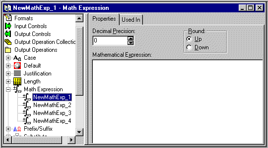
Note: When multiplying fields in math expressions, multiply by 1.0 to avoid erroneous characters after the decimal. To set up an output control to handle a 6-digit ASCII number and insert a decimal, multiply the number by 1.000 where the number of zeroes after the decimal equals the amount of decimal precision required in the final number. Do not use terminating characters such as carriage returns or line feeds.
Substitute
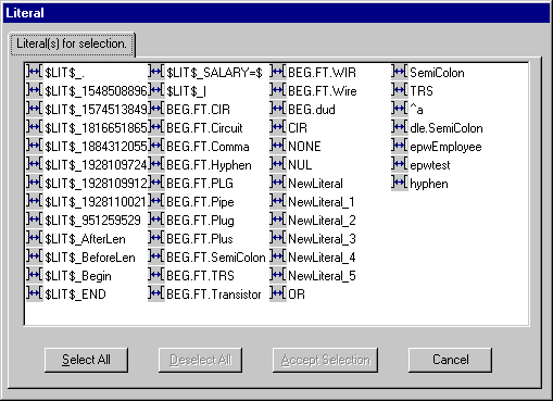
Substitute operations enable you to define a list of input strings to substitute and the output strings to replace them.
For example, each time Formatter receives the value x as input, you want to output the value as xx. You can change the value from the input of x to the output of xx.
You can add a literal with the value NONE and assign it an output value. This acts as a default substitution if there is no match for the input value.
You can define a Substitute operation using the steps described in the following procedure.
The cursor is positioned in the text box, where you can type a unique Substitute operation name.
Note: Substitute operation names have a 32-character maximum length.
The Substitute operation itself has no properties. You must add Substitute Items.
Figure 3-10 Literal
Substring
Substring operations extract part of an input field's contents (defined by byte position and length) and places it in the output field. Only the String, Numeric, EBCDIC, and Binary data types can be used for substrings.
You can define a substring operation using the steps described in the following procedure.
The cursor is positioned in the text box where you can type the new, unique substring name.
Note: Substring operation names have a 32-character maximum length.
Trim
You can define a Trim operation using the steps described in the following procedure.
The cursor is positioned in the text box where you can type a unique Trim operation name.
Note: Trim Operation names have a 32-character maximum length.
Formats
Use the Formats function to build both input and output formats. The formats can be either flat or compound.
The component formats of a compound format are either optional or mandatory. An optional component can have missing components, and the parse or reformat will still succeed. A mandatory component must exist, and all its mandatory components must also exist, or the parse or reformat will fail. The component formats are mandatory by default.
Before creating flat or compound formats, define their component parts. The component parts for each format are described in Table 3-5.
|
Format |
Components |
|---|---|
|
Flat input format |
Literals, fields, and input (parse) controls |
|
Flat output format |
Literals, fields, and output controls, output operations, and output operation collections |
|
Compound input format |
Flat input formats or other compound input formats |
|
Compound output format |
Flat output formats or other compound output formats |
You can create a new format using the steps described in the following procedure.
|
Format Termination Value |
Description |
|---|---|
|
Not Applicable |
No data termination. Read to end of message. |
|
Delimiter |
The format is terminated by a delimiter. |
|
Exact Length |
The format has a fixed length. |
|
White Space Delimited |
The format is terminated by a white space. |
|
Minimum Length + Delimiter |
Parse a minimum number of characters and then look for a delimiter. |
|
Minimum Length + White Space |
Parse a minimum number of characters and then look for a white space. |
If the termination type is Delimiter or Minimum Length + Delimiter, select a literal from the Delimiter drop-down list.
If the termination type is Exact Length, Minimum Length + Delimiter, or Minimum Length + White Space, enter the fixed length of the field or the minimum number of characters to parse before looking for a delimiter or white space in the Length field.
Notes: When selecting components for the format, make sure each component has associated input controls and fields on its property sheets.
To select fields used in another format, click the Format Filter drop-down list and select a format. The field list changes to list only fields that appear in the selected format. To return to the complete list of fields, click the Format Filter drop-down list and select Not Applicable.
Saving a Flat Input Format as a Flat Output Format
The flat output format mirrors, as much as possible, the contents of the flat input format; however, the termination type, length, and delimiter are defaulted for the output flat format.
You can save a flat input format as a flat output format using the steps described in the following procedure.
For example, the first time the flat input format is saved as a flat output format, it is saved as OFF_NewInputFormat_1. The second time, it is saved as OFF_NewInputFormat_2.
The Objects Created Summary dialog appears containing a list with the new format name and any controls created.
Alternative Input and Output Formats
Alternative formats are a special form of compound format in which one format in a set of alternatives will apply to a message. For example, if an alternative format is named A, it may contain component formats B, C, and D. A message of format A may actually be of variation B, C, or D.
Exactly one of the alternatives must apply or the entire alternative compound format does not apply.
An alternative format can be used anywhere a format can be used, and each component format can be any kind of its respective parent input or output format.
Optional Components and Fields
Optional components and fields are each characterized as optional within the context of a compound object.
For example, a compound format composed of component formats may have a mix of mandatory and optional component formats. A format may also have a mix of mandatory and optional fields.
If a mandatory component (of a format or field) is not present in a message, the compound or flat format does not apply. However, if an optional component is not present, Formatter continues to the next component. All component formats in an Alternative Compound should be mandatory.
Alternative Input Formats
If an alternative input format is applied to an input message, the first component of the alternative format is compared to the message. If it parses with the first component format, parsing is finished. If parsing fails, Formatter tries the second component format. If that fails, it tries the next component format. If all components fail to parse, then the parse for the entire alternative input format fails.
Alternative Input Formats and Parsing
If a format has optional fields and the fields are delimited and not tagged, it may be impossible to determine which of the optional fields occur in an input message. For example, if a simple space-delimited format is:
[F1] F2 [F3] [F4]
The first, third, and fourth fields are optional. If an input message value1 value2 value3 is received, there is no way, without some rules to remove ambiguity, to determine if the message is actually F1 F2 F3, F2 F3 F4, or F1 F2 F4.
Alternative input formats enable you to specify all possible configurations of mandatory and optional fields in a format. You must explicitly define all possible combinations to avoid possible parsing errors-Formatter does not recursively try all combinations.
As an example, if you have the following input format:
Field 1: optional, comma delimited
Field 2: mandatory, colon delimited
Field 3: optional, comma delimited
Field 4: optional, forward-slash delimited
The input message "field1,field2:field3,field4/" parses into four fields correctly. However, "field1 field2:field3,field4/" fails. The first field of the format is comma delimited and parsed as "field1 field2:field3". The second field is colon delimited, so Formatter looks for a colon in "field4/", detects the end of the message, and fails to parse.
You have to explicitly define all possible combinations (F1 F2 F3, F2 F3 F4, F1 F2 F4). In this case, the second alternative format would have three fields, starting with the mandatory colon-delimited field.
For alternative formats, you determine the order in which alternative components are parsed. Remember that components are taken on a first-parsed, only-parsed basis. With that in mind, component order is critical.
For example, if you have a message "abcde," you could specify two alternatives (or more). It could be parsed into a 5-byte field or two separate fields, one 2-bytes long and one 3-bytes long. If the 5-byte field format is the first alternative, you will never parse using the second format. If two parses are valid for the same input, only the first occurs.
Alternative Output Formats
To format an alternative output format, Formatter attempts to create the first component of the alternative format. If creating the first component is successful, formatting is finished. If it fails, Formatter tries to create the second component, and so on. If all components fail to be created, formatting the alternative output format fails.
For information on using alternative formats in Formatter, refer to Output Controls.
Note: A component is not created if a mandatory component or field for the output format is not present in the incoming message.
Tagged Input Formats
A compound format can have a property of Tagged Ordinal. This means that the first field in each component format is a literal. The component format can be flat or compound.
Tagged Input with Alternative Component Example
Tagged input formats can be useful when used in conjunction with alternative formats. The following is an example of what might come in the data segment of a SWIFT message.
":10:f1 f2 f3<CRLF>:20:C/1234/<CRLF>first description<CRLF>second description<CRLF>:30:f4,f5<CRLF>"
The following is a loose definition of the format:
:10: field1 field2 field3 <CRLF>
:20: [C/acctnum/< CRLF>] (optional)
desc1 <CRLF>
[desc2 <CRLF>] (optional)
:30:first, second <CRLF>
Parse segment :20: using the following rules:
With tagged formats, you now have a way to ensure that you do not overrun the boundaries of the :20: segment. Any trailing optional fields in a tagged flat format can be parsed or determined to be absent by parsing only up to the component boundary, instead of looking for a field delimiter (or other termination) beyond the component boundary.
Define a compound tagged format with three components as follows:
Segment10 :
	First Field Literal ":10:"
	space-delim field
	space-delim field
	<CRLF> delim field
Segment20 : Alternative format with two components
Segment20_1 (this is the first alternative component)
	First Field Literal ":20:"
	Credit Code : slash delim, mandatory
	AcctNum :  /<CRLF> delim, mandatory
	desc1 : <CRLF> delim, mandatory
	desc2 : <CRLF> delim, optional
   Segment20_2 (this is the second alternative component)
	First Field Literal ":20:"
	desc1 : <CRLF> delim, mandatory
	desc2 : <CRLF> delim, optional
Segment30 :
   First Field Literal ":30:"
   comma delim field
   <CRLF> delim field
When parsing a Segment20, the parser first attempts to parse Segment20_1. If it fails, it parses the second alternative. The credit code and account number are not part of this particular :20: segment.
You could have different first field literals for 20_1 and 20_2 (for example, :20A: and :20B:) like SWIFT sometimes does.
You can include tagged input format as a component of a compound, where the other components can be any other kind of input format. For SWIFT, you might define a SWIFT 570 message as a compound ordinal of three components:
	Basic Header : Ordinal Flat Format
	570 Data Segment : Tagged Compound Format
	Trailer : Random Tagged Flat
Tagged formats do not apply to output formats. An output format can certainly have a first field literal, but calling it a tagged format does not gain anything. It is only when you need an additional way to determine message boundaries when parsing an input message where first field literals become necessary.
Alternative Output Format Example
Creating an output format is conceptually clearer. You define a set of alternatives, then define an alternative compound having all of the alternatives as components, sequenced in order of desirability. As with input formats, it may be appropriate to order alternatives from specific to general. (This is not always the case. Many times, order is irrelevant on output because of mutually exclusive mandatory fields; there is only one format that applies.)
Using the previous description of a :20: segment, assume you have to create a :20: segment instead of parsing it. You do not know what kind of input message you had, whether it was a Segment20_1, Segment20_2, or some other input format that allowed a parse of some or all of the fields required for a segment 20.
You cannot just say you have some optional leading fields CreditCode and AcctNum, because you have to put in a <CRLF> if the fields exist, but not if they do not.
Create a set of two alternatives:
Seg20_1 1literal :20:
	2CreditCode Mandatory with / delim
	3AcctNum Mandatory with /<CRLF> delim
	4desc1 Mandatory with <CRLF> delim
	5desc2 Optional with <CRLF> delim
Seg20_2 1literal :20:
	2desc1 Mandatory with <CRLF> delim
	3desc2 Optional with <CRLF> delim
Notice the similarity between the two. It is easy to go from most specific to more general by using the Formatter Save As and Field Delete features. By having several mandatory fields in a format, you are ANDing their existence together. All must be present to create the given format. If you sequenced Seg20_2 before Seg20_1 in the alternative output (compound) format, Seg20_1 would never be applied.

|

|

|
|
|
|
Copyright © 2000 BEA Systems, Inc. All rights reserved.
|