As shown in Figure 2-2, the main window provides two types of views:
In general, you select resources on the right panel and then configure your application based on those resources by populating the Current Application tree with them.
Note:
You cannot add a machine from the Configuration Expert main window. To add a new machine, you must use the Configuration Data Editor. For more information see the task Using the Configuration Data Editor.
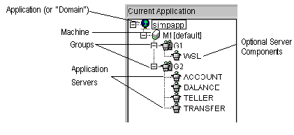
The hierarchical tree showing in the left panel represents the BEA TUXEDO configuration for the current application. You add components to the configuration tree by selecting items in the right panel and clicking on the Add button. When a resource is in use in a configuration it is displayed in the tree. (A resource in use will also still show in the right panel as an available resource.)
You can define or modify the properties for a resource at any time from either the configuration tree (left panel) or from the available resources on the right panel. For more information, see in this manual.
Figure 2-3 shows how components look when they are added to a configuration.
Table 2-1 explains the components represented in the configuration tree view.
Configuration for the Current Application
(left panel tree)Figure 2-3 Configuration Tree

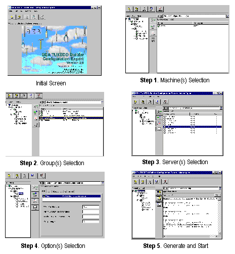
The right panel displays a sequence of steps for you to define the available resources and build your configuration. There are a total of five steps as shown in Figure 2-4.
We recommend that you configure at least your first few applications by using the tasks in the following suggested sequence.
This step allows you to define the properties for machine(s), add machine(s) to the configuration tree (Add button), delete any machines not required in the configuration tree (Delete button), or modify those currently in the tree (Modify button).
Note:
You cannot add machines from this window. If you need to add a machine, use the Configuration Expert Editor as described in Using the Configuration Data Editor.
When you have adequately defined machine(s) and added those needed to the configuration tree, click on the right arrow at the top of the panel to continue.
This step allows you to add group(s) to the configuration tree (Add button), delete groups not needed in the configuration (Delete button), or modify those currently in the tree (Modify button).
Note:
Groups can only be added if a machine or a lower level node (group, server) is selected in the tree view. You can change group names in the Group Properties window (Props button).
When you have adequately defined group(s) and added those needed to the configuration tree, press the right arrow at the top of the panel to continue.
This step allows you to deploy servers to the proper server groups. The initial list of servers comes from the generated servers file( It is also possible to create servers that are exposed to the The list of available servers matches the corresponding Resource Manager type; for example, None, Oracle_XA, and so on. For more information on the Resource Manager file, see Resource Manager Template File.
This step allows you to configure optional components, specifically /WS, Jolt, Repository, Queue, or Event elements to the configuration.
This step allows you to generate a configuration file. It also allows you to start your application from the Configuration Expert when the Configuration Expert is running on the master machine of the application.
Note:
The start and stop capabilities in this step are only available if the local machine is the master machine.
Figure 2-4 shows the suggested task sequence for using the Configuration Expert. As shown, you can step backwards and forward through the steps as needed. You can also go immediately to any step screen by choosing Go-><Name of Step> from the menu bar.
Steps to Follow (right panel)
Step 1: Configure Machine(s)
Step 2: Configure Group(s)
Step 3: Configure Server(s)
gservers.lst) and the available server file(iservers.lst). It is possible to add servers to a server group when a group or a lower-level node (server) is selected in the configuration tree view.
iservers.lst file.
Step 4: Configure Optional Component(s)
Step 5: Generate and Startup
Suggested Task Sequence
Figure 2-4 Task Sequence (suggested by right and left arrows)
