

|
The following sections describe how to configure WebLogic SIP Server domains to support the SIP traffic and features required in your organization:
BEA WebLogic SIP Server runs on a wide variety of hardware, and provides a highly scalable architecture that can be deployed on multiple machines. Capacity planning is the process of determining the hardware configuration that is required to meet your organization's performance and reliability goals. This document provides capacity planning suggestions for WebLogic SIP Server with a focus on server hardware requirements.
| Notes: | Capacity planning is not an exact science. Every application is different, particularly converged HTTP and SIP applications. This document is intended as a general guide for planning server deployments; it uses conservative estimates for basic hardware components and deployed applications. You should err on the side of caution when planning for applications or hardware that differ from the basic recommendations described in this document. |
| Note: | Any and all recommendations generated by this guide should be verified by actual benchmarks before placing a system into production. |
| Note: | Your BEA sales or professional services representative may have more detailed capacity planning information than is available in this document. |
WebLogic SIP Server is implemented using a flexible architecture in which you can easily add servers as needed to increase throughput for SIP traffic, or to provide high reliability for defending against hardware failures. The primary goal of capacity planning for WebLogic SIP server is to determine the size and configuration of the WebLogic SIP Server engine tier, which hosts application logic, and the data tier, which stores the call state for SIP messages. Both tiers may be extended to improve throughput or to increase the availability of services on your network.
See Overview of the WebLogic SIP Server Architecture for more information about the basic architecture of a WebLogic SIP Server deployment.
Accurate capacity planning begins with a clear understanding of the throughput and reliability requirements for your deployed applications. The following questions will help drive the capacity planning process for WebLogic SIP Server:
If you deploy a B2BUA that generates more SIP messages for each call, each WebLogic SIP Server instance will support fewer calls per second. If you deploy an application that generates fewer SIP messages per call, or if your system provides mainly proxy services, then each server can support additional call volume.
| Note: | The deployment scenarios described in this document use estimates for call duration, call state size, and number of SIP messages per call for a B2BUA application. BEA has derived these estimates from working with organizations that are deploying WebLogic SIP Server for production use. The derived numbers are generally conservative and provide workable hardware estimates for many production environments. However, if your system or application differs significantly from the estimated numbers, you must perform additional profiling to determine the exact hardware configuration required. |
| Note: | WebLogic SIP Server start scripts use default values for many JVM parameters that affect performance. For example, JVM garbage collection and heap size parameters may be omitted, or may use values that are acceptable only for evaluation or development purposes. In a production system, you must rigorously profile your applications with different heap size and garbage collection settings in order to realize adequate performance. See Tuning JVM Garbage Collection for Production Deployments for suggestions about maximizing JVM performance in a production domain. |
The capacity planning scenarios described in this document use one or more basic machine configurations consisting of:
Each machine should host either a single WebLogic SIP Server engine tier server instance (which uses both processors) or two WebLogic SIP Server data tier server instances (with one processor per instance).
Because the engine tier relies on data tier servers in order to retrieve call state data, BEA recommends using dual Network Interface Cards (NICs) on engine and data tier machines to provide redundant network connections. Gigabit Ethernet is required for the high throughput achieved in most production deployments. See Throughput Values for WebLogic SIP Server Instances for more detailed throughput calculations.
The JVM for each engine tier server should use the minimum amount of heap space required for your deployed applications. This document assumes roughly 700 megabytes per engine tier server instance. Data tier servers should use the maximum possible heap space for the Java Virtual Machine. This document use a conservative value of 1.6 gigabytes per JVM.
If your organization uses substantially different machine specifications, you will need to profile the hardware to determine the exact throughput capabilities for each machine.
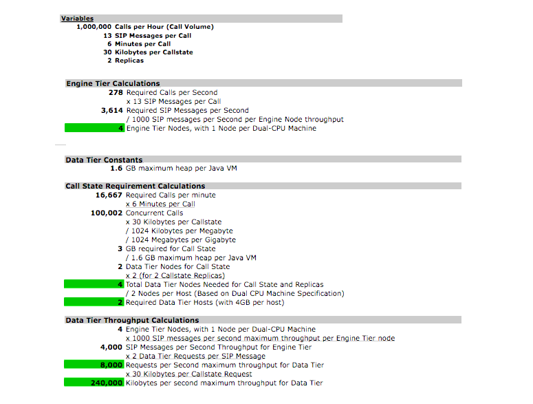
With the processing power provided by the basic hardware configuration described above, each WebLogic SIP Server instance in the engine tier cluster can process and originate approximately 1,000 SIP messages per second, or 76 calls per second per second (assuming 13 SIP messages per call for a single B2BUA Servlet as shown in Figure 6-1). This basic throughput value is used to drive the hardware requirements for the WebLogic SIP Server engine tier.
The size of the WebLogic SIP Server data tier is driven by the expected total number of simultaneous calls managed by the deployment. Given the total number of concurrent calls and the average size of the call state, you can determine the maximum amount of RAM required to store concurrent calls state for your system. This value is multiplied according to the number of redundant call state replicas you wish to deploy for high availability. The total RAM requirement is then divided by the maximum heap size per JVM to determine the number of data tier nodes, and ultimately the number of host machines required in the WebLogic SIP Server data tier.
Figure 6-2, Using Throughput Values to Determine Engine and Data Tier Requirements, on page 6-6 shows the sample calculations used to determine the medium-sized deployment described in Medium Deployment.

Given the basic hardware configuration and expected throughput values described in Sample Deployment Scenarios, you can quickly estimate the total number of clustered WebLogic SIP Server instances that are required in the engine and data tiers, as well as the total number of hosts and RAM required in each tier. The following sections describe common deployment sizes used in production environments:
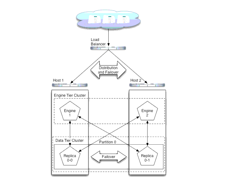
A typical small deployment of WebLogic SIP Server consists of two dual-CPU machines each running two WebLogic SIP Server instances. A system of this size can process over 500,000 calls per hour, given the hardware and throughput values described in Basic Hardware Configuration and Throughput Values. The small deployment utilizes only a single partition in the data tier, but with two replicas to provide failover if one of the engines should fail. A load balancer distributes client connections and performs failover from one engine tier server to the other if an engine tier node fails or is brought down for maintenance. This configuration is shown in Figure 6-3.
| Note: | The exact configuration shown in Figure 6-3 should only be used in cases where limited hardware is available. Although limited failover is provided via two replicas in the data tier, the overall throughput of the system is greatly reduced should one of the machines fail. |

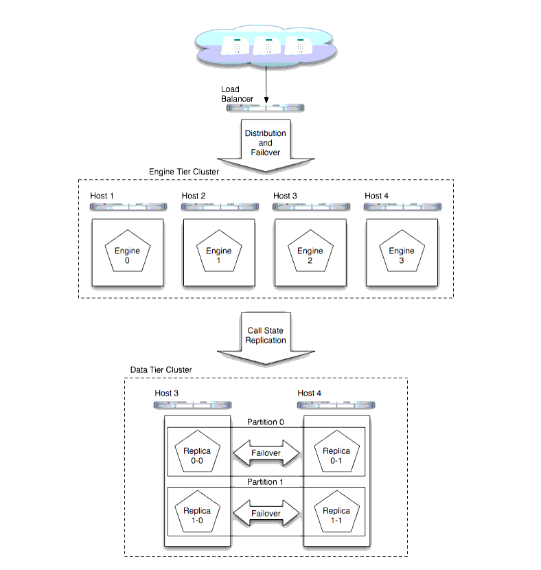
A typical medium deployment, shown in Figure 6-4, is configured to support a call rate of one million calls per hour. In the engine tier, four WebLogic SIP Server instances (deployed on four Dual-CPU machines) are required to support the call throughput. In the data tier, two partitions are required to manage the call state for the maximum number of expected concurrent calls. Two replicas in each partition provide replication and failover in the event of a data tier host failure.

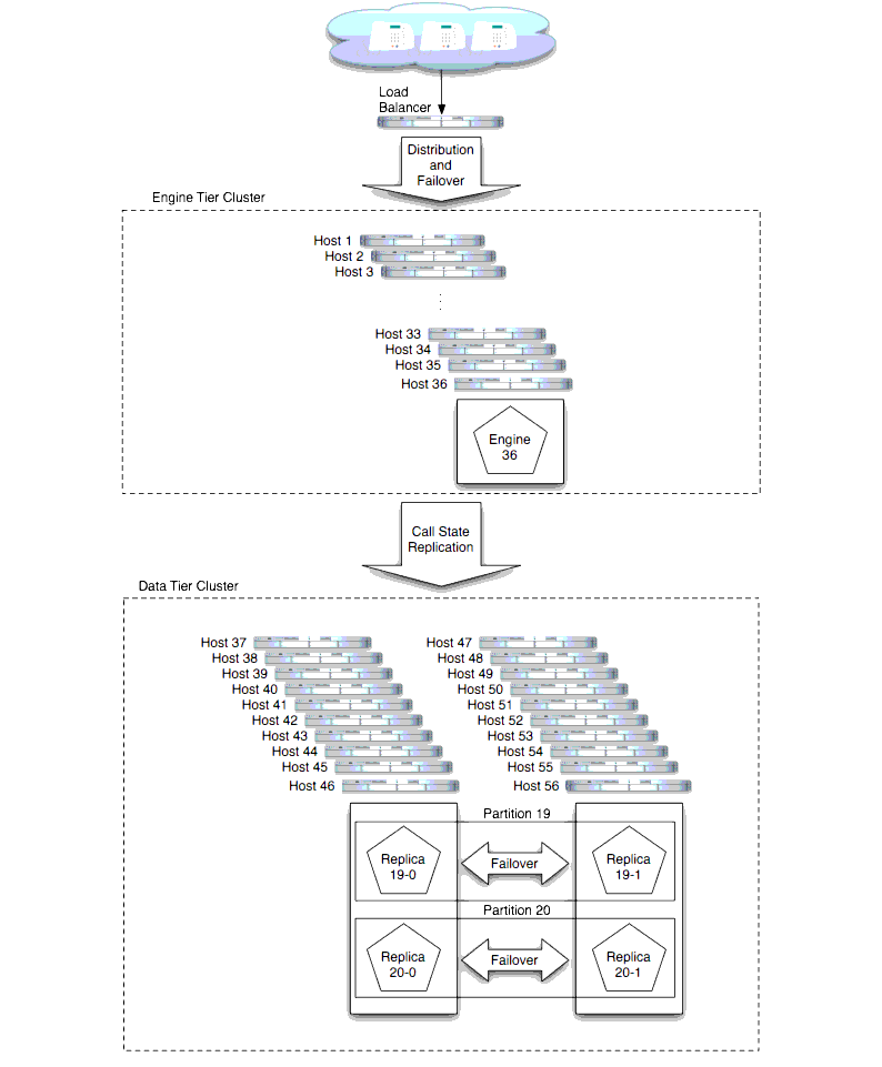
In the sample large-scale deployment, both the engine tier and data tier clusters have been expanded to support a call rate of 10 million calls per hour, as shown in Figure 6-5, Large-Scale Deployment, on page 6-11.
In the engine tier, 36 nodes are required given the maximum throughput per node value of 1,000 SIP messages per second.
In the data tier, 20 servers are required to manage the call state for the estimated number of concurrent calls. However, to provide redundancy in the event of a failure, two replicas in each partition store copies of the partition's call state, resulting in 40 server nodes in the data tier.
To maximize the reliability for such a large deployment, each group of servers in the data tier should be located in different physical locations, and/or on separate, dedicated networks.


|