|
|
This step describes how you design a common pattern in business processes—one that selects one path of execution based on the evaluation of one or more conditions. You create this pattern by designing a Decision node in your business process.
In this part of the tutorial scenario, the business process is designed to make a decision based on a value that the business process extracts from the variable to which the XML message from the client is assigned. You design a single condition, which is evaluated at run time to determine whether the shipping address, specified in the incoming Request for Quote xml, requires that sales tax is calculated for the quote. If the condition evaluates to true, then sales tax must be calculated and the flow of execution proceeds along a branch that calls a Web service to calculate the sales tax. If the condition evaluates to false, then no sales tax is required for the quote and the flow of execution proceeds along the default branch. This step includes the following tasks:
 Show ViewNode Palettefrom the BEA Workshop menu. From the Select Perspective dialog box, select Process. The Node Palette is now visible.
 Decision in the Node Palette, then drag and drop the Decision node onto the business process, positioning it directly below the Client Requests Quote node that you created in Step 2: Specify How the Process is Started.
| Note: | As you drag a node from the Node Palette onto the Design view, targets  appear on your business process. As you drag the node near a target location, the target is activated appear on your business process. As you drag the node near a target location, the target is activated  and the cursor changes to an arrow and the cursor changes to an arrow  . When this happens, you can release the mouse button and the node snaps to the business process at the location indicated by the active target. . When this happens, you can release the mouse button and the node snaps to the business process at the location indicated by the active target. |
The Decision node includes a node representing the condition (labeled Condition) and two paths of execution: one for events to be executed in the case the condition evaluates to true and the other (the Default path) for events to be executed in the case the condition evaluates to false.
| Note: | If the Name box is not open, double-click Decision to open it. |
The Decision node in your business process should now appear in the Design view as shown in the following figure.
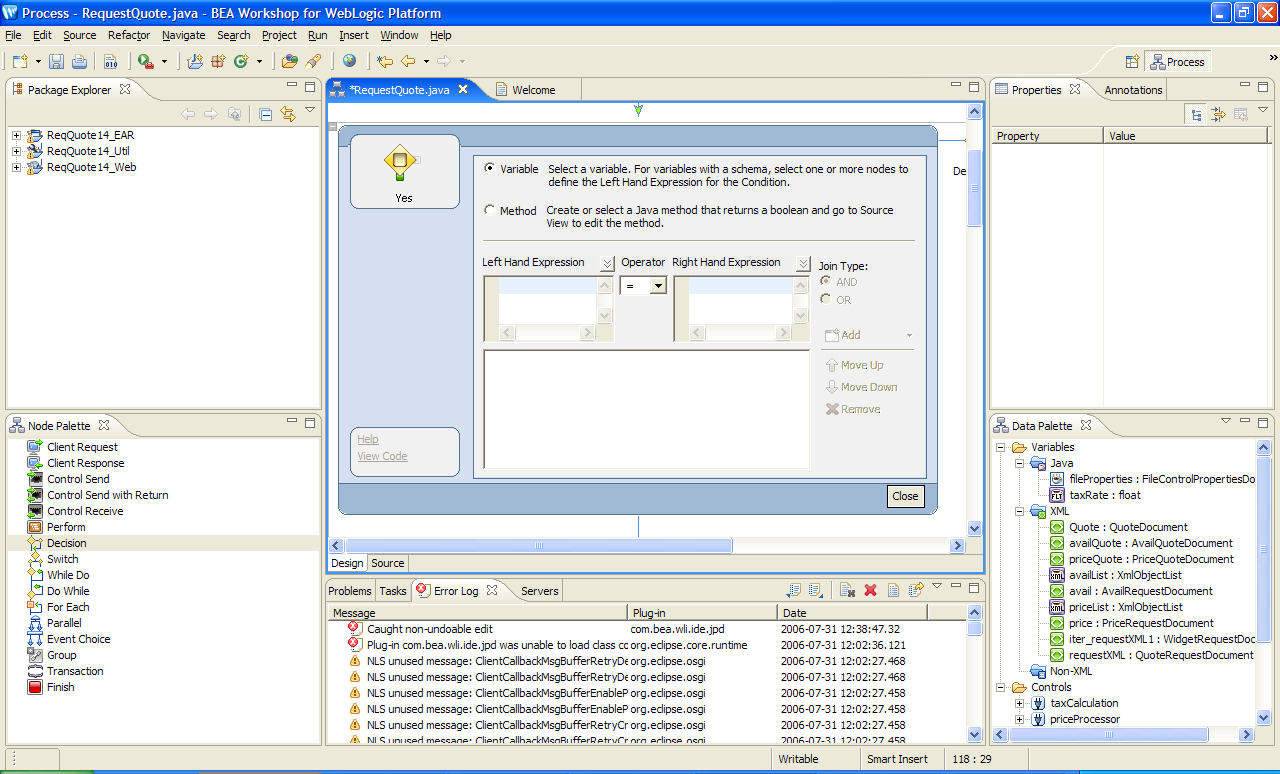
 to invoke the decision builder. It provides a task-driven user interface that helps you design the decision logic.
In the decision builder, Variable is selected by default. Do not change the selection because, in this case, you design the decision based on the value of an element in an XML document, which is valid against an XML Schema.
 for the Left Hand Expression.
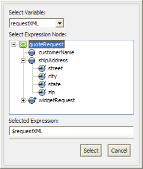
A drop-down list of variables in your project is displayed. In this case, the variable you created for the Client Request node at the start of your business process is displayed: requestXML.
A representation of the XML schema for the QuoteRequest is displayed in the Select Expression Node pane:
The elements and attributes of an XML document assigned to this variable are represented as nodes in a hierarchical representation, as shown in the preceding figure. The schema in our example (QuoteRequest.xsd) specifies a root element (quoteRequest), and child elements: customerName, shipAddress, and a repeating element (identified by  ):
): widgetRequest. The shipAddress element contains the following attributes: street, city, state, zip.
This selects the node in the XML document that represents the element for which you want to define the condition.
The Selected Expression field is populated with the following expression:
fn:data($requestXML/ns0:shipAddress/@state)
The Left Hand Expression field is populated with expression.
"CA" in the Right Hand Expression field. fn:data($requestXML/ns0:shipAddress/@state) = "CA"This completes the design of the first condition on this node.
"CA", then change the entry to "California".The conditions you specify are listed in the condition list pane, as shown in the following figure.
The icon for the Condition node in the Design view has changed from to  . It is a visual reminder that the condition you defined on this node is based on the evaluation of XML.
This step completes the design of the condition that is evaluated when the flow transitions to the Decision node at run time. Your condition logic is written in source code as an XQuery expression—see the following section: XML Conditions in the Source Code.
You are ready to define the actions on the subsequent paths in the flow—proceed to
Step 4: Invoke a Web Service.
As you define your XML conditions in the decision builder, BEA Workshop writes an XQuery expression to the JPD file. Specifically, XQuery expressions are written in the Process Language region of the JPD file.
To view the XQuery expression written in keeping with your work in the preceding section, click the Source tab.
The condition defined by following the example in steps 2 through 9 in the preceding section creates the following XQuery expression in the source code:
@com.bea.wli.common.XQuery(prolog=
	"declare namespace ns0=\"http://www.example.org/request\";" +
"declare function cond_requestXML_1($requestXML as element()) as xs:boolean {" + " (((data($requestXML/ns0:shipAddress/@state) = \"CA\") or (data($requestXML/ns0:shipAddress/@state) = \"California\")) or (data($requestXML/ns0:shipAddress/@state) = \"NJ\")) or (data($requestXML/ns0:shipAddress/@state) = \"New Jersey\")" + "};" + "declare function get_requestXML1($requestXML as element()) as element()* { " +"$requestXML/ns0:widgetRequest" +
"};",
Defining Conditions for Branching


|