


|

|
|
|
|
Defining Actions
The following sections introduce and explain how to use WebLogic Integration actions to accomplish various workflow activities:
Understanding Actions
While nodes and connections serve to specify the logical sequence and control of business processes, it is actions that perform the real work of a workflow definition. An action is the most basic unit of a workflow that can perform some activity. This activity may be as simple as initializing a variable, or as complex as calling a custom application on a client system. Actions can be added to all types of nodes (except Joins), to exception handlers, and even to other actions.
The following sections provide important background information for using actions to perform activities in workflows. It includes:
Action Categories
Actions are organized into categories in the Studio. In this guide, however, we categorize actions into the major activities that you can perform. The following table lists the categories, the actions contained within them, the activities they accomplish, and the sections of the guide where each one is described in more detail.
Understanding Action Types and Placement
In addition to the action categories presented by the Studio, such as Task, Workflow, Integration, Exception Handling, and Miscellaneous categories, you should be aware of other distinctions between actions and their behavior:
These distinctions are significant, as they can affect the order in which workflow operations are executed. Each of these distinctions is described in more detail in the following sections.
Terminal Actions and Non-Terminal Actions
Most actions are terminal, meaning that they cannot contain any other actions. However, some actions allow you to define sub-actions inside of them that are performed according to specific conditions, depending on the nature of the parent action. The following actions can have sub-actions defined within them and are, therefore, non-terminal:
Note that sub-actions are only visible in the Properties dialog box for these non-terminal actions, but do not appear in the folder tree.
The special relevance of non-terminal actions is that, while most terminal actions are always executed in a synchronous fashion, which means that the workflow waits until they have finished executing, non-terminal actions can perform operations that are executed in both a synchronous or asynchronous fashion. Asynchronous execution of non-terminal actions means that the workflow does not wait for the action's operations, or its sub-actions, to complete before proceeding, but continues to be processed in parallel. This distinction is explained in more detail in the next section.
Synchronous and Asynchronous Execution of Actions
All actions are synchronous, which means that the workflow does not proceed to the next action until the operations performed by the current action have completed, with the exception of the following:
However, the following actions, and any sub-actions they may contain, can be executed in a synchronous or asynchronous fashion, depending on how you place the action:
These non-terminal actions and their sub-actions are performed asynchronously in the following conditions:
Figure 6-1 Non-Terminal Action in Task Node with Task Marked Done from Task Properties
In these cases, the action's operations, and any specified sub-actions, are simply performed in parallel with the subsequent nodes in the workflow, as illustrated in the following figure.
Figure 6-2 Asynchronous Execution of Workflow Actions
By contrast, non-terminal actions and their sub-actions are performed synchronously if the Task node in which they are placed is marked done in the action's properties, as illustrated in the following figure. Figure 6-3 Non-Terminal Action with Task Marked Done in Action Properties
That is, the workflow waits until all operations and sub-actions are completed before proceeding to the next node, as illustrated in the following figure. Figure 6-4 Synchronous Execution of Workflow Actions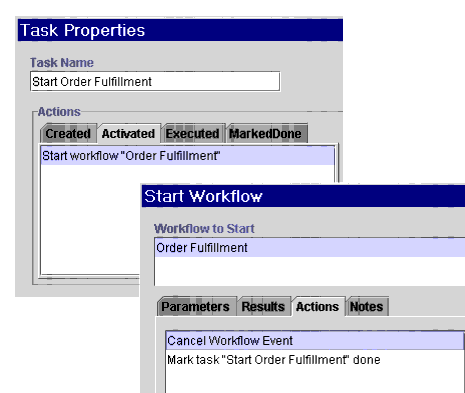
More information on action design issues is provided in the following topics: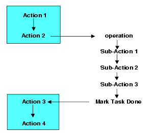
More information on marking tasks done is provided in the following sections.
Placing Actions in Task Nodes
When you use Task nodes, you need to know how to place actions in order to perform a particular activity. This requires that you do the following: place the action on the correct tab of the Task Properties dialog box (Activated or Executed), and mark the task done at the appropriate point. For more information on Task Properties dialog box tabs, see Understanding Task States.
Using the Activated and Executed Tabs
The only ways a task can be executed are:
Thus, in general, you can follow these guidelines when considering action placement:
A detailed table with guidelines for using Task Properties dialog box tabs to perform each of the major activities identified in this guide is provided in Guidelines for Action Placement in Task Nodes.
Marking Tasks Done
All tasks must be marked done, either manually by a Worklist or custom client user, if the Mark Done Without Executing permission is assigned to the task (for more information, see About Task Permissions), or explicitly at design time by using the Mark Task as Done action.
If a task is not marked done, the workflow will not proceed from the Task node. Conversely, any actions that are listed after a Mark Task as Done action in the Task Properties dialog box are not performed, unless they are placed on the Marked Done tab of the Task Properties dialog box.
Note: In a similar fashion, any actions placed after the Mark Task as Done action in the action properties dialog box for a non-terminal action (as described in Synchronous and Asynchronous Execution of Actions) are not performed.
These are general guidelines you can use for marking tasks done:
Figure 6-5 Marking Non-Executed Tasks Done
Figure 6-6 Marking Executed Tasks Done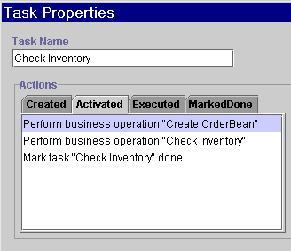
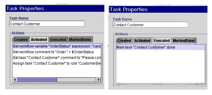
A detailed table with guidelines for using Task Properties dialog box tabs to perform each of the major activities identified in this guide is provided in the following section.
Guidelines for Action Placement in Task Nodes
In general, you should try to place actions in Task nodes only, and avoid using them in other types of nodes. You should also use shorter action lists in more Task nodes, rather than longer action lists in fewer Task nodes. Using a "shallow" or "flat" design approach ensures that the logic and transactional units of your workflows remain immediately apparent in their graphical representations.
In some cases, however, it will be necessary to specify more than one action in the same node, for example, when you need to specify various properties of a user-assigned task. (For more information, see Setting Up Manual Tasks.) Similarly, you may find it more efficient in some cases to simply add an action to nodes other than Tasks, or even to the action list in a Task node, rather than to complicate the graphical flow with an extra Task node. This may be the case for simple activities such as setting variable values, setting task or workflow comments, or making audit entries.
The following table provides guidelines you can use as a reference for designing reusable node patterns that perform major common activities.
Table 6-1 Guidelines for Action Placement
Overview of Action Definition Tasks
Once you have created a workflow and configured required resources, you can begin to add actions to nodes and other objects. Adding and defining actions is an iterative process, which will undoubtedly entail adding additional nodes, creating additional variables, reconfiguring data and resources, defining XML documents, and so on. Defining actions involves the following tasks, that you can perform in any order:
Note: You may also want to familiarize yourself with the workflow expression language and the Studio's Expression Builder and XPath Wizard tools before beginning to define actions, since most actions require entering expressions into dialog box fields. Complete information on workflow expressions is available in Using Workflow Expressions.
Working with Actions
You add and update actions in Task, Decision, Event, Done and Start node properties dialog boxes, as well as in custom Exception Handlers, and the action properties dialog boxes listed in Terminal Actions and Non-Terminal Actions. Each dialog box has an Actions tab which you use for action placement and maintenance. This section describes the functions that are common to all actions.
Adding an Action
To add an action:
Note: If a plug-in is defined for actions, this dialog box contains the new action.
The action is added to the properties dialog box for the node you selected and immediately appears in the folder tree under the folder representing the node or exception handler that contains it.
Updating an Action
To update an action:
The properties dialog box for the selected action is displayed.
Deleting an Action
To delete an action:
Copying an Action
You can copy actions within or between a workflow node within or between workflow template definitions (and templates) to create reusable design patterns. Since any properties that have been defined within the action are also copied, you can save time by simply making minor modifications to the action.
Note: If you are copying actions between template definitions, be sure that any variables referenced by the action have been created in the target template definition, and that other referenced objects, such as roles, users, or business calendars, are defined for the organization with which the template is associated.
To copy an action and its properties within or between nodes:
The properties dialog box for the action is displayed, with all settings copied from the source action.
Reordering Actions
Actions are displayed in the sequence that they will be executed. To re-sequence actions, select an action from the list in the Properties dialog box and press the up or down arrow to move its position in the list.
Adding Notes to an Action
All action properties dialog boxes contain a Notes text box in which you can enter a comment about the action. This is helpful for other users who access the same workflow and need to understand the workflow logic or design.
Figure 6-8 Notes Text Box
Setting a Variable Value
You use the Set Workflow Variable action to assign a value to an existing workflow variable at any point in the workflow, in any type of node. For example, to design a loop, you can use this action to increment a counter. For details about defining variables, see Working with Variables.
The value you assign to the variable can be an expression or a constant. The expression is evaluated at run time when the action is executed, and the result assigned to the variable you specify.
You can also use this action to compose or import an existing XML document and store the content in an XML or string type variable. You can then reuse the variable to reference the XML content in various places in a workflow, such as for posting an XML event action (see Posting an XML Message to a JMS Topic or Queue).
Note: For non-XML variables, you can also use the Variables tab of Start and Event node, Send XML to Client, and Exception Handler properties dialog boxes to set variable values.
Figure 6-9 Set Workflow Variable Dialog Box
To assign a value to a variable: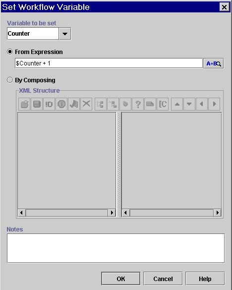
The XML document you define is stored in the workflow template definition.
Note: An XML document that is stored in a string type variable will first be converted to a string.
Controlling Program Flow
In general, you should try to control the program flow through the use of nodes and connections. In some cases, however, you may need to specify alternate paths of execution from within nodes. For example, you may have an event defined that should only be allowed to be triggered up until a certain node in the workflow, and then should be disabled. Or you may need to automatically execute a task from within a different node, depending on a condition. Most importantly, you can control whether sub-actions or even entire sub-workflows are to be performed synchronously or asynchronously by the placement of the Mark Task as Done action.
Thus, the following actions may be used for program control:
Marking a Task Done
Unless a user-assigned task is defined with a permission to allow a user to manually mark the task done at run time (for information, see Defining Task Properties), every Task node must specify the Mark Task as Done action either in its Task Properties dialog box, or in the Actions tab of a non-terminal action. For more information on using this action, see Understanding Action Types and Placement.
Figure 6-10 Mark Task as Done Dialog Box
Unmarking a Task Done
The Unmark Task Done action marks the task as not done. A task that is assigned this action becomes Active on the Worklist and can be executed again. Use this action to allow a task to be executed again in, for example, a loop or a parallel workflow.
Note: A task that is marked not done does not have its activated state triggered again. To trigger the activated state for the task, the workflow must initiate the task again. For details about task states, see Understanding Task States.
Figure 6-11 Unmark Task Done Dialog Box
Canceling a Workflow Event
Use the Cancel Workflow Event action when you want to cancel an Event node or nodes that have been defined within a workflow. This action prevents an event from being triggered after a certain point in a workflow, so you can use it as an "expiry" mechanism for the Event node. For example, in an order processing workflow, you may have an event that waits for a cancellation notice from a customer, and performs some actions accordingly; to ensure that the cancellation cannot be issued after the order is shipped, you can define the Cancel Workflow action at the point where the shipping task is executed in the workflow, to disable the order cancellation event from being triggered.
Figure 6-12 Cancel Workflow Event Dialog Box
Marking a Workflow Done
The Mark Workflow as Done action marks the current workflow as done and serves the same purpose as a workflow reaching a Done node. It could be used, for example, in a Decision node, where you would like to skip all intervening actions before the Done node and terminate the workflow at that point.
Figure 6-13 Mark Workflow as Done
Aborting a Workflow
The Abort Workflow action permanently stops a workflow that is currently in process. This action can be used in exceptional conditions where an instance must be terminated.
Note: A workflow instance that is aborted will be deleted from the database, and cannot be monitored. To specify that a workflow should simply terminate, while retaining a record of the instance, you should use a Done node or the Mark Workflow as Done action.
Figure 6-14 Abort Workflow Dialog Box
Executing a Task Automatically
You can use the Execute Task action to allow the workflow, rather than a user, to execute any task in the workflow explicitly. This action places the task in the executed state, and performs all the actions listed in the Executed tab of the Task Properties dialog box. For information on task states, see Understanding Task States.
You may use this action, for example, from within an exception handler, when you want to re-execute actions in a task node after the actions in the exception handler have been completed. Or you might use it to create a loop that would be too difficult to represent graphically.
Figure 6-15 Execute Task Dialog Box
To execute a task automatically:
Adding a Placeholder Action
The No Operation action does not affect the workflow; it simply acts as a placeholder to remind an analyst to add an action at a later time.
Figure 6-16 No Operation Dialog Box
Using Timed Operations
The following actions allow you to set up timed operations:
Embedding a Timed Sequence
You can use the Timed Event action to create a timed sequence of actions that will be triggered at an exact time and date and be optionally re-executed according to a specified schedule.
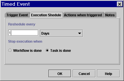
About Execution Schedules
If you want to reschedule timed events, you must specify an execution stop method, according to two options:
Executing Triggered Actions Asynchronously and Synchronously
Actions specified in a timed sequence can be performed in either a synchronous or asynchronous mode. In asynchronous mode, the sub-actions are performed in parallel, while the workflow continues to the next node. To set up the action in this way, you use the Timed Event in a Task node and mark the task containing the action done in the task node itself, or in any other type of node.
In synchronous mode, this action can serve to create a time delay in the workflow, as the workflow must wait until the trigger date and time are reached, and any sub-actions are performed, before it proceeds. To set up the action in this way, you must use the action in a Task node, and add the Mark Task as Done action to the Actions when Triggered tab of the Timed Event dialog box.
Note that in all of these cases, if you want to reschedule the timed event, you should stop the execution only when the workflow is done.
Figure 6-17 Timed Event: Trigger Event Tab
Defining a Timed Event To define a timed event: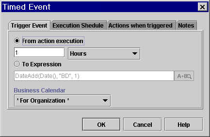
Figure 6-18 Timed Event: Execution Schedule tab
Using Sub-Workflows
Several actions allow you to specify sub-workflows that are not represented in the design area. These are described below.
Note: You can also invoke a sub-workflow by posting an XML message to an internal JMS queue to start an event-triggered workflow. For more information, see Posting an XML Message to a JMS Topic or Queue.
Calling a Sub-Workflow
You may want to organize your processes into multiple workflows to break down large, complex workflows into multiple parts, or to use sub-workflows for processes that are only invoked according to specific conditions.
You can use the Start Workflow action to start another workflow from the current one. The workflow being started is referred to as a sub-workflow, or as a called or child workflow. The workflow that starts the sub-workflow is called the calling or parent workflow.
In order for a workflow to be called, the workflow template must contain at least one template definition that contains a Called Start node, is marked active, and specifies currently valid effective and expiry dates. Only one workflow template definition within that workflow template can be started at a time, this being the most effective of the active workflow template definitions. For an explanation, see Working with Template Definitions.
Passing Parameters
If the sub-workflow has any variables defined as input parameters, this means that it expects to populate those variables with values received from the parent workflow. Thus, in the Start Workflow action properties, you must specify values to be passed as input parameters to the sub-workflow; usually these values will be taken from corresponding variables defined in the parent workflow.
Similarly, if the sub-workflow has any variables defined as output parameters, this means that the sub-workflow will pass values it has obtained or calculated back to the parent workflow. Again, in the Start Workflow action properties, you need to specify parent workflow variables that are to receive those result values.
Executing the Sub-Workflow Asynchronously or Synchronously
The Start Workflow action can be used to start a workflow in both synchronous and asynchronous modes. In synchronous mode, the calling workflow waits for the sub-workflow to complete before proceeding to the next node. To set up the action this way, you must use the Start Workflow action in a Start or Decision node, or in a Task node, and mark the task done as a sub-action of the Start Workflow action, rather than in the Task node.
In asynchronous mode, the calling workflow does not wait for the called workflow to complete, but continues to the next node, so that both workflows execute in parallel. To set up the action in this way, you can use it in a Task node, and mark the task done in the Task node itself, or use it in any other type of node, such as a Decision, Start, or Event.
Note: You can also cause another workflow to be executed both asynchronously or synchronously by posting an XML message to an internal JMS queue to trigger an event-triggered workflow. Interaction between the two workflows, including parameter passing, is accomplished through XML/JMS messaging, and control of execution is accomplished by the use of Event nodes in the parent workflow to receive responses back from the sub-workflow. In fact, if you are running WebLogic Integration in a clustered environment, this method provides better load balancing control. For more information, see Posting an XML Message to a JMS Topic or Queue.
Regardless of whether or not the parent workflow waits for the sub-workflow to finish executing before proceeding, you can also define an optional set of sub-actions that are performed when the called workflow has completed.
Tracking the Sub-Workflow
You can assign the called workflow instance ID to a variable defined in the calling workflow. The instance ID is returned as a string, so be sure that the variable you create is defined as a String type (for procedures, see Working with Variables). The calling workflow can then use the reference variable in expressions using the WorkflowVariable() function to retrieve variables from the called sub-workflow. For details about using the instance ID in the WorkflowVariable() function, see Obtaining Run-time Workflow Data.
Figure 6-19 Start Workflow Dialog Box
Note: The variable must be a string type.
Figure 6-20 Set Parameter Dialog Box
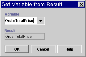
Figure 6-21 Set Variable from Result Dialog Box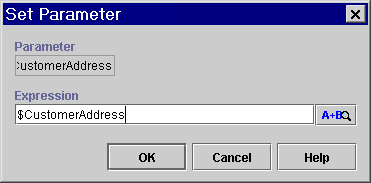
Embedding a Conditional Sequence
The Evaluate Condition action functions in the same way as a Decision node, that is, to evaluate a conditional expression at run time and perform alternative sequences of sub-actions depending on the result. Normally, you should use a Decision node to accomplish this type of flow. However, there may cases where you want to embed a conditional sub-workflow within a main workflow, by specifying a conditional set of actions inside another node, rather than as a distinct node on its own. This is necessary in cases where there is no other way to specify a condition, such as in an Exception Handler.
You define a series of actions to be performed if the condition evaluates to true, and/or a series of actions to perform if the condition evaluates to false.
Figure 6-22 Evaluate Condition Dialog Box
Monitoring Run-Time Status
You can use two actions for workflow monitoring purposes:
Making an Audit Entry
WebLogic Integration provides a default audit facility whereby all major user interactions and changes are published to a JMS topic and to a log file, myserver.log, located in the logs directory of the active WebLogic Integration domain on the server.
You can use the Make Audit Entry action in any node in your workflow to define additional run-time workflow information you would like to publish to the audit log over the course of a workflow. The date and time of each entry is noted, and you define an expression that will provide the data you want to record at run time, containing variables, functions or constants. For example, you could use the CurrentUser() function in a task that is assigned to a role, to record the user who executed it. (For information on functions that return run-time workflow information, see Obtaining Run-time Workflow Data.)
Note: Auditing must be enabled in the Template Definition properties dialog box for the workflow for this action to take effect. For further information, see Creating a Workflow Template Definition.
Figure 6-23 Make Audit Entry Dialog Box
Setting Up a Workflow Comment
You can use the Set Workflow Comment action to specify a comment for the workflow instance. The comment will be displayed in the Comment column of the Workflow Instances dialog box of the Studio when the action is executed at run time (for more information, see Working with Workflow Instances). The text is typically informative and indicates the status of the workflow at that point.
Figure 6-24 Set Workflow Comment Dialog Box
Setting Up Manual Tasks
You can use the following Task actions to assign manual tasks or interact with WebLogic Integration Worklist or custom client application users.
Guidelines for Placement of Task Actions
When assigning manual tasks, follow these guidelines for action placement:
Assigning a Task to a User
Use the Assign Task to User action to assign a specified task to an individual user. Assigning a task to a user causes a notification to be sent to the user who views and executes the task from the Worklist or custom client application. For more information about the Worklist application, see Using the WebLogic Integration Worklist
.You can specify a particular user to whom to assign the task, or you can specify a role member, which causes the system to determine the user with the fewest pending tasks among all users belonging to a particular role at run time. The system then assigns the task to that user. The user or role can be specified as a constant or taken from a workflow expression to be provided at run time.
Figure 6-25 Assign Task to User Dialog Box
Assigning a Task to a Role
Use can use the Assign Task to Role action when it is not desirable to assign a task to a particular user. Assigning a task to a role allows any user who belongs to the role to view and execute the task, although there is no explicit notification of the task in the Worklist.
To assign a task to a role, you specify the role name or provide an expression to determine the role at run time.
Figure 6-26 Assign Task to Role Dialog Box
Assigning a Task Using a Routing Table
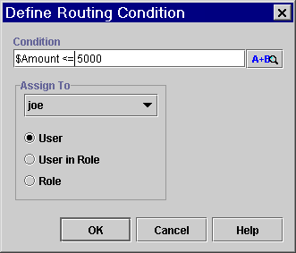
You can assign a task to different users or roles depending on a set of conditions. A routing table consists of a sequence of one or more routing conditions. A routing condition specifies a potential assignee (user or role) for the task, together with a specification of the conditions under which the assignment should be made. When the action is executed at run time, the system evaluates each condition in sequence until it encounters one that yields a True result. If such a condition is encountered, the task is assigned to the corresponding user or role, and any subsequent conditions are ignored.
Note: If no routing condition is satisfied, a run-time exception occurs.
If you would like to route all tasks for a particular user or role for a specific period of time, rather than according to a condition, you create a routing specification for an organization. For more information, see Administering Task Routings.
Figure 6-27 Assign Task Using Routing Table Dialog Box
To assign a task using a routing table: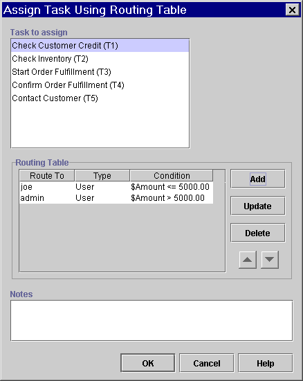
Figure 6-28 Define Routing Condition Dialog Box
Setting a Task Due Date
You can use the Set Task Due Date action to set the due date by which a task should be executed. The due date is displayed to the Worklist or custom client user to whom the task has been assigned. You can express the due date in minutes, hours, days, weeks, or months, or as an expression to determine the date and time at run time.
You can also use this action for non-manual tasks, without the use of the Assign Task to User action, to specify actions to be performed in parallel after a certain date, or to introduce a time delay into a workflow.
Executing Overdue Actions Asynchronously and Synchronously
If the task is not executed by the due date, you can specify sub-actions that should be performed after the due date, in either a synchronous or asynchronous mode. In asynchronous mode, the sub-actions are performed in parallel, while the workflow continues to the next node. To set up the action in this way, you mark the task containing the action done in the Task node itself. This is normally how the action is used for manually assigned tasks.
In synchronous mode, this action can serve to create a time delay in the workflow, as the workflow must wait until the due date is reached, and any overdue actions are performed, before it proceeds. To set up the action in this way, you place the action in a Task that is assigned to a user or not, and mark the task containing the action done by adding the Mark Task as Done action to the Overdue Actions tab of the Set Task Due Date dialog box.
Figure 6-29 Set Task Due Date Dialog Box
Setting a Task Comment
You can use the Set Task Comment action to set a comment for the task instance, which displays a text message to a user viewing the task in the Worklist or the Studio when the action is executed at run time. The text typically provides information or instructions for manual work which the user is asked to perform. The text message is displayed in the Comment column next to the task in the task list in the Worklist application, or in the Workflow Instances or Worklist dialog boxes in the Studio. (For more information, see Monitoring Workflows.
Figure 6-30 Set Task Comment Dialog Box
Setting a Task Priority
You can use the Set Task Priority action set a task priority to Low, Medium, or High. The priority has no effect on how the node or its actions are executed at run time, but is simply displayed to Worklist users, who can execute and sort their tasks accordingly.
Since you can set a priority for the current task in the Task's properties dialog box, you may wish to use this action as the result of a condition to specify the priority of a task elsewhere in the workflow.
Figure 6-31 Set Task Priority Dialog Box
Unassigning a Task
You can use the Unassign Task action to remove the current task assignment. The task is no longer assigned to a user or role. You may wish to unassign a task as a result of a condition.
Figure 6-32 Unassign Task Dialog Box
Sending an XML Message to a Client Application
Once you have assigned a task to a user, you can use the Send XML to Client action to communicate between a workflow and the Worklist or custom client application by sending an XML document to the client. The client application must be programmed to identify the XML document, perform the appropriate action, and return an XML document in response to the workflow. For the Worklist application, you can send XML messages to display message prompts and forms to users, and to call custom components or executable programs on the client system. For information on developing custom client applications, see Programming BPM Client Applications.
Note that the Send XML to Client action does not actually specify the client machine or application to which the XML is being sent. Thus, you must first assign a task to a user or role, and the XML message will be sent to the client that executes the task. For more information, see Setting Up Manual Tasks.
Sending a Message Asynchronously or Synchronously
You can send an XML message to a client application asynchronously or synchronously. In synchronous mode, the workflow waits for a response from the client before proceeding to the next node. To set up the action this way, you must use mark the Task containing the action done as a sub-action on the Callback Actions tab of the Send XML to Client dialog box, rather than in the Task node.
In asynchronous mode, the workflow does not wait for a response from the client, but continues to the next node, while any operations on the client execute in parallel. To set up the action in this way, mark the task done in the Task node itself.
Extracting Data
If your application responds to the workflow by sending a return XML message, you must create variables to store the data returned by the response document (see Working with Variables for procedures), and initialize those variables by using XPath expressions (or dot notation) to retrieve data values from the response XML document. If your application uses JMS properties in its messages, you can also retrieve this data by using the EventAttribute() function. (For more information, see Extracting Run-Time Event Data.)
Defining the Send XML to Client Action
The following procedure is generalized for any non-Worklist application. For complete information on sending an XML message to the Worklist, see Sending an XML Message to the Worklist Application. For detailed information on working with type-specified XML documents, see Working with Type-Specified Documents.
Figure 6-33 Send XML to Client Dialog Box
To send an XML message to a client: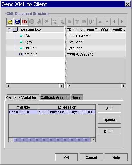
Note: The system-generated actionid element and its value are used at run time to identify the Send XML to Client action. The actionid element must be the first child element of the root element. Do not move, delete or edit the actionid element, and do not add any sub-elements to it.
For detailed procedures for all these options, see Composing and Editing XML Documents.
The XML document you define is stored in the workflow template definition.
Figure 6-34 Workflow Variable Assignment Dialog Box
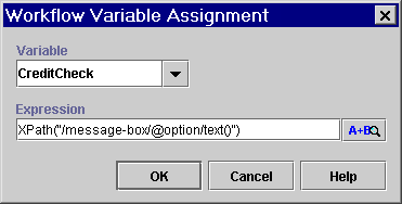
 to invoke the XPath Wizard, from which you can generate XPath expressions automatically from a sample incoming document. For information, see Creating XPath Expressions Using the XPath Wizard.
Sending an XML Message to the Worklist Application
The Worklist client application is designed to perform an action in response to an XML document that conforms to four pairs of predefined Document Type Definition (DTD) files, which allow you to do the following:
The four pairs of predefined DTD files are located in the following directory of your WebLogic Integration server installation:
/bea/wlintegration2.1/docs/apidocs/com/bea/wlpi/common/doc-files
Each pair has one DTD file for a request to the Worklist client, and another DTD file for a response from the Worklist client. The following table lists the predefined DTD files, and the actions performed by the Worklist application when it receives an XML document that conforms to one of the request DTD files.
Note: If you will be accessing these DTDs often, you may want to import them into the repository for convenient retrieval. For procedures, see Managing Entities in the Repository.
For each response received from the client, you will need to create a variable in which to place the value returned by the response. Most of these will be string-type variables. For procedures for creating variables, see Working with Variables.
The following sections provide detailed descriptions of the required document structure for each DTD pair.
Displaying a Message Prompt to a User
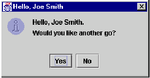
You can use the ClientMsgBox DTDs to display a message box to the Worklist user, as in the following example.
Figure 6-35 Example Message Prompt
The request DTD requires a document with the following structure. Listing 6-1 ClientMsgBoxReq XML Document Structure All elements and attributes are required, and are described below.
Table 6-3 ClientMsgBoxReq Elements and Attributes
<message-box title="text" style="{plain|information|question|warning|error}" options="{ok|ok_cancel|yes_no|yes_no_cancel}">
text
   <actionid>	provided by default	</actionid>
</message-box>
The response document provides the response of the user to the message box, according to the button selected. The response DTD requires the following structure.
Listing 6-2 ClientMsgBoxResp XML Document Structure
<message-box option="{ok|yes|no|cancel}" /> The element and attribute are required, and are described below, along with the expression required to return the value to a workflow variable.
Table 6-4 ClientMsgBoxResp Elements and Attributes
Displaying a Form to a User
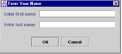
You can use the ClientSetVars DTDs to display a form to the Worklist user, as in the following example.
Figure 6-36 Example Form
The request DTD requires a document with the following structure. Listing 6-3 ClientSetVarsReq XML Document Structure All elements and attributes are required. There must be at least one <variable> element and as many additional <variable> elements as you like. Element and attributes are described below.
Table 6-5 ClientSetVarsReq Elements and Attributes
<set-variables title="text">
text
   <actionid>provided by default	</actionid>
   <variable name="variable name" prompt="text" />
   [<variable name="variable name" prompt="text" />]
</set-variables>
The response document provides the responses of the user to each of the entry fields. The response DTD requires the following structure.
Listing 6-4 ClientSetVarsResp XML Document Structure
<set-variables>
   <variable name="variable_name_1">response_1</variable>
   [<variable name="variable name_2">response_1</variable>]
   .
   .
   .
</set-variables>
All elements and attributes are required, and the number of <variable> elements should correspond to the number used in the request document. Elements and attributes are required, and the expression required to return the value to a workflow variable, are described below.
Table 6-6 ClientSetVarsResp Elements and Attributes
Calling an Executable Program on the Client
You can use the ClientCallProgram DTDs to call a program on the Worklist client. The request document requires the following structure.
Listing 6-5 ClientCallProgramReq XML Document Structure
<call-program name="name" mode="{sync|async}">
    <actionid>	provided by default	</actionid>
    [<parm>parameter_1</parm>]
    .
    .
    .
    [<env-var name="name">environment variable
      definition_1</env-var>]
    .
    .
    .
</call-program>
All elements and attributes are required, except the <parm> and <env-var> elements, which are optional. You can specify zero or more <parm> or <env-var> elements.
Table 6-7 ClientCallProgramReq Elements and Attributes
The response DTD requires the following structure.
Listing 6-6 ClientCallProgramResp XML Document Structure
<call-program exit-value="value" />
The element and attribute are required, and are described below.
Table 6-8 ClientCallProgramResp Element
Calling a Custom Worklist Extension on the Client
You can use the ClientCallAddIn DTDs to call a custom extension to the Worklist client. The request document requires the following structure.
Listing 6-7 ClientCallAddInReq XML Document Structure
<call-addin name="name" mode="{sync|async}">
    <actionid>	provided by default	</actionid>
    [<parm>parameter_1</parm>]
    .
    .
    .
</call-addin>
All elements and attributes are required, except the <parm> element, which is optional. You can specify zero or more <parm> elements.
Table 6-9 ClientCallAddInReq Attributes and Elements
The response document is optional. Elements are optional and can consist of any number of custom elements and attributes you define.
Listing 6-8 ClientCallAddInResp XML Document Structure
<call-addin>
	[<tag_name_1 attribute_name_1="attribute_value"
         . . .>value</tag_name_1>]
       .
       .
       .
</call-addin>
Elements are described below.
Table 6-10 ClientCallAddInResp Elements and Attributes
|
Element or Attribute |
Description |
Valid Values |
Expression Required to Extract Value |
|---|---|---|---|
|
Any element name |
Can consist of any number of attributes. |
Custom-defined. |
XPath("/call-addin/path/text()") |
Sending E-Mail Messages
You can use the Send E-Mail Message action to send an e-mail message to a user of the WebLogic Integration system or even to an outside party. Internet standard SMTP protocol is used to transmit the message.
You can compose an e-mail message in any character set that your operating system supports at design time, and specify the character set to be used by the server at run time to the send the message. In an English locale, the default character set used by the server is cp1252, the default character set used by the Java Virtual Machine, but you can specify any character set supported by the Java language. For a list of these, see http://java.sun.com/j2se/1.3/docs/guide/intl/encoding.doc.html.
Note: This action requires that your e-mail server be properly configured during or after the WebLogic Integration server installation process. For information on configuring mail server properties after installation, see "Customizing Mail Session Properties" in Customizing WebLogic Integration in Starting, Stopping, and Customizing BEA WebLogic Integration.
Figure 6-37 Send E-Mail Message Dialog Box
Note: The encoding you use to input characters is independent of the setting in the Mime Charset field, and is determined by your operating system and locale.
Figure 6-38 Send E-mail Message Dialog Box: To Tab
Figure 6-39 Mail Recipient Dialog Box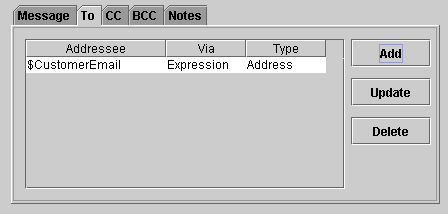
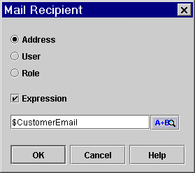
For more information on workflow functions and constructing expressions, see Using Workflow Expressions.
Invoking Components
You can call software components such as EJBs, Java classes, and executable programs, and pass input and output parameters between the workflow and the components directly, by using the following actions:
Calling an Executable Program on the Server
You can use the Call Program action to call an executable program on the WebLogic Integration server. This action is always executed asynchronously, meaning that any actions following this action in the workflow are executed simultaneously, without waiting for the called program to complete.
Figure 6-40 Call Program Dialog Box
To call an executable program on the server:
If you are running a DOS script file, such as a.cmd or .bat file that does not include any DOS shell-specific commands (e.g., echo), do one of the following:
If you are running a DOS script file, such as a.cmd or .bat file that includes DOS shell-specific commands (e.g., echo), enter the following:
c:\winnt\system32\cmd
If you are running a DOS script file, such as a.cmd or .bat file that includes DOS shell-specific commands (e.g., echo), enter the following:
"/c start c:\\path\\filename.extension expression"
Calling a Business Operation
You use the Perform Business Operation action to call a method on a Java component, such as an EJB or Java class, that performs a business activity.
The business operation you want to invoke must already be defined. Additionally, Java Object, Session EJB, and Entity EJB variables must already be defined to store references to the Java class or EJB instances whose methods are being called by the business operation. For details about defining business operations, see Configuring Business Operations. For details about defining variables, see Working with Variables.
Also note that before you can perform business operations that call methods on EJBs or non-static methods on Java classes, you must first call the business operation that serves to create an instance of the Java class or EJB on the WebLogic Integration server, according to the following rules:
When you perform the business operation that creates the instance, you assign a reference to the instance to a variable, called an instance variable. You then identify the instance variable that references the EJB or Java class instance when calling other business operations representing methods contained in the same EJB or class. More information is provided in the following sections.
Calling the Business Operation to Create an EJB or Java Class Instance
When you call a business operation that creates an EJB or Java class instance, you must assign a reference to the instance to a variable of the same data type, as follows:
Figure 6-41 Perform Business Operation Dialog Box
To call a business operation to create an EJB or Java class instance:
Calling Other Business Operations
Once the Perform Business Operation for the create() or constructor method of an EJB or Java class has been added to a node, you can add other business operations that invoke methods on the same class or EJB.
For methods that take parameters and return results, such as, for example, a calculated total price, you also need to create a variable that will store the value returned by the business operation. Be sure that this variable is of the same type as that specified by the method.
Figure 6-42 Perform Business Operation Dialog Box
To call other business operations:
Posting an XML Message to a JMS Topic or Queue
Use the Post XML Event action to send an XML message to a specified destination to trigger an event. This action embeds an XML document in the workflow and sends the XML content inside a JMS message that can be posted to an external JMS queue or topic for processing by an external application, or to an internal queue for processing by another workflow.
Note: If you are running WebLogic Integration in a clustered environment, posting an XML event to initiate another workflow is preferred over calling the workflow directly with a Start Workflow action, as this method provides better load balancing control.
You can compose the XML document to be sent, or import an existing XML document from the XML repository, a file on disk, or a URL. You can also specify the document to be sent as a variable in which the XML content can be specified at run-time.
In addition to XML message content, the Post XML Event action also inserts JMS headers and values into the message according to options that you specify in the action's properties. For information on standard JMS header fields in WebLogic Server, see "WebLogic JMS Fundamentals" in Programming WebLogic JMS at the following URL: http://download.oracle.com/docs/cd/E13222_01/wls/docs61/jms/fund.html
JMS messaging options are described in the following sections.
Posting an Event Asynchronously or Synchronously
You can set up your XML event to function in an asynchronous or synchronous manner in relation to workflows or other components that are configured to consume outgoing messages. You do this using Event nodes in the workflow initiating the communication to receive confirmation messages back from the recipient workflows.
By default, the Post XML Event action is asynchronous in that it simply posts a message in a "fire and forget" fashion, while the workflow proceeds to the next action. Thus, if you would like to trigger another workflow or application to be executed in parallel, and the calling workflow does not need to receive any communication back from the called workflow or application, simply use the action as is.
If you would like the calling workflow and the called workflow or application to execute in parallel, but the calling workflow does expect to receive a message back from the called workflow or application, you can set up an Event node in the calling workflow that receives the message in a "just in time" fashion. That is, you can set up an Event node only at the point in the workflow where the data returned by the called workflow or application is required. These two scenarios are illustrated in the following figure.
Figure 6-43 Posting an XML Event Asynchronously
If you want to post the XML event in a purely synchronous fashion, that is, to force the calling workflow to wait until the called workflow or application has finished executing before it proceeds, you must set up the called workflow or application to send a message when it finishes executing, and place an Event node that listens for this message immediately after the Post XML Event action in the calling workflow. This design is illustrated in the following figure. Figure 6-44 Posting an Event Synchronously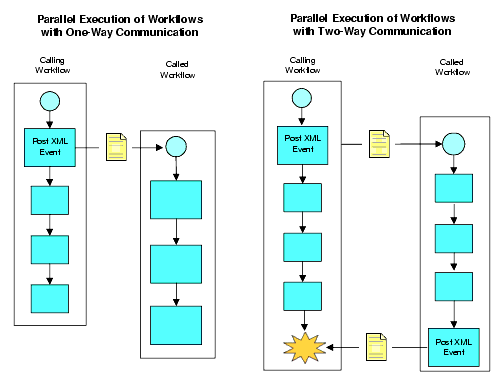
Understanding JMS Messaging Options The following sections discuss the various JMS messaging options that are available from within the Post XML Event dialog box. Destination You can specify an internal JMS queue to trigger an Event node in the current workflow or in another one, or to start another workflow defined with an event-triggered Start. (For details about event triggers in Start and Event nodes, see Defining Event And Event-Triggered Start Properties.) The JNDI name of the internal JMS queue, to which messages are sent by default, is com.bea.wlpiEventQueue. If you have configured other queues in WebLogic Server, you can also specify an alternate queue name. (For more information on setting up alternate message queues for WebLogic Integration, see "Configuring a Custom Java Message Service Queue" in Customizing WebLogic Integration in Starting, Stopping, and Customizing BEA WebLogic Integration.) You can also send the XML message to an external JMS topic or queue to communicate with an external application that subscribes to the JMS topic you specify, or with a specific application that is the JMS queue receiver. Headers JMS messages contain a standard set of header fields that are always transmitted with the message. In addition to the JMSDeliveryMode, JMSDestination, JMSPriority, and JMSExpiration (time to live) headers that are automatically inserted by the options available in the Post XML Event dialog box, you can also add property fields and values to your outgoing messages for application-specific information to specify information in the message that is not appropriate for the body of the message. For example, if you are using XML messaging to trigger another workflow, you may wish to use a property field to specify the name of the organization in which the workflow should start. JMS message properties are name-value pairs. The name can be almost any string that is a valid identifier in the Java language. The value can be any one of the following types: Boolean, Byte, Short, Int, Long, Float, Double, or String. For more information about JMS header and property fields, see "WebLogic JMS Fundamentals" in Programming WebLogic JMS at the following URL: http://download.oracle.com/docs/cd/E13222_01/wls/docs61/jms/fund.html If you use ordered or addressed messages, WebLogic Integration inserts property fields for an order key you specify, for ordered messages, and workflow instance IDs you specify, for addressed messages, based on the values you enter on the Addressing tab of the Post XML Event dialog box options. However, you can also manually insert two additional supported properties: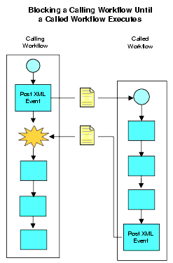
This feature can be useful when you need to consolidate a list of workflow instances or template names that have entered into a conversation with the current workflow and which you want to pass via a single message to an external application.
If you intend the message to be received by another workflow, the receiving workflow can use the EventAttribute() function in an event key expression or in a variable initialization in a Start or Event node to retrieve the information you specified in the property field. If multiple instance IDs or template names are specified, you must assign the result of the function to a variable defined as a Java object data type.
For more information on event key expressions, see Configuring Event Keys. For more information on initializing variables from event data, see Initializing Variables from Event Data. For details about the EventAttribute() function, see Extracting Run-Time Event Data.
Delivery Mode
You can specify whether a message is to be persistent or non-persistent. Persistent messages are written to a database table and are not lost even if the JMS server fails. The message is delivered again after the server recovers. Non-persistent messages can be lost if the JMS server fails. The message is not delivered again after the server recovers. The default delivery mode is persistent.
Time to live
Whether a message is persistent or non-persistent, you can specify an expiry time for your message. If the message is not delivered before the expiry time, it is discarded. This option is useful for messages that should not be delivered after a certain time, such as a stock bid. The time to live is expressed in milliseconds. For example, if you want the message to be available for 1 hour, you specify a value of 3600000 (1000 milliseconds x 60 seconds x 60 minutes). The default value of 0 (zero) indicates that the message will not expire.
If you specify an expiry time for an addressed message, the message is persisted until the message is successfully delivered to all specified recipients, or until it expires, whichever comes first.
Priority
You can assign a priority level from 0 to 9. Levels 0-4 are normal priority. Levels 5-9 are expedited priority. Messages with an expedited priority are delivered ahead of messages with a normal priority. You would typically use an expedited priority for an alarm or shutdown message. The default priority level is 4.
Note that priority overrides ordered messaging, so that you must specify the same priority level for all messages with the same order key. The recommended setting is to keep the default of 4.
To use other priority levels, you must first configure a destination key in WebLogic Server. For more information, see "Managing JMS" in the WebLogic Server Administration Guide at the following URL: http://download.oracle.com/docs/cd/E13222_01/wls/docs61/adminguide/jms.html.
Transaction Mode
You can specify whether you want the message to be sent immediately, or when the current transaction containing the Post XML Event action commits. Sending the message immediately sends the message whether or not the transaction completes. Sending the message on commit ensures that the message is sent only if the transaction completes successfully and a commit is issued. If the transaction is unsuccessful and is rolled back, the message is not sent. The default is when the transaction commits. For more information on workflow transaction boundaries, see Understanding the BPM Transaction Model in Programming BPM Client Applications.
Addressed Messaging
You can use addressed messaging to guarantee that a response message is delivered to a particular workflow instance that has begun a conversation with the current workflow (either by calling it via the Start Workflow action, or by triggering a Start or Event node contained within it via a previously sent XML message) — even if the receiving Event node in the instantiated workflow has not yet been activated in the flow. (For information on node activation, see Understanding the BPM Transaction Model in Programming BPM Client Applications.)
When you use addressed messaging, you typically provide a list of workflow instance IDs to which the message should be delivered. These will have been sent from the originating workflows via a WorkflowAttribute("InstanceID") expression embedded in an XML message or as a parameter passed to the workflow via a Start Workflow action, and then extracted and stored in a variable by a previous node in the current workflow. The list of instance IDs, then, is typically a comma-separated list of variables containing the appropriate IDs. The message will only be delivered to the instances specified in this list.
Note: Workflow instance IDs are stored as strings, so if you want to create variables to hold instance ID values, be sure that these variables are created as string types. For more information on the workflow attribute functions, see Obtaining Run-time Workflow Data.
Note that if you specify a time to live, the message will persist until the message has been delivered to all specified recipients, or until the message expires, whichever comes first.
Ordered Messaging
You can specify an order key that guarantees that messages are processed sequentially by the same event listener in the order in which they are received. As an example, if an order processing system receives requests to create an order and to update or cancel an order, you may want to guarantee that create request messages are processed first.
An order key must be an integer value, and the value must be the same for each event that you want processed in the order in which it is received. For example, if two events are posted at the same time, and you want them processed in the order in which they are received, you would enter the same order key value, such as the integer value of 8, for each event. Ordered messages must also be sent to the same JMS queue.
Note that ordered messaging is incompatible with message priority, so that if you use an order key, you must set the same priority level for all messages with the same order key. The recommended setting is to keep the default of 4.
Defining the Post XML Event Action
To define the XML event:
Figure 6-45 Post XML Event Dialog Box: XML Message Tab
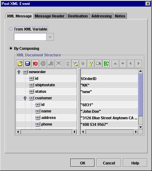
The XML document you define is stored in the workflow template definition.
Note: For more information on constructing expressions, see Using Workflow Expressions.
Figure 6-46 Post XML Event Dialog Box: Destination Tab
Figure 6-47 Set JMS Properties Dialog Box
Figure 6-48 Post XML Event Dialog Box: Message Header Tab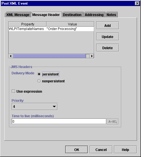
Note: If you specify an order key for ordered messaging, leave the default value of 4.
Figure 6-49 Post XML Event Dialog Box: Addressing Tab
Note: If you specify a Time to live in the Message Header area, the message persists only for the time you specified.
Note: If you specify an order key, leave the default value message priority value of 4.
Transforming XML Documents
Extensible Stylesheet Language Transformations (XSLT) define rules for translating an XML document into another XML or non-XML document. An XSL template document specifies which elements in the input XML document are to be transformed, and how they are to be transformed.
The XSL Transform action provides a way for you to specify an input XML document that is to be transformed, an XSL template document that specifies the details of the transformation, and an output variable that will contain the transformed document. The actual transformation occurs at run time, and is performed by the XSL transformation engine bundled with WebLogic Server.
The input document can contain workflow expressions. If it does, the process engine resolves the expressions, and replaces the expression with the result before the transformation occurs. Similarly, the XSL template document can contain references to workflow variables. If it does, the process engine resolves the references, and replaces the reference with the appropriate value before the transformation occurs.
Note that the input document is specified as an expression that identifies the location of the document at run time. This expression could include the name of a workflow variable in which you have stored an XML document. In this case, you will need to have created an XML-type variable (for information, see Working with Variables), and assigned an existing or incoming XML document to it previously in the workflow—one way of doing this is by using the Set Workflow Variable action; see Setting a Variable Value for procedures.
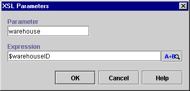
The XSL template document, or transform document, can be an entity stored in the repository (for more information, see Managing Entities in the Repository), or you can use an expression that locates the document at run time. If the XSL entity in the repository or the XSL document to be located at run time takes parameters, you can also specify expressions that will supply values for those parameters at run time.
The output document must be stored in an XML variable which you can create ahead of time. See Creating a Variable for procedures.
Figure 6-50 XSL Transform Dialog Box
Note: For more information on constructing expressions, see Using Workflow Expressions.
Figure 6-51 XSL Parameters Dialog box
Handling Exceptions
All actions pertaining to exception handling are discussed in Handling Workflow Exceptions.

|

|

|
|
|
|
Copyright © 2001 BEA Systems, Inc. All rights reserved.
|