3.3 Power on the System the First Time

Before powering on the system for the first time, it is necessary to inspect the machine, and connect the power cords. This section contains the following topics:

3.3.1 Inspect the Machine After It Is in Place

The following procedure describes how to visually examine the Exalogic machine physical system after it is in place, but before power is supplied:

  1. Check the rack for damage.

  2. Check the rack for loose or missing screws.

  3. Check your Exalogic machine for the ordered configuration. Refer to the Customer Information Sheet (CIS) on the side of the packaging.

  4. Check that all cable connections are secure and firmly in place as follows:

    1. Check the power cables. Ensure that the correct connectors have been supplied for the data center facility power source.

    2. Check the network data cables.

  5. Check the site location tile arrangement for cable access and airflow.

  6. Check the data center airflow that leads in to the front of the Exalogic machine.

See Also:

Ventilation and Cooling Requirementsfor more information

3.3.2 Connect the Power Cords

The following procedure describes how to connect power cords to the Exalogic machine:

  1. Open the rear cabinet door.
  2. Ensure that the correct power connectors have been supplied.
  3. Unfasten the power cord cable ties. The ties are for shipping only and are no longer needed.
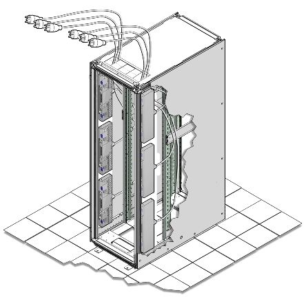
  4. Route the power cords to the facility receptacles either above the rack or below the flooring, as shown in Figure 3-9 and Figure 3-10.
  5. Secure the power cords in bundles, as shown in Figure 3-9.
  6. Plug the PDU power cord connectors into the facility receptacles.

Figure 3-9 Power Cord Routing from the Bottom of the Rack
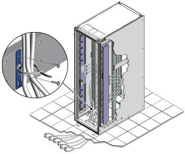
Description of Figure 3-9 follows
Description of "Figure 3-9 Power Cord Routing from the Bottom of the Rack"

Figure 3-10 Power Cord Routing Example from the Top of the Rack
Description of Figure 3-10 follows
Description of "Figure 3-10 Power Cord Routing Example from the Top of the Rack"
3.3.3 Power On the Exalogic Machine

The following procedure describes how to power on the Exalogic machine:

  1. Ensure that each of the three main power cords is connected.
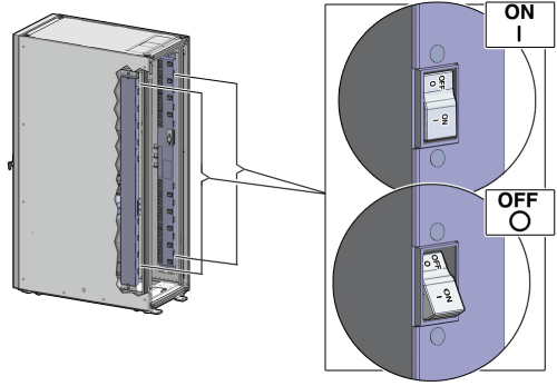
  2. Switch on the six power distribution unit (PDU) circuit breakers located on the rear of the main PDU (PDU A) inside the Exalogic machine. The circuit breakers are on the rear of the Exalogic machine cabinet as shown in Figure 3-11. Press the ON (|) side of the toggle switch.

    Note:

    The 24 kVA PDU has 4 plugs, and the 15 kVA PDU has 2 plugs. In either case, you can use the instructions described in this section to power on your Exalogic machine.

    Figure 3-11 PDU Switch Locations

    Description of Figure 3-11 follows
    Description of "Figure 3-11 PDU Switch Locations"
  3. Wait 3 to 5 minutes for all Oracle Integrated Lights Out Manager (ILOM) service processors to boot.
  4. Open the front cabinet door.
  5. Verify that server standby power is on for compute nodes, InfiniBand gateway switches, and storage appliance in the Exalogic machine.

    When power is delivered to the receptacles at the rear of the server chassis, standby power is made available by the power supplies. When standby power is distributed to the chassis, the service processor (SP) powers on and starts up to manage the system. The main power is supplied for the remainder of the chassis and fans when the power button on the front of the server chassis is pressed. The power button is disabled while the SP is starting. The start-up state is indicated by a steady one second on, one second off blinking pattern of the Power/OK LED on the front of the system. After the SP has started, the power button is enabled and the system is placed in standby power mode.

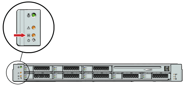
    In standby power mode, the Power/OK LED on the front panel blinks green in a 0.1 second on, 2.9 seconds off pattern, as shown in Figure 3-12.

    Figure 3-12 Exalogic Compute Node LED Lights

    Description of Figure 3-12 follows
    Description of "Figure 3-12 Exalogic Compute Node LED Lights"
  6. Verify that the main power is on for each compute node.

    In main power mode, the Power/OK LED on the front panel blinks in a one second on, one second off pattern while the system BIOS starts. After BIOS initialization completes and the operating system begins to start, the Power/OK LED illuminates and remains a steady green.

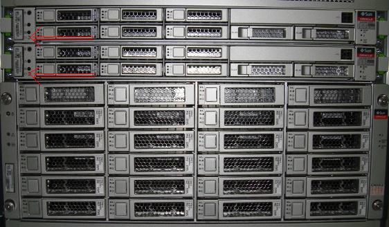
  7. Press the soft switches located on the front of the two storage heads in the storage appliance, as shown in Figure 3-13. In addition, see Figure 3-14.

    Figure 3-13 Soft Switches on the Server Heads in the Sun ZFS Storage 7320 appliance

    Description of Figure 3-13 follows
    Description of "Figure 3-13 Soft Switches on the Server Heads in the Sun ZFS Storage 7320 appliance"

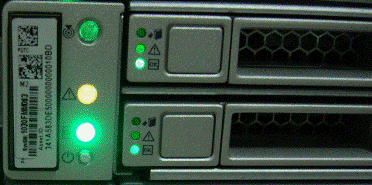
    Figure 3-14 shows the soft switch and LED lights on each of the server heads in the storage appliance.

    Figure 3-14 Soft Switch and LED Lights on Server Heads

    Description of Figure 3-14 follows
    Description of "Figure 3-14 Soft Switch and LED Lights on Server Heads"
  8. Wait 3-5 minutes for the storage appliance to initiate NFS services, daemons, and basic services.

    Tip:

    You can ping the IP address assigned to the storage appliance to verify whether the system is up and running. For the default NET0 IP addresses, see Default IP Addresses and Ports.

    Alternatively, you can try to launch the administration console for the storage appliance. Before you can ping the IP address or launch the administration console, you must connect a laptop to the rack, as described in Connect a Laptop to the Exalogic Machine.

  9. After making sure that the storage appliance is up and running, press the soft switches located on the front of the compute nodes in your Exalogic machine, as shown in Figure 3-13. After power-on, the LED indicators turn green, as shown in Figure 3-14.

    Note:

    If you are using an Exalogic machine full rack, you must switch on thirty compute nodes. If you are using an Exalogic machine half rack, you must switch on sixteen compute nodes. If you are using an Exalogic machine quarter rack, you must switch on eight compute nodes.

  10. Verify that power is applied to the Cisco Ethernet switch.

    Note:

    The Ethernet switch is inside a vented filler panel in Unit 25 of the rack.

  11. Verify that power is applied to the Sun Network QDR InfiniBand Gateway Switches.

    Note:

    The gateway switches are inside vented filler panels. If you are using an Exalogic machine full rack, verify that power is supplied to the four gateway switches included in the Exalogic machine. If you are using an Exalogic machine half rack, verify that power is supplied to the two gateway switches included in the Exalogic machine. If you are using an Exalogic machine quarter rack, verify that power is supplied to the two gateway switches included in the Exalogic machine.

  12. Optional: Verify that power is supplied to the Sun Datacenter InfiniBand Switch 36.

    Note:

    The Sun Datacenter InfiniBand Switch 36 is inside a vented filler panel when deployed. This spine switch is used in multirack configuration scenarios only and it must be purchased separately. A multirack configuration consists of an Exalogic machine connected to another Exalogic machine or an Oracle Exadata Database Machine.