Creating and Viewing Exalogic Reports
By using reports, you can view the Exalogic rack setup, including the asset details related to the firmware. Reports provide information about your assets, such as job history, firmware, OS updates, and problems. Reports are created in PDF and CSV formats. Reports can be exported or used to launch jobs on targeted assets.
Creating an Exalogic System Report
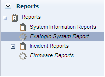
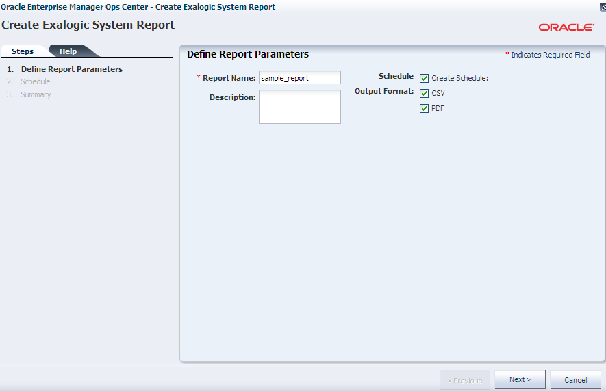
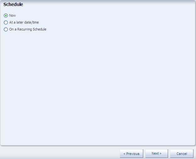
To create an Exalogic System Report in Exalogic Control, complete the following steps:
Viewing the Exalogic System Report
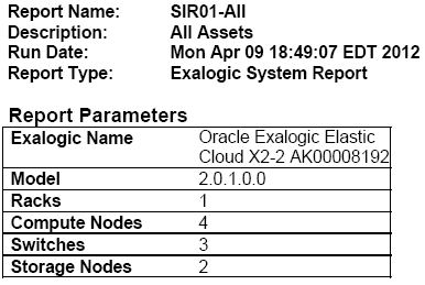
You can view existing reports. The Exalogic report contains the following sections:
Report Parameters
The Report Parameters section displays the name and model of the Exalogic system. It also displays the number of assets in the rack by their types, such as compute nodes, switches, and storage nodes in the system.
Summary Table
The Summary Table is a list of all tables in the report. It displays the number of records for each table.
System Control Software Table
The System Control Software Table lists the following:
-
Exalogic Control software components
-
Versions of Exalogic Control software components
-
Descriptions
-
Names of VMs running Exalogic Control
-
Names of Oracle VM Servers hosting Exalogic Control VMs
Compute Nodes Table
The Compute Nodes Table displays the setup of the racks, such as the following:
-
Type of asset
-
Name of asset (compute node)
-
Firmware version, such as BIOS, service processor, and HCA adapter
-
Version and location of the asset in the rack
Switches Table
The Switches Table displays the name of the switch node, type of switch, firmware version, and location of the switch in the rack with the slot number where it is placed.
Storage Appliances Table
The Storage Appliances Table displays the name of the compute node, version of the service processor firmware, and the location of the appliance with the slot number where it is placed in the rack.
Power Distribution Units Table
The Power Distribution Units Table displays the PDUs and their firmware version.
Validation Table
The Validation Table displays the validation result of the rack. A baseline check is performed against the known schema for the rack. The Expected Component column in the table displays the expected component if the placed component in the slot does not match the schema when the baseline check is performed.


