| C H A P T E R 1 |
|
Installing the Server Hardware |
This chapter covers the hardware installation of the Sun Blade X6440 server module and service processor connection and verification procedures. This chapter contains the following topics:
Before you begin this installation procedure be sure you have the following:
After unpacking your Sun Blade X6440 server module, perform the following tasks to install it into a modular chassis. You must have already installed the chassis before starting the installation.
|
Connect to the server module through the service processor on the chassis. |
||
|
Configure the preinstalled Solaris |
Installation of the Sun Blade X6440 server module consists of the following steps:
1. Installing the Compact Flash Card
2. Inserting the Server Module
3. Placing the Server in Standby Power Mode
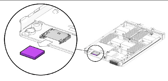
The compact flash (CF) card slot is located on the rear panel of the server. To install or remove the CF card, you must power off the server and remove it from the chassis. For CF card removal instructions, see Removing the Compact Flash Card.
|
1. Set the server module on a flat surface.
2. Orient the server so that the CF card slot is positioned as shown in FIGURE 1-1.
You can access the CF card from the rear of the server module without removing the server’s cover. If necessary, remove the top cover.
FIGURE 1-1 Installing the Compact Flash Card

3. Insert the CF card into the card slot as shown in FIGURE 1-1.
Push the card until it seats and locks into place.
This section describes the hardware installation of the Sun Blade X6440 server module in a chassis. To perform this procedure you must have already completed the installation of the chassis.
| Note - It is not necessary to power off the chassis to install the Sun Blade X6440 server module. |
|
1. Locate an available slot in the chassis for the Sun Blade X6440 server module.
2. Make note of the chassis slot or position number.
You will need this number in an upcoming step.
3. If necessary, remove the filler panel.
Pull the filler panel release lever outward to eject the filler panel.

|
Caution - Danger of an unexpected chassis shutdown. Do not operate the chassis with empty slots. Always insert a filler panel into any unused slots to reduce the possibility of chassis shutdown. |
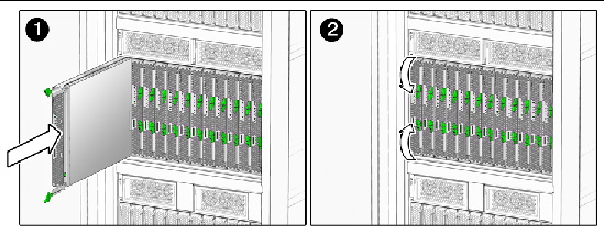
4. Position the server module vertically and orient it so that the ejectors are on the right and extended outwardly (see FIGURE 1-2).
FIGURE 1-2 Inserting the Server Module Into the Chassis

5. Push the server module into the slot until the server module stops.
The module might protrude slightly.
6. Rotate the ejectors levers inward until they are flush with the front of the server module (see FIGURE 1-2).
The inward movement of the ejector levers seats the server module completely in its internal chassis connector. The front of the server module and the ejector lever arms should now be flush with the chassis. Do not power on the server module.
7. Place the server module into standby power mode.
If the chassis was powered on when you inserted the Sun Blade X6440 server module, minimal power is supplied to the server module, and after a few minutes the server module enters standby mode. When the server module is in standby mode, the blue (Ready to Remove) LED is illuminated.
To perform the initial verification and configuration of the SP, you must first place the server in standby power mode. You can place the server module into standby mode by doing one of the following:
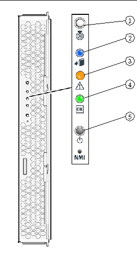
In either of these scenarios, once minimal power is supplied to the server module, it will enter standby mode within a couple of minutes. In standby power mode, the blue (Ready to Remove) LED on the front panel is illuminated, indicating that the SP is working. For the location of the blue front panel LED, see FIGURE 1-3.
Proceed to Connecting to the Server Module ILOM to perform the initial verification and configuration of the SP.
FIGURE 1-3 Sun Blade Server Module Front Panel

When you insert the server module into a chassis that is powered on, minimal power is applied to the server module, placing it in standby mode. When the server module is in standby mode, the blue (Ready to Remove) LED is illuminated.
|
 Press the Power button on the front panel of the server module.
The server module powers on and boots. The green front panel lights solidly.
Before you remove a powered-on Sun Blade X6440 server module from a chassis, you should take it from a fully operational state and place it into standby mode.
|
 Press and hold the Power button until the blue (Ready to Remove) is illuminated.
The server is now in standby mode, and you can remove it from the chassis.
Your Sun Blade X6440 server module does not contain hard drives. Therefore, you must configure your server module’s system BIOS to boot from an external drive. Your Sun Blade X6440 server module is equipped with a compact flash (CF) card, which you can use to boot a limited number of operating systems and bring the server to an operational state. For more information about booting your Sun Blade X6440 server module, refer to the Sun Blade X6440 Server Module Operating System Installation Guide and the Sun Blade X6440 Server Module Windows Operating System Installation Guide.
The CF card slot is located on the back of the server. To remove the CF card you must first remove the server from the chassis.
| Note - If you remove the CF card, you will not be able to boot the server module. |
|

|
Caution - Danger of an unexpected chassis shutdown. Do not operate the chassis with empty slots. Always insert a filler panel into any unused slots to reduce the possibility of chassis shutdown. |
1. Power off the server (see Powering Off the Server Module).
| Note - It is not necessary to power off the chassis to remove the Sun Blade X6440 server module. |
2. Pull the ejector levers upward, and rotate the levers until they are horizontal.
The action of rotating the levers pulls the server module out of its internal connector, allowing you to easily remove it.
3. Remove the server module by sliding it out from its slot.
4. Set the server module on a flat surface.
5. Insert a filler panel into the vacant slot.
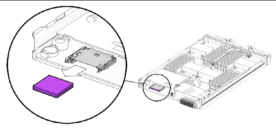
6. Orient the server so that the CF card slot is positioned as shown in FIGURE 1-4.
FIGURE 1-4 Removing the Compact Flash Card

7. Push in on the edge of the CF card.
8. Push the CF card ejector button to release the card from its holder.
This action causes the spring-loaded card to eject.
Copyright © 2009 Sun Microsystems, Inc. All rights reserved.