| Sun Blade X6440 Server Module Service Manual |
| C H A P T E R 2 |
|
Powering On and Configuring BIOS Settings |
You can power on the Sun Blade X6440 server module directly from the front panel. You can power off the server module using one of four different methods. In addition, you can configure or change serveral BIOS settings.
The following topics are contained in this chapter:
| Note - Before powering on your server for the first time, follow the installation instructions provided in the Sun Blade X6440 Server Module Installation Guide
(820-3961). |
1. Verify that power cords have been connected to the chassis power supplies and that standby power is on.
Approximately 1 to 2 minutes after initial power is supplied, the service processor will boot and the blue (Ready to Remove) LED on the server module front panel illuminates, indicating that the server module is ready to be fully powered on to main power mode. See FIGURE 2-1 for the LED location.
2. Use a stylus, or other pointed object, to press and release the recessed Power button on the front panel of the server.
See FIGURE 2-1 for the Power button location.
When main power is applied to all components in the server, the Power LED next to the Power button lights and remains lit.
FIGURE 2-1 shows the location of the Power button.
FIGURE 2-1 Power Button and Power LED Location

1. Choose a method for shutting down the server from main power mode to standby power mode.
a. Select Remote Control => Remote Power Control.
The Server Power Control page appears.
b. Select an action from the drop-down list.
Refer to the Sun Integrated Lights Out Manager 2.0 User’s Guide (820-1188) for more information.
When the main power is off, the blue (Ready to Remove) LED on the server module front panel illuminates, indicating that the server is in standby power mode.
2. To completely power off the server, remove the server module from the chassis.
See Removing the Server Module From the Chassis and Removing the Cover.
This section describes how to view and modify the BIOS settings.
The Basic Input/Output System (BIOS) has a setup utility stored in the BIOS flash memory. The setup utility reports system information and can be used to configure the BIOS settings. The configured data is provided with context-sensitive help and is stored in the system's battery-backed CMOS RAM. If the configuration stored in the CMOS RAM is invalid, the BIOS settings default to optimal values specified in the BIOS.
The BIOS Setup Utility contains seven menu screens, which are displayed in this order: Main, Advanced, PCI/PnP, Boot, Security, Chipset, and Exit.
Use the left and right arrow keys to move sequentially back and forth through the seven screens. Fields that can be reconfigured are displayed in color. All other fields are nonconfigurable. Use the up and down arrows, on the keyboard, to scroll through a screen's menu. Use the Tab key to move back and forth across columns.
You can change the BIOS configuration using several different interfaces:
1. To change the system parameters, enter the BIOS Setup Utility by pressing the F2 key while the system is performing the power-on self-test (POST).
POST testing is indicated when the Power LED on the server module front panel goes into slow-blink mode.
2. Highlight the field to be modified using the arrow and Tab keys.
3. Press Enter to select the field.
A dialog box appears. The box presents you with the options available for the setup field that you have chosen.
4. Modify the setup field and close the screen.
5. If you need to modify other setup parameters, use the arrow and Tab keys to navigate to the desired screen and menu item, and then repeat Steps 1 through 3. Otherwise, go to Step 6.
6. Press and release the right arrow key until the Exit menu screen is displayed.
7. Follow the instructions on the Exit menu screen to save your changes and exit the Setup Utility.
This section contains information and considerations regarding the system BIOS.
The Sun Blade X6440 server module has up to two PCI ExpressModules (PCI EMs) per server module installed in the chassis.
The slots for the PCI Express Modules are detected by the BIOS during startup in this order: PCI EM BLx.1 and PCI EM BLx.0. For example, if the server module is in slot 3, the BIOS boot priority is 3.0, 3.1.
See the chassis documentation for further information on PCI EMs.
The Sun Blade X6440 server modules have up to two 10/100/1000BASE-T Gigabit Ethernet ports provided by the network express module (NEMs) installed in the chassis. The lower NEM port is NET 0 and the upper NEM port is NET 1, as shown in FIGURE 2-2.
If you have the Infiniband NEM installed, only one Ethernet port per server module will be available.
FIGURE 2-2 Ethernet Port Chassis Labeling Designations

See the chassis documentation for further information on NEMs.
The device naming for the Gigabit Ethernet NEM Ethernet interfaces is reported differently by different interfaces and operating systems. Refer to FIGURE 2-3 for a diagram that explains how various operating systems and interfaces name the two Ethernet ports shown in FIGURE 2-2.
| Note - If you have an Infiniband NEM, the Net 0 interfaces only are used. |
FIGURE 2-3 Sun Blade X6440 Server Module Gigabit Ethernet NEM Port Naming

The order in which the BIOS detects the Gigabit Ethernet NEM ports during bootup, and the corresponding drivers that control those ports, are listed below:
The BIOS Option ROM is 128 kbytes. Of these 128 kbytes, approximately 80 kbytes are used by the VGA controller, the LSI controller, and the network interface card. Approximately 48 kbytes remain for the Option ROM.
TABLE 2-1 contains summary descriptions of the seven top-level BIOS setup screens and indicates the section that contains examples of the BIOS screens.
FIGURE 2-4 summarizes the BIOS Configuration Utility menu tree. See the following sections for examples of each of these screens.
FIGURE 2-4 Sun Blade X6440 Server Module BIOS Configuration Utility Menu Tree
The following figures show sample BIOS setup menu screens and show optional default settings.
| Note - The screens shown are examples. The version numbers and the screen items and selections shown are subject to change over the life of the product. |
The following sections show how to modify system settings using jumpers on the server motherboard:
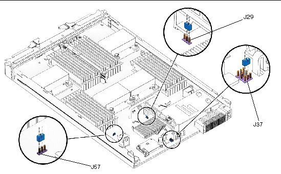
FIGURE 2-5 shows the header pin locations on the Sun Blade X6440 server module that are referenced in the following procedures.
FIGURE 2-5 Header Pin Locations
You can use this jumper to clear the server’s CMOS settings in the case of a system hang. For example, if the server hangs because of incorrect settings and does not boot, use this jumper to invalidate the settings and reboot with defaults.
1. Shut down the server to standby power mode. Use a stylus, or other pointed object, to press and release the recessed Power button on the server module front panel.
2. Remove the server module from the chassis.
See Removing the Server Module From the Chassis
3. Remove the main cover from the server.
4. Install the shorting jumper across the J29 header pins.
See FIGURE 2-5 for the header pin location.
5. Wait 10 seconds, and then remove the shorting jumper.
This jumper removes battery power from the SouthBridge chipset, where the CMOS settings are stored, thereby removing the CMOS settings.
6. Reinstall the main cover to the server.
7. Reinstall the server module into the server.
See Removing the Server Module From the Chassis. The server powers up to standby power mode, indicated when the blue (Read to Remove) LED on the server module front panel is illuminated.
8. Return the server to main power mode. Use a stylus, or other pointed object, to press and release the recessed Power button on the server module front panel.
This procedure describes how to reset the Administrator password (the root password) for the ILOM service processor (SP) back to the default after it has been set once during initial setup.
1. Shut down the server to standby power mode. Use a stylus, or other pointed object, to press and release the recessed Power button on the server module front panel.
2. Remove the server module from the chassis.
See Removing the Server Module From the Chassis.
3. Remove the main cover from the server.
4. Install the shorting jumper across the J37 header pins.
See FIGURE 2-5 for the header pin location.
This jumper’s function is to clear the ILOM SP password.
5. Reinstall the main cover to the server.
6. Reinstall the server module into the chassis.
See Removing the Server Module From the Chassis. The server powers up to standby power mode, indicated when the blue (Read to Remove) LED on the server module front panel is illuminated.
7. Return the server to main power mode. Use a stylus, or other pointed object, to press and release the recessed Power button on the server module front panel.
8. Log in to the ILOM web GUI using root as the user name and changeme as the password.
Refer to the Sun Integrated Lights Out Manager 2.0 User’s Guide (820-1188).
9. Change the default password to a password of your choice.
10. Repeat Steps 1 through 7 to remove the J37 jumper. (Remove the jumper in Step 4 rather than inserting it.)
| Note - If you do not remove this jumper, the ILOM SP password will be reset every time you power cycle the server. |
You may need to recover the service processor (SP) if it hangs due to an incomplete flash. Use this jumper to hold the SP in reset.
The procedures in this section require you to use:
1. Load the Tools & Drivers DVD into a DVD-ROM drive.
2. Navigate to the /SPrecovery directory and copy the following files to a bootable USB flash drive.
3. Shut down the server to standby power mode. Use a stylus, or other pointed object, to press and release the recessed Power button on the server module front panel.
4. Remove the server module from the chassis.
See Removing the Server Module From the Chassis
5. Remove the main cover from the server.
6. Install the shorting jumper across the J57 header pins.
See FIGURE 2-5 for the header pin location.
7. Reinstall the main cover to the server.
8. Reinstall the server module into the server.
See Removing the Server Module From the Chassis. The server powers up to standby power mode, indicated when the blue (Read to Remove) LED on the server module front panel is illuminated.
9. Attach a dongle cable to the server module universal connection port (UCP).
See FIGURE 1-2 for information on the dongle cable connection.
10. Insert the bootable USB flash drive into a dongle cable USB connector.
11. Return the server to main power mode. Use a stylus, or other pointed object, to press and release the recessed Power button on the server module front panel.
During system boot, you will receive a BMC not responding message:
12. When you receive this message, press F8.
13. Select the USB flash drive as the boot device and click Enter to continue.
The system will finish booting from the USB flash drive.
14. Open a terminal window and type the following command to reflash the server module SP:
The server module SP firmware is reflashed.
15. Repeat Steps 3 through 8 to remove the J57 header pins jumper. (Remove the jumper in Step 6 rather than inserting it.)
The BIOS is updated whenever you update the ILOM service processor firmware. For instructions on updating the firmware, refer to the Sun Integrated Lights Out Manager 2.0 User’s Guide (820-1188).
For information about BIOS POST, POST codes, POST code checkpoints, and console redirection, see Appendix B.
| Sun Blade X6440 Server Module Service Manual | 820-3964-10 |
Copyright © 2009 Sun Microsystems, Inc. All rights reserved.