Chapter 7 Creating a Centralized Management Group
Typically, you use centralized management (CMG) to simultaneously administer configurations on a group of Screens. A CMG contains a primary Screen and some number of secondary Screens. Besides its firewall function, the primary Screen's main purpose is to push policy configurations to all of the secondary Screens in the CMG.
Note -
Only a full function (non-Lite) routing-mode Screen can be a CMG primary. However, you can configure both stealth and routing-mode Screens as CMG secondaries.
Network Example
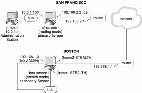
Figure 7-1 shows the San Francisco and Boston segments of the network. In this diagram, sf-screen1 is the primary routing-mode CMG Screen and bos-screen1 is the secondary CMG Screen (running in stealth mode.) You can add additional secondary CMG Screens by following this same procedure.
Figure 7-1 San Francisco and Boston Segments of the Sample Company Network

Centralized Management Group Configuration
Install SunScreen on the Primary and Secondary Systems
-
On the CMG primary system, install the Screen software in routing mode with remote Administration Station .
See Chapter 2, Setting Up Remote Administration in Routing Mode for installation information.
In this example, the primary Screen is called sf-screen1 and the Administration Station is named sf-host4. Be sure to write down the Screen's certificate ID for use in the next step. Refer to "Setting Up Remote Administration with SKIP" for instructions on this step.
-
On the CMG secondary system, install the Screen software in stealth mode.
See " Stealth Mode Configuration" for installation information.
In this example, the secondary Screen is called bos-screen1. Use the certificate generated in the previous step when prompted for the Administration Station's certificate ID. This certificate is given the name "remote" by default.
Configure the CMG Secondary Screen
In this example the CMG secondary Screen is named bos-screen1.
-
Configure the stealth mode Screen bos-screen1 as a secondary Screen in the centralized management group.
Create the following objects to enable Screen sf-screen1 to push the security policy to bos-screen1.
-
Create address objects (to enable definition of the stealth interfaces), screen objects, and policy rules shown in the following table.
Table 7-1 Address Object DefinitionsName
Type
Address
sf-screen1
Host
192.168.1.2
bos-screen1
Host
10.0.2.200
bos-ext-router
Host
192.168.2.1
bos-net-10
Range
10.0.2.0 - 10.0.2.255
bos-net-192
Range
192.168.2.0 - 192.168.2.255
bos-internal
Group
Include: bos-net-10, bos-net-192
Exclude: bos-ext-router, *
bos-external
Group
Include: *, bos-ext-router
Exclude: bos-net-10, bos-net-192
-
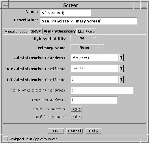
Create a screen object for primary Screen containing the administrative IP Address and certificate under the Primary/Secondary Config Tab, shown in Figure 7-2.
This secondary screen expects packets to originate from that Administrative IP address when the primary screen is in control. If the primary screen has more than 1 interface then activation may fail because the packets came from the wrong IP address. The Administrative IP address must be an address object in the Registry. It can also be a group object containing more than 1 IP address or *which means any address.
The Administration Certificate is the primary Screen's certificate. This could be any valid certificate on the primary Screen. You can create this certificate as part of the installation process or use this alternative method: Create a certificate object for the primary on the secondary using Associate MKID and give it a name like sf-screen1.admin. Then, make this certificate the Administration Certificate in the primary screen object.
Figure 7-2 Screen Object for sf-screen1

-
Create interface objects like the ones shown in the following table.
Table 7-2 Interface Object DefinitionsName
Screen
Type
Address Group
qfe0
bos-screen1
STEALTH
bos-external
qfe1
bos-screen1
STEALTH
bos-internal
hme0
bos-screen1
ADMIN
bos-screen1_hme0 (created by default)
-
-
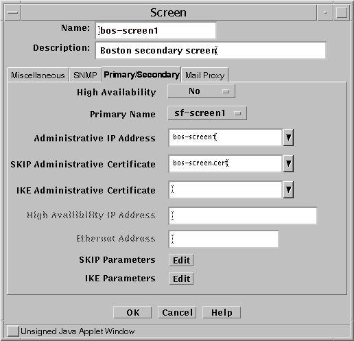
Modify the Screen object and select the primary Screen as the Primary Name. Be sure you specify the correct the Administrative IP Address and Administrative Certificate, as shown in the following figure.
Figure 7-3 Screen Object for bos-screen1

-
Create policy rules to enable SunScreen SKIP and CDP packets from the primary screen to pass through the Screen shown in the following figure.
Figure 7-4 Policy Rules to Allow SunScreen SKIP and CDP Packet Flow

-
Save and activate the policy on bos-screen1.
Configure the CMG Primary Screen
-
On the primary Screen, create the objects needed to push the policy to secondary Screen
In this example, you would create the following objects:
-
These Address objects are needed for the example configuration.
Table 7-3 Address Objects To Enable ConfigurationName
Type
Address
sf-screen1
Host
192.168.1.2
bos-screen1
Host
10.0.2.200
bos-ext-router
Host
192.168.2.1
bos-net-10
Range
10.0.2.0 - 10.0.2.255
bos-net-192
Range
192.168.2.0 - 192.168.2.255
bos-internal
Group
Include: bos-net-10, bos-net-192Exclude: bos-ext-router, *
bos-external
Group
Include: *, bos-ext-routerExclude: bos-net-10, bos-net-192
-
Create a Certificate object called bos-screen1.admin using the Associate MKID selection by choosing Certificate and then Add New in the Policy Objects area. Use the certificate ID that was generated previously.
-
Create a Screen object for bos-screen1 containing sf-screen1 as the primary Name, bos-admin1 as the Administrative IP Address, and bos-screen1.admin as the Administrative Certificate.
This looks the same as it did on the secondary Screen, as shown in Figure 7-3.
-
Create Interface objects as shown in the following table:
Table 7-4 Interface Objects for bos-screen1Name
Screen
Type
Address Group
qfe0
bos-screen1
STEALTH
bos-external
qfe1
bos-screen1
STEALTH
bos-internal
hme0
bos-screen1
ADMIN
bos-screen1_hme0 (created by default)
Be sure that all interface definitions for the primary Screen contain sf-screen1 in the Screen field.
-
-
Add policy rules to enable SunScreen SKIP and CDP packets from sf-screen1 to pass through Screen bos-screen1, as shown in Figure 7-4 .
Be sure that each rule has an entry in the Screen object field to tell it which Screen is to implement the particular rule.
-
Save and activate the policy on sf-screen1.
Your centralized management group is now configured, and is ready for you to implement your full security policy.
In the network diagram, Figure 7-1, the primary routing-mode Screen sf-screen1 is shown in an HA cluster configuration. You can configure your primary, centrally managed Screen with HA if you desire. However, you should first follow the steps to get your centralized management group working, then follow the procedure for adding the secondary HA Screen into the configuration.
- © 2010, Oracle Corporation and/or its affiliates
