Chapter 8 Using Proxies in Mixed-Mode
This configuration example shows how to use proxies in mixed-mode. In mixed-mode, one interface on the Screen is configured as in stealth-mode and the others are configured in routing-mode. You are not required to use mixed-mode in order to use proxies; you can also use proxies on a Screen in routing mode.
Typically, you use SunScreen in a mixed-mode configuration to provide the advantages of stealth to the subnet it partitions without the additional cost of a second Screen. The subnet is not visible outside of the network and can be added to a network without changing IP addresses.
Network Example
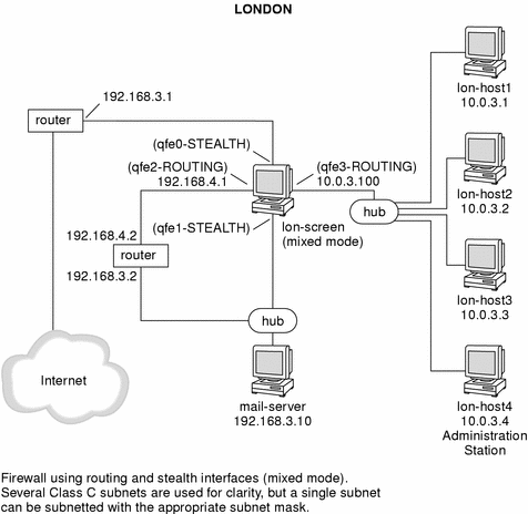
Figure 8-1 shows the London segment of the network example. In this diagram, a mixed-mode Screen, (lon-screen1) provides stealth protection on interfaces facing the internet and routing interfaces on the internal network. The stealth interfaces give the DMZ stealth protection for the mail server and the routing interfaces enable proxy user authentication to the internal network. The routing interfaces also allow internal access to the mail server and also internet access.
In this configuration, the hosts protected by the Screen have illegal IP addresses that give them web access to the Internet. The Screen also acts as an HTTP proxy and performs NAT for these hosts as well.
Note -
Use care when designing the security policy for the routing interfaces. An open policy on a routing interface (like qfe2 in this example), can expose the Screen to attacks, and can affect the stealth operation as well as negate the advantage of the stealth interface.
Figure 8-1 London Segment of the Sample Company Network
Configuration Considerations
The following parameters are used to implement this example:
-
Two interfaces are set up in stealth mode
-
Two interfaces are set up in routing mode
Note -The routing and stealth interfaces must be on different subnets, and separated by an external router.
-
User authentication is provided for telnet access from the Internet to the internal network (lon-host1, and so forth)
-
Anonymous FTP access is provided using the FTP proxy to lon-host2 (ftp-server)
-
Rules are added to only ALLOW SMTP access to mail-server
-
Rules are added to only ALLOW authenticated telnet and FTP to the qfe2 interface of lon-screen1
-
The HTTP proxy is used to provide web access to the Internet
All proxies are accessed through the transmission control protocol (TCP), and therefore can only run on systems configured in routing mode.
Mixed-Mode Limitation
Because NAT has a single state table only, NAT cannot be used to translate the IP addresses of the internal network in this mixed-mode configuration. You can, however, use NAT on the routing interfaces and on the stealth interfaces on a mixed-mode Screen provided that the packets only pass through the Screen once.
NAT is not required because the proxies that provide the telnet/ FTP/HTTP connections between the Internet and the internal network use the IP address of the Screen and not the illegal IP address of the host. Therefore, only the Screen needs to be able to resolve the host's IP address.
For example, the mail-server can have its address translated when packets pass to the Internet because the packets only pass through the stealth interfaces once. This is true of any host on the private part of the network (192.168.3.0 in this example) or on the 192.156.4.0 network.
Using DYNAMIC NAT
The following steps outline how DYNAMIC NAT is used to translate the source IP addresses of hosts on the network (10.0.3.0 in this example) to a legal address (192.168.3.100 in this example).
-
Add rules to ALLOW hosts on the 10.0.3.0 network free access to the Internet.
-
Add rules to only ALLOW SMTP access to mail-server.
-
Add rules to only ALLOW authenticated telnet and FTP to the qfe3 interface of lon-screen1.
Note -The routing and stealth interfaces must be on different subnets, and separated by an external router.
Mixed-Mode Configuration
Performing Preliminary Steps
The following steps illustrate what you would have to do to create a network like the one in the example. Your own configuration may differ significantly but the general steps would still apply.
-
Configure the routing interfaces with the correct IP addresses.
In this example, the routing interfaces are named qfe2 and qfe3
-
Confirm that the Screen can contact the addresses of both the internal router and the internal hosts.
Make sure to use the correct routing and netmasks.
-
Install the Screen in routing-mode with remote administration.
Use the steps described previously in "Setting Up Remote Administration with SKIP" Select "routing mode" when installing the firewall software even though this Screen has both stealth- and routing-mode interfaces. In this example, lon-host4 is the remote Administration Station.
-
After rebooting the Screen, start a browser on the Administration Station and log into the Screen.
-
Define the Address objects that reflect the topology of your network.
For this example, you would create the Address objects shown in the following table
Table 8-1 Address ObjectsName
Type
Details
external-router
HOST
192.168.3.1
168.3-private
RANGE
192.168.3.2 to 192.168.3.254
mail-server
HOST
192.168.3.10
168.4-net
RANGE
192.168.4.1 to 192.168.4.254
10.0.3-net
RANGE
10.0.3.1 to 10.0.3.254
ftp-server
HOST
10.0.3.3
qfe3_grp
GROUP
Include {10.0.3-net}
Exclude {}
qfe2_grp
GROUP
Include {*}
Exclude {10.0.3-net}
qfe1_grp
GROUP
Include {168.3-private 168.4-net 10.0.3-net}
Exclude {}
Internet
GROUP
Include {*}
Exclude {qfe1_grp}
qfe0_grp
GROUP
Include {Internet}
Exclude {}
Note -The address groups (for example, qfe1_grp) must contain all the IP addresses that can be reached from that interface.
-
Verify that the routing interfaces were defined by the installation procedure.
In this example, the routing interfaces are qfe2 and qfe3. They must have the interface groups qfe2_grp and qfe3_grp assigned to them, respectively.
-
Add INTERFACE objects for the stealth interfaces.
In this example, you would define qfe0 and qfe1 as using the address groups qfe0_grp and qfe1_grp. These interfaces must be defined as TYPE: STEALTH.
-
Edit the Screen object ensuring that the STEALTH SUBNET/NETMASK are defined.
In this example, the values would be 129.168.3.0 and 255.255.255.0.
-
Install an open, or a test, policy.
-
Save and activate the policy.
-
Verify that the configuration works.
In this example, you would try to ping the mail-server from an external host.
Verify that this host can ping the Screen's external routing interface qfe2.
Configuring Proxies for User Authentication
In Figure 8-1, telnet access is required to the hosts on the 10.0.3.0 network from unspecified hosts on the Internet. To give access to your trusted users only, implement user authentication.
Set Up Telnet User Authentication
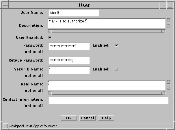
This example shows six user names that need access to the 10.0.3.0 network: Mathew, Mark, Luke, and John.
-
Define each of your users as an Authenticated User, as shown in the following figure:
Figure 8-2 Authenticated User Definition
-
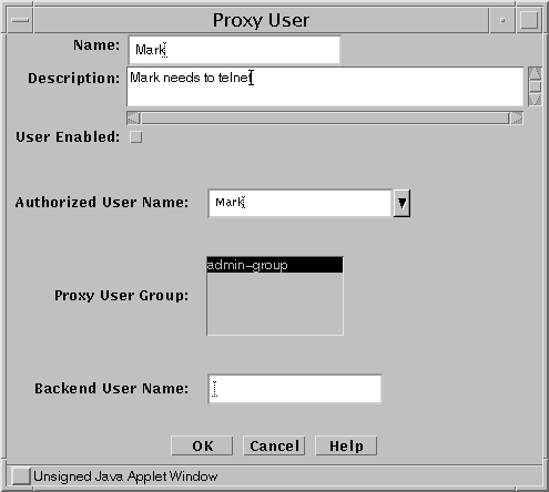
Define each of your users as a Proxy User, as shown in Figure 8-3.
Define only those users who are qualified to use the proxy for authentication.
Figure 8-3 Proxy User Definition
-
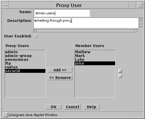
Create a rule to ALLOW proxy access that references either a single Proxy User, or, more usually, a GROUP of Proxy Users, as shown in the following figure.
Figure 8-4 Proxy User Name Used in the Rule
-
Define a Proxy User GROUP with all your users.
-
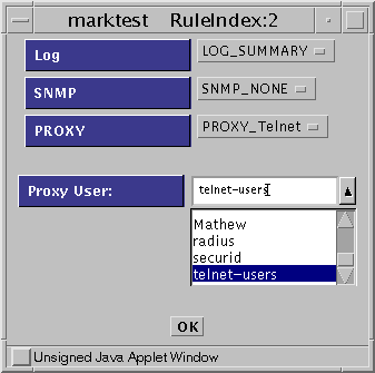
Add a rule to ALLOW telnet with Proxy AUTHENTICATION, as shown in the following figure.
Figure 8-5 ALLOW telnet Rule
-
Save and activate the configuration.
Set Up FTP Authentication
Another requirement is to ALLOW anonymous FTP to the server lon-host3 using the FTP Proxy. Because this is anonymous FTP, you do not have to create an Authenticated User. Use the predefined Proxy Users for ftp and anonymous for this purpose.
The advantage of using the FTP Proxy to ALLOW anonymous FTP access over a regular packet filter rule in this configuration is that the outside world does not need to know which system is the FTP server. Because the FTP connection is made from the firewall, only the firewall needs to know how to resolve the name ftp-server to an IP address. The firewall can use a simple alias in its hosts file and can be changed to another server without having to tell your users. In this example, the FTP server lon-host3 has an illegal IP address, which is enabled because the firewall can contact it.
Note -
Using NAT with a conventional packet filtering rule requires you to add a DNS entry for this host.
-
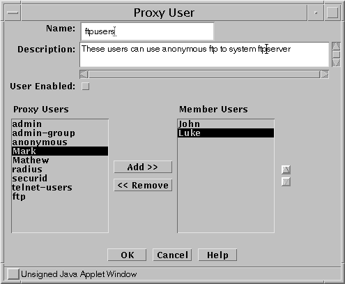
Define a Proxy User Group that contains the users who can use FTP, as shown in the following figure.
Figure 8-6 Proxy User Group Definition
-
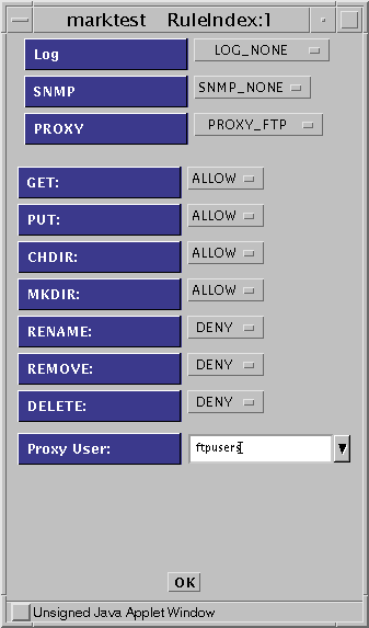
Define a rule to ALLOW FTP access, as shown in the following figure.
Figure 8-7 ALLOW FTP Access Rule Definition
-
Save and activate the policy.
Set Up HTTP the Proxy
Because the users behind the firewall have illegal IP addresses and NAT cannot be used in a mixed-mode configuration, the HTTP proxy can be used to provide Internet access for your internal users.
-
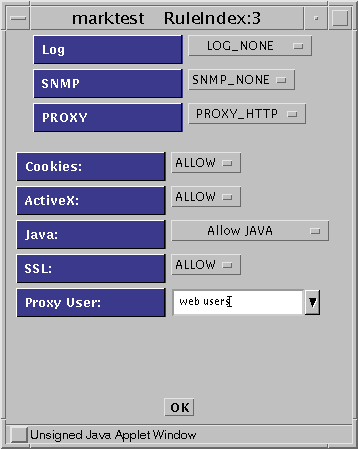
Add a rule to ALLOW Internet access, as shown in the following figure.
Figure 8-8 Rule Definition: Initial Window
-
Save and activate the policy.
The internal hosts must set the Proxy Address of their browsers to the internal IP address of the firewall (10.0.3.100 in this example).
Proxy Considerations
Ensure that the rules do not open a back door into the Intranet that bypasses the proxy rules (for example, a rule that enables telnet directly to a host).
Adding a rule that explicitly drops telnet/FTP after the proxy rules does this as shown in Figure 8-9.
Figure 8-9 Add a Rule to Drop telnet or FTP After the Proxy Rules
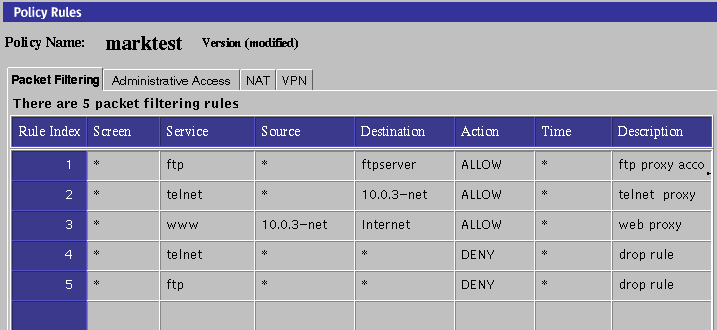
Your user must telnet/ FTP to the firewall to be authenticated. The proxy connects the user to the target system (even though the rule has the destination address as the target host).
After configuring a proxy rule, you may need to reboot or rule this script to start the proxy by typing:
# /etc/rc2.d/S79proxy start |
You can verify that the proxies are running by typing:
# ps -ef |
which gives results like those shown in the following table:
Table 8-2 Proxies|
root 4820 |
1 0 15:25:47? |
0:00 /opt/SUNWicg/SunScreen/proxies/ftpp |
|
root 4819 |
1 0 15:25:47? |
0:00 /opt/SUNWicg/SunScreen/proxies/telnetp |
|
root 4818 |
1 0 15:25:47? |
0:00 /opt/SUNWicg/SunScreen/proxies/httpp |
The common objects, authorized user, administrative user, and proxy user that appear in the administration GUI are automatically saved when they are edited or new objects are added. You do not need to save these objects. Changes made to them apply immediately and cannot be reversed; however, they do not take effect until a policy is activated. To install the new objects and to propagate these changes to secondary Screens, activate your system configuration.
Note -
The Save button is grayed out to show that it is inactive.
See the SunScreen 3.2 Administrators Overview for more information regarding authentication.
- © 2010, Oracle Corporation and/or its affiliates
