Chapter 1 Preparing for SCI Installation
This chapter describes the SCI network configurations that are supported by Sun HPC ClusterTools 3.0 software suite.
Other Necessary Documentation
The hardware installation and service manuals provided with your Sun server are likely to contain important information about installing SCI adapter cards and network cables. Please read the applicable sections of the Sun server hardware manuals before installing and configuring an SCI network on your Sun HPC cluster.
SCI Adapter Cards
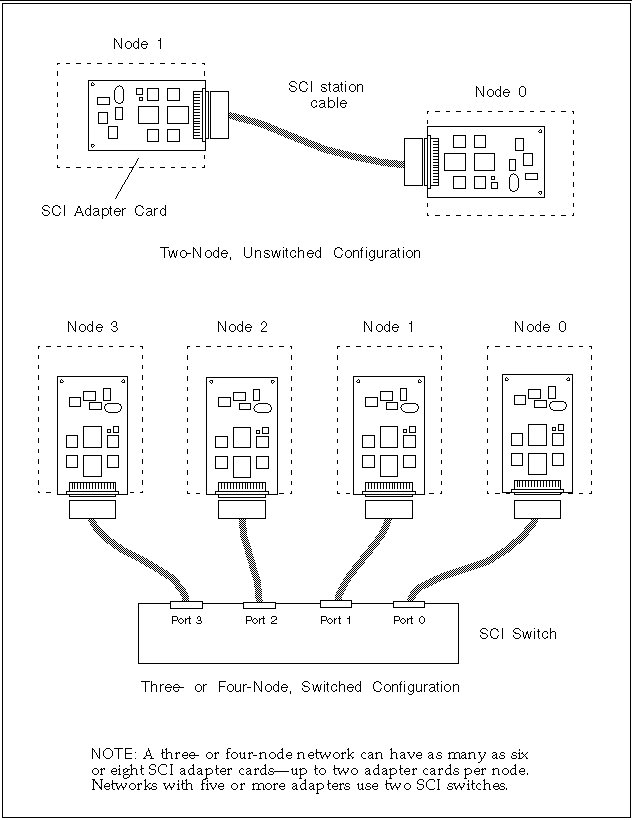
Sun HPC 3.0 cluster nodes connect to the SCI network through SCI adapter cards installed in the node's SBus slots. In two-node SCI networks, the SCI adapter cards are ordinarily connected to each other directly, without going through a switch. One possible exception to this switchless approach is discussed in "Connecting SCI Adapter Cards in a Two-Node Network".
In three- and four-node networks, each adapter card is connected to a port in a four-port SCI switch. These two basic SCI network connections schemes are shown in Figure 1-1.
Figure 1-1 Basic SCI Network Connection Schemes for Sun HPC 3.0 Clusters
Supported SCI Network Topologies
A Sun HPC 3.0 cluster can have up to four nodes connected to an SCI-based private subnet. The nodes may connect to the SCI network through one or two SCI adapter cards. When each node in the network has two SCI adapter cards, communication bandwidth can be increased by striping messages across both network interfaces.
Note -
See the Sun HPC ClusterTools 3.0 Adminstrator's Guide: With LSF or Sun HPC ClusterTools 3.0 Adminstrator's Guide: With CRE for additional information about configuring a Sun HPC cluster to support message striping.
Chapter 2, Network Connection Procedure describes the procedure for connecting the nodes in the various network topologies described below. Chapter 3, Configuring the SCI Network Interface describes the procedure for configuring the SCI drivers.
Two-Node Networks
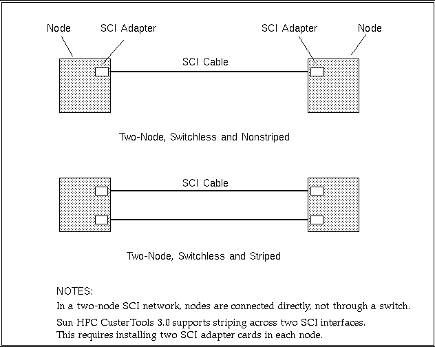
Figure 1-2 shows how two nodes in a Sun HPC 3.0 cluster can be connected via an SCI network. The SCI adapter card in one node is connected directly to an SCI adapter card in the other node. There is no intervening SCI switch, which is the usual connection scheme for two-node networks.
If each node has two SCI adapter cards, messages can be striped across the two network interfaces. This is illustrated in lower schematic in "Connecting SCI Adapter Cards in a Two-Node Network".
Figure 1-2 Two-Node SCI Interconnection, Without Striping
If you expect to add a node to a two-node network at a later time, you may want to connect the two nodes through a switch now, even though the switch is not needed. This would simplify the process of adding a third node later on. The chief disadvantage to using a switch in a two-node network is the latency it adds to the communication path between the nodes.
This alternate connection scheme is discussed further in "Connecting SCI Adapter Cards in a Two-Node Network".
Three-Node Networks
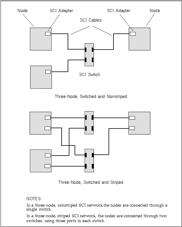
Figure 1-3 shows examples of how three Sun HPC nodes can be connected to an SCI network, in both unstriped and striped modes.
Figure 1-3 Supported Three-Node SCI Interconnections
Four-Node Networks
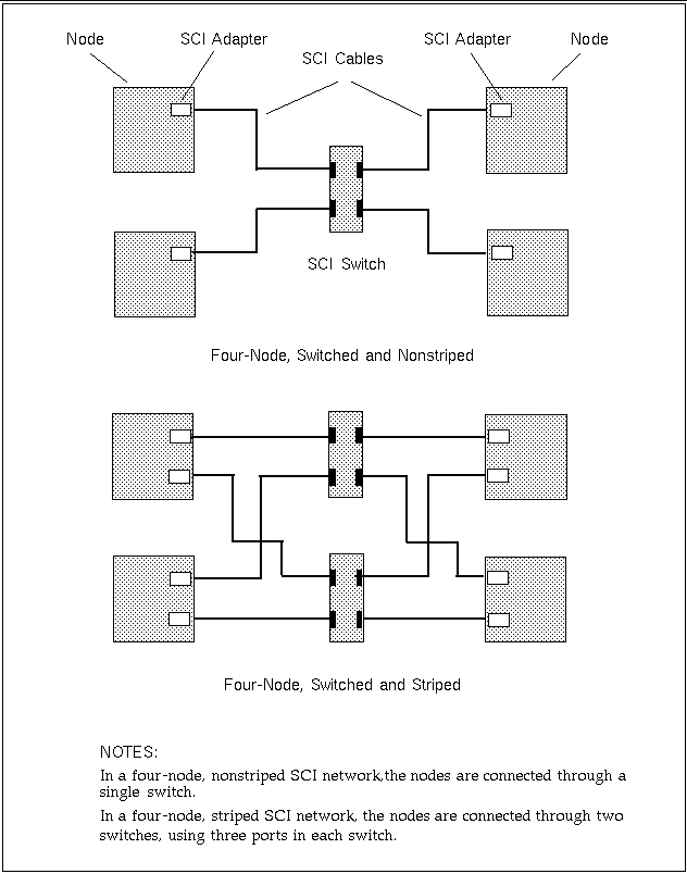
Figure 1-4 shows examples of how four Sun HPC nodes can be connected to an SCI networ, in both unstriped and striped modes.
Figure 1-4 Supported Four-Node SCI Interconnections.
SCI Adapter Card Scrubber Jumpers
Each SCI adapter card has a jumper, called the scrubber jumper. This jumper configures the scrubber circuit, which controls link maintenance functions. Figure 1-5 shows its location on the SCI adapter card.
Figure 1-5 Location of the Scrubber Jumper
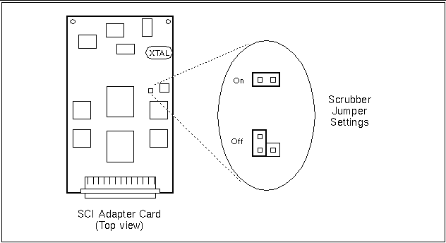
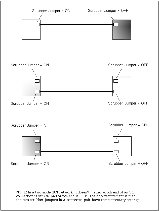
Table 1-1 specifies the appropriate scrubber jumper settings for unswitched and switched SCI networks.
Table 1-1 Scrubber Jumper Settings|
Topology |
SCI SBus Card Jumper Settings |
|---|---|
|
Two nodes (unswitched) |
Set one jumper ON and the other jumper OFF in each connected pair of SCI adapter cards. See Figure 1-6 for examples of two-node jumper settings. |
|
Three or four nodes (switched) |
Set all jumpers ON. |
Figure 1-6 Examples of Scrubber Jumper Settings in Two-Node Networks
Note -
SCI adapter cards are shipped without a default setting. Therefore, examine the setting on each SCI adapter card and adjust it if necessary. If scrubber jumpers are not set correctly when installed, communication between nodes may experience intermittent faults.
- © 2010, Oracle Corporation and/or its affiliates
