Chapter 6 Configuring Solstice X.25 Services
This chapter explains how to set up some of the basic configurations listed under Services in the x25tool menu. For additional configurations, see Chapter 8, Example Configurations.
Configuring Solstice X.25 to Route IP
The TCP/IP protocol suite is the de facto standard for networking. IP can be run above X.25, creating a Wide Area Network using TCP/IP. This allows for the use of rlogin, ftp and other useful facilities. The TCP/IP protocol suite is delivered as part of the Solaris system software.
To route IP over Solstice X.25, you must set up a mapping between the X.121 addresses used by the X.25 software and the IP addresses used by the IP software. The IP over X.25 Configuration window contains many parameters, but you only need to use a few of them. You can configure information about your local system, mapping its X.121 address to an IP address and setting any necessary parameters, and also information about remote systems.
To access the IP Interface Configuration window, pull down the Services menu and choose IP => IP Interface:
Figure 6-1 Setting the Local IP Address and IP Subnet Mask
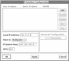
First, configure information about your local system. To do so:
-
Click on the Add button.
-
Enter the Local IP address of the interface you are configuring.
Enter either an address in IP dotted notation, or a hostname.
-
Select either Point-to-Point, or Point-to-Multipoint.
-
Enter the Remote IP Address for a Point to Point configuration, or enter the IP Subnet Mask for a Point to Multipoint configuration.
-
Click on the Apply button.
-
Select the Local Address, and click on the Modify button.
You must do this before you can access the X.25 Parameters window.
-
Select X.25 Parameters and configure any other relevant parameters.
See "IP Interface Configuration" for information about the available parameters.
-
Click on OK to apply the changes and to exit the X.25 Parameters window.
-
Click on Start to start the IP interface.
-
Click on OK to apply the changes and to exit the IP Interface window.
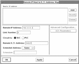
You also need to add information about remote hosts to the IP Mapping window. This lets the Solstice X.25 software translate the IP addresses it receives into X.25 addresses it can use. To access the IP Mapping window, pull down the Services menu and choose IP => IP Mapping:
Figure 6-2 Adding Information About Remote Hosts in the IP Mapping Window
-
Click on the Add button.
-
Enter the IP Address of the remote system.
-
Specify the link to be used by traffic to this destination (or use 255 for automatic routing).
-
Set the circuit to SVC (switched virtual circuit) or PVC (permanent virtual circuit).
-
Enter the X.25 (X.121) address of the remote system.
-
Click on the Apply button.
-
Select the Remote IP Address, and click on the Modify button.
You must apply the changes before you can access the X.25 Parameters window.
-
Click on the X.25 Parameters button and configure any other relevant parameters.
See "IP Interface Configuration" for information about the available parameters.
-
Click on OK to apply the changes and to exit the X.25 Parameters window.
-
Click on OK to apply the changes and to exit the IP Mapping Window.
Once you have carried out the configuration described above, you should be able to use the TCP/IP protocol suite over your X.25 connection. To check that all is working properly, make sure that you can ping and rlogin to the hosts you added to the IP Host to X.25 Address Map.
Configuring the PAD
Once you have a working connection to a network, you can use it to make PAD calls using the PAD software delivered with the Solstice X.25 software.
Users can make PAD calls without you carrying out any configuration. However in order to do so, they need to know addressing and configuration information for their destination. You can use x25tool to create a database of remote hosts containing relevant addressing and configuration information. This lets users make calls using aliases instead of addresses.
You can also set up a database of parameters to be applied to incoming calls. This is particularly useful if you have a server that receives a large number of calls.
Configuring the PAD Hosts Database
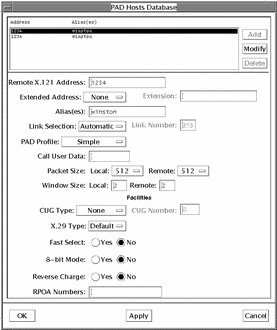
To access the PAD Hosts Database, pull down the Services menu and choose PAD => PAD Hosts Database:
The PAD Hosts Database window looks like this:
Figure 6-3 PAD Hosts Database Window
To add an entry:
-
Click on Add.
-
Specify the X.121 Remote Address.
For a WAN link, this is the DTE address of the remote host. A valid DTE address has 15 or fewer decimal digits.
For a LAN link, this is the LSAP of the remote host. A valid LSAP (MAC plus SAP) address is 14 hexadecimal digits in length. In most cases, the last two digits of an LSAP address are 7e. You can use ARP-style notation, with colons separating the bytes within an LSAP address. Within a colon-delimited byte, you can omit a leading zero.
-
Type the name of the alias you want to use, if appropriate.
-
Add any Aliases you want to use to call this destination.
-
Set the Link Selection parameter to Automatic.
This uses the Solstice X.25 routing link selection feature. In some instances, you may want to specify the link number, instead (a link number of 255 indicates automatic link selection). This allows you to bypass routing specs, or to make certain that the specified link is always used.
-
Change any other relevant parameters.
In most cases you do not need to do this. Refer to "PAD Hosts Database" in Chapter 7, Parameter Reference for information on the other available parameters.
-
Click on OK to add the new entry to the database.
Configuring the PAD Daemon Listen Database
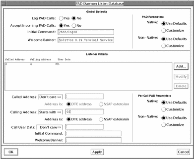
The PAD Daemon Listen Database determines how incoming PAD calls are handled. You can set global default values that are used for all incoming calls and optional values that apply to calls with particular characteristics. To access the PAD Hosts Database, pull down the Services menu and choose PAD => PAD Daemon.
The PAD Daemon Listen Database window looks like this:
Figure 6-4 PAD Daemon Listen Database
-
Configure the PAD Daemon Listen Database to log or not to log PAD calls.
When the Log PAD Calls option is set to Yes, information about each PAD call made is logged to the file /var/opt/SUNWconn/x25/x29serverlog. This file can become very large. If you have problems with disk space, check the x29serverlog file size and, if necessary, delete it.
-
Configure the PAD Daemon Listen Database to accept or not to accept incoming PAD calls.
If the Accept Incoming PAD Calls option is set to No, the system will not accept incoming PAD calls. The system can still make outgoing calls.
-
This is the message that someone logging in to this machine using a PAD call will see when the connection is made. It might be useful to give the machine name or any particular information about this machine that users need.
There are two Welcome Banner fields in the database window. The first is under the Global defaults. The second is displayed under the Listener Criteria. You can specify a Welcome Banner for a particular listener, or you can leave this field blank, in which case the default banner will be used.
If you don't want a Welcome Banner, enter a single space in the field for the global Welcome Banner.
-
This determines what happens when a user connects to this machine using a PAD call. The command /bin/login, which appears by default in this field, prompts for the user's name and password.
There are two Initial Command fields in the database window. The first is under the Global defaults. The second is displayed under the Listener Criteria. You can specify an Initial Command for a particular listener, or you can leave this field blank, in which case the default will be used.
If you don't want an Initial Command, enter a single space in the field for the global Initial Command.
-
Change the Listener Criteria, if necessary.
You can also set the parameters described above so that they are applied differently to certain calls. There are two ways to distinguish which calls they can apply to--using the Called Address and using the Calling Address.
The Called Address is the address of the local machine. If you use sub-addressing, a remote host can call the local machine using any one of these sub-addresses. You can configure the local machine to behave differently depending on the sub-address called--for example, on a machine with several applications, you could use a different sub-address to call each one, using a combination of the Called Address and Initial Command parameters to set this up.
The Calling Address is the address of the machine making the call, the remote machine. Again, you might want to use a different Initial Command, depending on where the call is from. You might also need to use different X.3 parameters if the remote host has a non-default configuration. To set the X.3 parameters, select Customize under PAD Call Parameters. For more information on X.3 parameters, see Chapter 7, Parameter Reference.
To set parameters applying to a particular Called Address, choose Matches and enter the exact address. To apply the parameters to a particular group of Called Addresses, use Starts With to affect all addresses starting in the same way, or Pattern to use wildcards such as an asterisk (*) or a question mark (?).
To set parameters applying to a particular Calling Address, choose Matches and enter the exact address. To apply the parameters to a particular group of Calling Addresses, use Starts With to affect all addresses starting in the same way, or Pattern to use wildcards.
To set parameters applying to calls using specific Call User Data, choose Starts With to affect all calls with CUD starting the same way and Matches to affect all calls using identical CUD. For more information on Call User Data, see Chapter 7, Parameter Reference.
Configuring PAD Printer
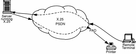
The PAD Printer enables a user who is logged on to a remote terminal to print to the remote user's local printer.
Figure 6-5 shows how the print information is routed through the network to the server running X.25. The print information is then routed back to the local printer through PAD.
Figure 6-5 Using PAD to Print to a Remote User's Local Printer
-
Use admintool to set up the printer.
Do this as you normally would, but make certain that you set it up as a Local Printer, and specify an X.25 printer port that also includes a unique printer number, for example /dev/xtp7. See User Account, Printers and Mail Administration for more information.
-
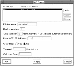
In x25tool, access the PAD Printer window.
Pull down the Services menu and choose PAD => PAD Printer.
Figure 6-6 The PAD Printer Window
-
Click on Add.
-
Type in the printer name.
-
Type in the device number.
This is the printer port number. For example, if you entered /dev/xtp7 for the printer port in admintool, then the device number is 7.
-
Type in the link number.
This is the link to use for the outgoing printer connection. If you set this to 255, the link number will be selected automatically.
-
Type in the remote X.121 address.
This enables X.25 to open a connection. The print information can then be routed from the remote terminal, through PAD, to the local printer.
-
Set Clear Flag to Yes or No.
If set to Yes a Clear Invitation packet is sent at the end of the data transfer, and the connection will then be cleared by the remote PAD after all of the data is received. This ensures that all data have reached the remote PAD, but can lead to the connection staying up if the remote does not support Clear Invitation packet.
If Clear Flag is set to No, then a Clear Invitation packet will not be sent at the end of the data transfer. If the remote PAD does not support Clear Invitation, you should set Clear Flag to No and enter a value for the Timeout.
-
This is the amount of time, in seconds, that the X.25 server will keep the connection open after the last print packet has been sent. Setting a timeout value can help prevent loss of print data, however, you will have to use your own knowledge of the network to determine how long the connection needs to stay open.
You only need to set a timeout if Clear Flag is set to No.
-
Enter the Call User Data.
This is the call user data used to establish the virtual connection. Before this information is included, it should have been agreed upon by both sides of the connection.
-
Click on OK to apply the changes and to exit the PAD Printer window.
NUI Mapping
The Network User Identifier (NUI) parameters are used to create a mapping between Network User Identifiers and facilities. When a call is made using NUI override, the facilities set here override any other facilities that might otherwise apply to the call.
Configuring the NUI Parameters
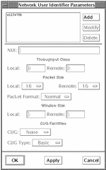
To access the NUI Mapping window, pull down the Services menu and choose Routing. The NUI Mapping window looks like this:
Figure 6-7 Network User Identifier Parameters Window
-
Click on Add.
You can now configure the NUI mapping information.
-
Enter the NUI.
The NUI, the Network User Identifier, is a string of up to 64 alphanumeric characters. The NUI is supplied by your PSDN provider.
-
Enter the Throughput Class information.
This numeric value determines what throughput class is used for incoming (Remote) and outgoing (Local) calls. These can be different.
-
Select the Packet Size.
These are the sizes to use for incoming (Remote) and outgoing (Local) packets. These can be different.
-
Select the Packet Format.
Choose between Normal and Extended.
-
Enter the Window Size.
This is the window size to use for incoming (Remote) and outgoing (Local) calls. These can be different.
-
Select the CUG.
This determines whether Closed User Groups are in use. Choose between None, Normal and Outgoing.
-
Select the CUG Type.
Choose Basic or Extended.
Routing
If you have multiple links, you can control which link X.25 uses by configuring the address information contained in the Routing Parameters window.
Configuring the Routing Parameters
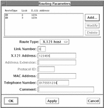
To access the Routing Parameters window, pull down the Services menu and choose Routing. The Routing Parameters window looks like this:
Figure 6-8 Routing Parameters Window
-
Click on Add and select Top from the list displayed.
When you click on Add, you will be prompted to select the position you want the configuration to take in the list. This can be important, since X.25 starts from the top of the list and uses the first set of parameters that match the parameters specified by the application.
-
Select the Route Type.
The default is X.121 Host. This associates the complete X.121 address of a remote host with a link. For a complete description of each of the available route types, see "Routing" in Chapter 7, Parameter Reference.
-
Type in the number of the link you want to associate with the route type.
-
Type in the X.121 host address or prefix.
Type in the complete X.121 address if the routing type is set to X.121 host, AEF host, prefix, or default. If the routing type is X.121 prefix, enter the leading digits (for example, the DNIC) of the X.121 address.
-
For an AEF routing type, enter the address extension.
For an AEF host routing type, enter the complete extended address, such as an OSI NSAP address. For an AEF prefix routing type, enter the leading digits (at least one) of an extended address.
-
Type in the Protocol ID.
Enter the protocol id as a string of consecutive digits no longer than 5 bytes (10 decimal digits). The protocol id is an optional addition to an AEF host, AEF prefix, or AEF default entry.
-
Enter the MAC address to which the call will be routed if the link is a LAN link.
You can include a MAC address with any of the route types.
-
For dial-up configurations, enter the telephone number of the point of attachment to the PSDN.
In most cases, the point of attachment is the modem.
-
Add a comment (optional).
Call Filtering
Call Filtering defines which incoming calls will be accepted. The default is that all calls are authorized, so if you want to restrict incoming calls, you need to configure the definitions in the Call Filtering window in x25tool, or edit the /etc/SUNWconn/x25/x25secuconf and /etc/SUNWconn/x25/x25secupid configuration files.
Configuring the Call Filtering Parameters
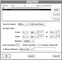
To access the Call Filtering window, pull down the Services menu and choose Call Filtering. The Call Filtering window looks like this:
Figure 6-9 Call Filtering Window
-
Click on Add.
If you need to modify an existing set of parameters, you need to select it from the list of call filtering parameters. To do this, click on the call filtering parameters you want to modify, then click on the Modify button.
-
Select the Service from which to accept calls.
The available services are PAD,TCP-IP, CLNP, OSI, None, or Other. If you select Other, a pop-up window will prompt you to enter the service name, and call user data.
-
Set the time period when calls will be accepted.
You can set this up so that the time period specified is repeated daily or weekly. If you select "one time", the time period will not be repeated.
-
Set the link number from which you will accept calls.
You can restrict which networks you will accept calls from by specifying the link number. If the link number is set to 255, X.25 will accept calls over any link.
-
Specify the calling address of the machine from which calls will be accepted.
If you set the Calling Address to Don't Care, X.25 will accept calls from any address. If you set the Calling Address to Starts with, or Ends with, you must also enter the appropriate numbers. For example, if you want to accept calls that have an X.25 address beginning with 1234, you select Starts with, and enter 1234 in the adjoining field.
-
Click on OK to add the information to the list of Call Filtering parameters and to dismiss the window.
- © 2010, Oracle Corporation and/or its affiliates
