Chapter 8 Example Configurations
This chapter contains additional example configurations that you may find useful. The first two are configurations that can be useful for test purposes: a loopback configuration and a back-to-back configuration.
Note -
In each example, you must first log in as root or become superuser before starting x25tool.
Setting up a Loopback Configuration
A loopback configuration is useful for testing and troubleshooting your local configuration down to, and including, the link layer. Completing a call over a loopback interface is a useful check of your local X.25 and link layer configuration. If you have problems bringing up the X.25 network, a loopback test should be one of the first tests you perform.
Follow the instructions in "Loopback over a WAN (LAPB)" to configure a loopback over LAPB and in "Loopback over LLC2 (LAN Links)" to configure a loopback over LLC2.
Loopback over a WAN (LAPB)
For a loopback configuration over LAPB, you must have two links. Configure these as follows:
-
Display the Link Editor window.
In the x25tool base window, click on Add and select the default template.
-
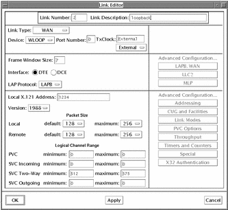
Create the first loopback link by assigning the values shown below:
-
A unique link number
-
WAN as the link type
-
WLOOP as the device type
-
0 as the port number
-
Interface type as DTE
-
LAP protocol to LAPB
-
Any string of digits as the address
Figure 8-1 Creating the First Link in the Loopback Configuration
-
-
Click on OK to apply the changes and to dismiss the window.
-
Create a second link.
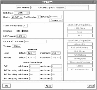
Configure the values as shown below:
-
A unique link number
-
WAN as the link type
-
WLOOP as the device type
-
1 as the port number
-
Interface type as DCE
-
LAP protocol to LAPB
-
Any string of digits as the address
Figure 8-2 Creating the Second Link in the Loopback Configuration
-
-
Click on OK to apply the changes and to dismiss the Link Editor.
-
Save the changes to the configuration.
From the x25tool menu, select File => Save.
-
Stop and restart your X.25 network.
From the Network menu in x25tool, select Stop X.25 Network and Start X.25 Network.
At this point, you have a usable loopback interface for LAPB. You can test it with a command such as the one below. In this example, you have a loopback interface on link 2 with a Remote Address of 1111:
% pad 2.1111
 Break-in sequence is `^Pa'

 Connecting...
 Connected
 Solstice X.29 Terminal Service
 login:
You can connect to the other member of the link pair by specifying its link number and its Local Address. For example:
% pad 3.1234
 Break-in sequence is `^Pa'

 Connecting...
 Connected
 Solstice X.29 Terminal Service
 login:
It is convenient to set up entries for your loopback interfaces in your PAD hosts database. See "Configuring the PAD Hosts Database" for instructions. In the PAD Hosts Database window, you need enter values only for the Host Name, Remote Address, and Link Number parameters.
You can run x25trace in another window and observe LAPB and X.25 Packet Layer activity over the loopback interface. To do this, open another window, log on as root and type:
# /opt/SUNWconn/bin/x25trace -i /dev/lapb
See "Obtaining Packet and Link-Level Traces" for instructions on the use of x25trace.
Loopback over LLC2 (LAN Links)
The LLC2 layer supports loopback by default, using the loopback SAP of 70. To test a loopback connection over LLC2, simply specify your LLC2 link number, MAC address, and SAP address of 70 as arguments to the pad program. For example, if your LLC2 link number is 1 and your MAC (Ethernet) address is 8:0:20:ab:21:6, enter:
% pad 1.080020ab210670 Break-in sequence is `^Pa' Connecting... Connected Solstice X.29 Terminal Service login: |
You can also set up entries for your LLC2 loopback interface in your PAD hosts database. See "Configuring the PAD Hosts Database" for instructions. In the PAD Hosts Database window, you need enter values only for the Host Name, Remote Address (your MAC address plus 70), and Link Number parameters.
To observe LLC2 protocol activity over the loopback interface, you can, as root, enter an x25trace command such as:
# /opt/SUNWconn/bin/x25trace -i /dev/llc2 |
See "Obtaining Packet and Link-Level Traces" for instructions on the use of x25trace.
Setting up a Back-to-Back Test Configuration
If you are using Solstice X.25 to connect to a PSDN, you need to make a call over the PSDN in order to check that your configuration works with it. However, you can test user-developed applications, and certain aspects of your X.25, LAPB, and WAN configuration, by using a null modem cable or modem emulator to set up a "back-to-back" connection to another machine.
Note -
See "Building the Null Modem Cable", for instructions on building a null modem cable.
Follow the instructions in "Back-to-Back WAN Links" to set up a back-to-back WAN connection, and in "Back-to-Back LAN Links" to set up a back-to-back LAN connection.
Back-to-Back WAN Links
This example will work for Solstice X.25 9.x and SunLink X.25 8.x. You can also configure a back-to-back WAN link for SunNet X.25 7.0, but the instructions are slightly different. They have been included in the example.
-
Connect your communications equipment.
If you are using a modem eliminator, connect the cables from the modem eliminator to the two machines. If you are using a null modem cable, connect the cable to the two machines.
-
Create a link on the local machine.
Follow the instructions in "Configuring a Single WAN Link".
In the x25tool windows use the following values:
-
In the Link Editor window, accept ZSH (the default), or specify HSI for the Device item.
-
Choose a speed that is supported by the remote machine for the Tx Clock parameter. If the remote machine is a SunNet X.25 7.0 machine, on that machine enter a command such as:
% grep syncinit /etc/sunlink/x25/rc /usr/sunlink/sync/syncinit zss0 speed=19200 txc=baud rxc=rxc > /dev/console 2>&1
In the example output above, the remote machine is running at 19200 bps. In such a case, specify 19200 for Tx Clock for the local machine.
-
In the Link Editor window, set the Interface parameter to DTE (the default) or DCE. The local machine Interface parameter must be the opposite of the remote end. For example, if the remote machine is a SunNet X.25 7.0 machine, on that machine enter a command such as:
remote_host x25config -d /etc/solstice/x25/x25params0 | grep 198x25 1984 normal dte
In the example output above, the remote machine is a DTE. In this case, you would, specify DCE for the local machine.
-
Still in the Link Editor window, specify a Local Address. Make a note of this address.
-
Under Logical Channel range in the Link Editor window, specify a two-way range that corresponds to the range used by the remote machine. If the remote machine is a SunNet X.25 7.0 machine, on that machine enter a command such as:
remote_host% x25config -d /etc/sunlink/x25/x25params0 | grep way lcn_two_way 512-575
In the example output above, the remote machine has a logical channel range of 512-575, the default for SunNet X.25 7.0. In this case, you would specify the same range for the local machine.
-
Choose an X.25 configuration file that is appropriate for your local DTE/DCE role and for the X.25 recommendation year supported by the remote machine. For example, if the remote machine is a DTE that supports 1984 X.25, select def.dce84.x25.
-
-
Display the PAD Hosts Database widow.
In the x25tool base window, select Services => PAD => PAD Host database.
In the PAD Hosts Database window, click on Add and enter the name of the remote machine in the Host Name field and the DTE or DCE X.121 address of the remote machine in the Remote Address field. If the remote machine is a SunNet X.25 7.0 machine, on that machine enter a command such as:
remote_host% x25config -d /etc/sunlink/x25/x25params0 | grep ^add
address 1000-5555-22
In the example output above, the remote machine has an address of 1000555522. Enter this value (without the hyphens) in the Remote Address field.
After entering the name and address of the remote machine, click on Apply in the PAD Hosts Database Window. Click on OK to dismiss the window.
-
Start the X.25 network.
-
Repeat Steps 2, 3 and 4 of this procedure on the remote machine to bring up the X.25 software on that machine.
If this machine is running Solstice 9.x or SunLink 8.x, perform the steps exactly as described above. If the remote machine is running SunNet X.25 7.0 or another vendor's X.25, create an equivalent configuration.
-
In a terminal window, enter a command such as:
local_host% /opt/SUNWconn/bin/pad remote host
where remote host is the name you entered for the remote host. You should receive a message indicating that your call is connected. If you do not, it indicates a configuration problem on the local or remote end.
Back-to-Back LAN Links
-
Ensure that both machines are connected to the same Ethernet segment or FDDI dual ring or concentrator (or back-to-back with FDDI/S).
-
Create a link on the local machine.
Follow the procedure specified in "Setting up a Workstation Attached to a LAN".
In the x25tool windows use the following values:
-
In the Interface Configuration window, specify LE (Ethernet), FDDI/S, or FDDI/DX for the Device item.
-
Under Logical Channel ranges, specify a two-way range that corresponds to the range used by the remote machine. If the remote machine is a SunNet X.25 7.0 machine, on that machine enter a command such as:
% x25config -d /etc/sunlink/x25/x25params link number llc2 | grep way lcn_two_way 512-575
In the example output above, the remote machine has a logical channel range of 512-575, the default for SunNet X.25 7.0. Specify the same range for the local machine.
-
-
Display the PAD Hosts Database window.
In the x25tool base window, click on Service => PAD => PAD Hosts Database.
-
Enter information about the remote machine.
In the PAD Hosts Database window, click on Add and enter the name of the remote machine in the Remote Host Name field and the MAC address of the remote machine in the Remote X.121 Address field. Append the value 7e (the LSAP address that designates LLC2) to the MAC address.
If the remote machine is on the same Ethernet segment or FDDI ring, you can obtain its MAC address by entering the commands shown below on the local machine:
local_host% arp remote-hostname remote-hostname (129.144.41.29) at 8:0:20:10:b5:a2
In the example output above, the last field on the second output line, 8:0:20:10:b5:a2, is the MAC address. You can copy-and-paste arp output into the Remote Address field and append :7e to form a full LSAP address.
After entering the name and address of the remote machine, click on Apply in the PAD Hosts Database Window. Click on OK to dismiss the window.
-
Start the X.25 network.
You do not need to do this if your X.25 network is already up, and you made no changes in the Link Editor window.
-
Repeat Steps 2, 3 and 4 of this procedure on the remote machine to bring up the X.25 software on that machine.
If this machine is running the current release of Solstice X.25, perform the steps exactly as described above. If the remote machine is running SunNet X.25 7.0 or another vendor's X.25, create an equivalent configuration.
-
In a terminal window, enter a command such as:
hostname% /opt/SUNWconn/bin/pad remote host
where remote host is the name of the remote host.
You should receive a message indicating that your call is connected. If you do not, there is a configuration problem on the local or remote end.
Setting up a Server to Receive PAD Calls
In this example, a server is attached to a PSDN. It needs to be configured so that remote machines can access it using the PAD.
Figure 8-3 Setting up a Server to Receive PAD Calls
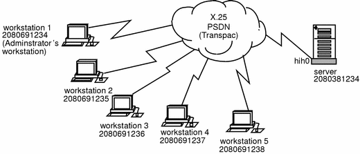
In the example:
-
All remote workstations are running Solstice X.25 and can access the server. The server must be configured to use Solstice X.25 and to receive PAD calls from the other workstations.
-
Workstation 1 is used by the system administrator when at the remote site. It needs full terminal-type access to the server.
-
The other machines are used by employees at the remote site. The system administrator has written an application to drop calls to the server straight into a menu system that gives them access only to the information they need.
To create this kind of configuration you need to:
-
Create a link between the server and the PSDN.
-
Configure the logical channel ranges, and any other optional parameters, used by each PSDN.
-
Configure the PAD Listen Database.
Note -
The workstations must also be configured so that they can access the server. Refer to "Configuring the PAD Hosts Database" in Chapter 6, Configuring Solstice X.25 Services for instructions.
Configuring the WAN Link
First, create a link between the server and the PSDN:
-
From the x25tool menu, select Edit => Add. The list of templates will appear. Select TRANSPAC.
-
Create a link to the PSDN.
Edit the default values to match those required by the PSDN:
-
Adjust the logical channel ranges to match those used by the PSDN.
Enter the values assigned by your PSDN. If there are no values assigned to a particular LCR, leave both minimum and maximum as 0.
Configuring Parameters
Once you have created the link, you may also need to configure other packet layer and LAPB layer parameters. To access them from the Link Editor window, select LAPB, WAN. Which values you need to change depends on the PSDN you are attaching to, and on your own configuration.
For more information, see Chapter 7, Parameter Reference.
-
Click on OK to apply the changes and dismiss the window.
Configuring the PAD Daemon Listen Database
Next, configure the PAD Daemon Listen Database. This determines how the server will handle incoming PAD calls.
-
In the x25tool main window, click on Services, then select PAD => PAD Daemon.
This brings up the PAD Daemon Listen Database window.
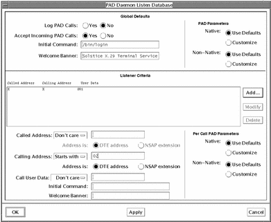
Figure 8-4 Configuring the PAD Daemon Listen Database
-
Configure the Global default values.
These will be used for incoming calls from all machines except the one reserved for the administrator's use. In the top part of the screen, specify that all incoming calls are to start the menu application immediately. The Solstice X.25 9.2 system software does not include a menu driven application program. You need to write the application, then use the Initial Command parameter to call it.
-
Add a new "perhost" entry for the system administrator's workstation.
In the middle part of the window, add an entry to the list for the machine used by the system administrator. Click on Add, then set Calling Address to Matches. Next to Calling Address Matches, type in the name of the remote machine. Finally, specify the Welcome Banner, and the Initial Command parameters to determine what should happen when a call is received from that address. If you leave the Initial command line blank, /bin/login is launched by default.
-
Click on OK to apply the changes and to dismiss the window.
Once you have finished configuring the PAD Daemon Listen Database, you are ready to start Solstice X.25 by pulling down the Network menu and choosing Start X.25.
You can check that your configuration is working correctly by trying to make a PAD call from a remote machine.
Setting Up a Server to Operate as an IP Router
In this example, Server A has Solstice X.25 installed. This lets it route TCP/IP traffic and provide a connection to the X.25 PSDN for any machine attached to the same LAN. The other machines on the LAN do not need to run X.25 themselves in order to connect to remote devices across the WAN.
Figure 8-5 Setting Up a Server to Operate as an IP Router

Note -
A machine does not need to have X.25 configured on its LAN interface in order to be able to act as a router between a LAN and a WAN. IP will handle sending traffic to the router. X.25 is needed to provide the logical connection to the WAN.
To make a configuration like this, you need to:
-
Configure the link between the server and the WAN.
-
Configure the logical channel ranges, and any other optional parameters, used by the PSDN.
-
Configure the values used for routing IP.
Configuring the WAN Link
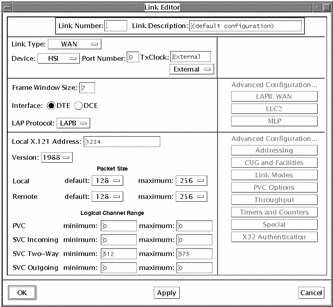
First, configure the link between the server and the WAN. This example uses a High Speed Interface.
-
Bring up the Link Editor window.
From the Edit menu, select Add. Select Tymnet from the template list.
-
Change the other values as shown in the snapshot below.
Refer to "x25tool Overview" for help if you do not know how to change the values.
Figure 8-6 Configuring a Link Between the Server and the WAN
-
Adjust the logical channel ranges to match those used by the PSDN.
Enter the values assigned by your PSDN. In the example, there are 63 two way SVCs, numbered from 512 to 575, inclusively. Since there are no PVCs, or one way SVCs, these fields are left as 0.
-
Click on OK to apply the changes and dismiss the window.
Configuring Parameters
Once you have created the link, you may also need to configure other packet layer and LAPB layer parameters. To access them, from the Link Editor window, select LAPB, => WAN. Which values you need to change depends on the PSDN you are attaching to, and on your own configuration. For more information, see Chapter 7, Parameter Reference.
Configuring IP Routing
Now you are ready to set up the values that will be used for routing IP.
-
Pull down the Services menu and choose IP => IP Interface. The IP Interface Configuration window appears.
-
Enter the information about the IP network that this router will attach to.
Click on the Add button. The snapshot below summarizes the changes you need to make for this example configuration:
Figure 8-7 Configuring the IP Routing
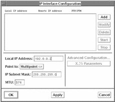
You always need to specify the local IP address. You should also specify the IP subnet mask. To use the network default, leave the subnet mask field blank.
Once you have made the changes, click on Apply. In most instances, the default settings are sufficient, but if you need to change the default X.25 parameters, click on Modify, then click on the X.25 Parameters button to access the X.25 Configuration for IP Interface window.
The snapshot below summarizes the changes you need to make for this example configuration:
Figure 8-8 Configuring the X.25 Parameters for the IP Interface
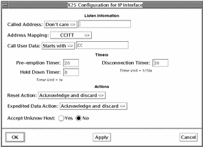
Unless you are connecting to the Defense Data Network (DDN), specify CCITT address mapping.
To restrict access and so add a measure of security, you can choose not to accept calls from unknown hosts. A host is unknown if its address is not included in the Remote Host to X.25 Address Map. Refer to "IP Interface Configuration".
The Listen Information is useful if the machine you are configuring has more than one address. You can use it to restrict which address(es) will respond.
You can also filter incoming calls based on their Call User Data. Take care not to delete the initial CC if you are using this parameter--this specifies that calls are for IP. Without the initial CC, calls will fail. Refer to "IP Interface Configuration" for more detail.
-
Configure information mapping remote IP addresses to remote X.25 addresses.
Pull down the Services menu and choose IP => IP Mapping. The Remote IP Host to X.25 Address Map window appears. The snapshot below summarizes the information you need to add. Again, you can keep most of the default values:
Figure 8-9 Information Mapping of Remote IP Addresses to Remote X.25 Address.
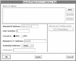
You can enter a host name which has been defined in /etc/hosts in place of the remote IP address.
-
Click on OK to save the changes and to dismiss the window.
-
Start X.25 by pulling down the Network menu and clicking on Start X.25.
To check that the configuration works, try to ping the remote machine or to rlogin.
Setting up a Server with Multiple WAN Links
In this example configuration, the server is connected to three different PSDNs. It will be used primarily by users who want to make PAD calls to machines on the remote network.
Figure 8-10 Setting up a Server with Multiple WAN Links
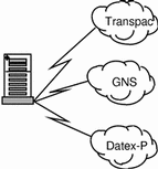
To set up a configuration like this, you need to:
-
Create a link to each PSDN.
-
Configure the logical channel ranges, and any other optional parameters, used by each PSDN.
-
Set up X.25 routing, so that traffic can automatically be sent out on the correct link.
Configuring Three WAN Links
Figure 8-11 Configuring the WAN Links
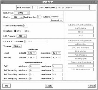
The first step in creating this configuration is to create the three WAN links. Start x25tool, click on Add Link and select the template configuration (Transpac, GNS or Datex-P) to bring up the Link Editor window. Create three links, using the appropriate values for each. In the snapshot, the link parameter values apply to Datex-P, and will be added to the Links Configuration list in x25tool when the administrator clicks on the template entry.
When configuring the WAN links, pay particular attention to the logical channel ranges. Different PSDNs allocate different values. Make sure you set the correct values for each link.
In the same way, change any relevant LAPB and WAN values. Which values you need to change depends on the PSDN you are attaching to and on your own configuration.
Note -
This example uses three HSI interfaces. You can also mix links that use the onboard serial port (zsh) and links that use high speed interfaces. However, you cannot run Solstice X.25 on more than two onboard serial ports on the same machine.
Configuring Parameters
Once you have created the three WAN links, you may need to configure other packet layer and LAPB layer parameters.
-
Change any other X.25 Parameters for this link.
Different PSDNs may require you to change different packet layer parameters.
-
Save your changes.
Configure X.25 Routing
When you have multiple links, you must tell your machine which traffic should go out on which link. There are several ways of doing this. Which one you use depends on which applications you are running over your X.25 links. The advice given below applies to the PAD program supplied with Solstice X.25 and to IP routing. You can determine the link to use as follows:
-
When making PAD calls, the user can specify the link to use as part of the address. For example, to call the address 2080381111 using link 0, the user could enter:
% pad 0.2080381111 |
If your users are calling only a small number of remote machines this may be the easiest option, as it does not require any special configuration. Other applications may also allow you to specify a link when making a call.
-
For PAD calls, you can make entries in the PAD Daemon Listen Database that specify the address and link number of a remote machine, and provide an alias that users can use when making calls. Refer to "Configuring the PAD Hosts Database" for more information. Using this option saves users from having to remember remote addresses and link numbers.
-
For IP, when you make an entry in the Remote IP Host to X.25 Address Map, you can specify the link to use to reach each remote IP address. See "Configuring Solstice X.25 to Route IP" in Chapter 6, Configuring Solstice X.25 Services. Or, you can use automatic routing, if you have multiple links. See "Routing"" in Chapter 7, Parameter Reference.
-
You can use automatic routing. For PAD calls and other applications, you can use the X.25 Routing table. This is the most practical option where there are a large number of remote machines. Making a PAD Hosts Database entry for each one could quickly become unwieldy. The rest of this section looks at how to configure X.25 routing.
Note -
The X.25 Routing table is also used in dial-up configurations. Refer to "Configuring the X.25 Routing Table".
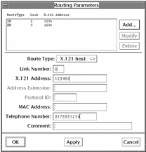
To display the X.25 Routing window, select Routing, under Services Configuration in the X25tool window. The Routing Parameters window appears. When the window first appears, the parameters are all grayed out. To fill in the parameters:
-
Click on Add, then select Top, Bottom, Before, or After to determine where in the list to add the new entry.
The Routing Parameters window looks like this:
Figure 8-12 Configuring the Routing Parameters Window
-
Enter the number of the link that reaches this destination.
This is the number you assigned to the link when you created it.
-
Configure the Route Type.
-
For an individual remote host, choose X.121 Host or AEF Host.
-
For a to a group of similar addresses, choose X.121 Prefix or AEF Prefix.
-
For all calls unless otherwise specified, choose X.121 Default or AEF Default.
In the example, calls are being routed to three different remote networks. Each remote network address starts with a unique 4 digit sequence, so X.121 Prefix is the appropriate Route Type to choose in all three cases.
Note -AEF addresses are used on OSI networks. Use AEF addresses instead of X.121 addresses if your network uses the OSI protocol stack instead of the TCP/IP protocol stack.
-
-
Enter the X.121 address prefix.
You need to enter enough digits here to distinguish the remote network clearly, without adding so many that you limit which destinations can be reached on the remote network. The 4 digits shown in the example clearly identify each network without restricting calls to part of the network.
Note -When making international calls, some PSDNs require you to precede the X.121 address with a code indicating that this is an international call. For example, to make an international call from Germany, you must add a 0 to the front of the X.121 address. If you are configuring international calls and this applies to your PSDN, make sure you include this as part of the X.121 address prefix.
-
Enter a comment (optional).
You could identify the destination that this link reaches, for example.
-
Save your changes and dismiss the window.
Click on Apply, then click on OK to dismiss the Routing Parameters window.
Once you have finished adding routes, you are ready to start the Solstice X.25 software. Start X.25 by pulling down the Network menu and choosing Start X.25.
You can check that your configuration is working correctly by trying to make a PAD call to a machine on one of the remote networks.
Setting up a Dial-up Link Configuration
In this example, the workstation is running Solstice X.25 so that it can dial into the PSDN. A modem provides the connection to the PSDN.
Figure 8-13 Setting up a Dial-up Link Configuration

As there is a server on the corporate network that is attached to the same PSDN, the workstation can access the server, for example, by making a PAD call. From there, it can rlogin to other machines on the corporate network. Alternatively, the server could be configured to act as an IP router, giving direct access to the whole network. To configure a machine to use a dial-up connection:
-
Create a link to the PSDN.
-
Configure the logical channel ranges.
-
Specify that V25bis calling procedures are to be used.
-
Set the idle disconnect timer to a reasonable value.
-
Configure X.32 authentication procedures.
-
Add the telephone number of the point of connection to the network (in this case a modem) to the X.25 Routing table.
Note -
Before configuring Solstice X.25 9.2, you must configure your modem to operate in V.25bis mode--refer to your modem manufacturer's documentation for instructions that apply to your particular modem.
Configuring the WAN Link to the PSDN
First configure the link between the server and the PSDN. In the example this is the onboard serial port connected to the modem.
-
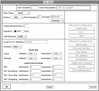
Edit Link 0, the default WAN link.
Click on the entry for Link 0 in the scrolling list, then click on Modify Link.
-
Change the other values as shown in the snapshot below.
Refer to "x25tool Overview" for help if you do not know how to change values:
Figure 8-14 Modifying a WAN Link Configuration
-
Click on Apply to update the configuration.
Configuring the Idle Disconnect
You will need to set the Idle Disconnect. This is the period of time, in tenths of a second, that the link will remain idle before closing down.
-
From the Link Editor, select Timers and Counters.
The Timers and Counters button is located under Advanced Parameters.
-
Set the Idle Disconnect.
Set a value (in tenths of a second) that is high enough to allow for lost traffic and retries, but low enough that you are not constantly paying for an idle link.
-
Click on OK to update the configuration and return to the Link Editor.
-
Click on OK to update the configuration and exit the Link Editor.
Configuring Parameters
Once you have created the link, you need to specify that V25 calling procedures are to be used, and set the idle disconnect to a reasonable value.
Configuring V.25bis Calling Procedures
V.25bis calling procedures are used to control the modem for a dial-up link. You must specify that V.25bis calling procedures are to be used. The parameters you need are located in the LAPB and WAN Parameters window. To configure the parameters:
-
Display the LAPB and WAN Parameters window.
In the Link Editor, click on the LAPB,WAN button, which is located under Advanced Configuration. The LAPB and WAN Parameters window appears.
-
Choose V25 Calling procedures.
Pull down the Calling Procedure menu and choose V25.
-
Set the V25 Call Request Timer.
This determines the length of time, in tenths of a second, that your machine will continue trying to connect to the remote network before timing out. If your modem supports call fail indications, set the V25 Call request timer to 0. Check with your modem supplier to find out if this is the case.
Configuring X.32 Authentication Procedures
Next you need to configure the X.32 authentication procedures. These are used on dial-up links by most PSDNs, to prevent people without permission from dialing in. To configure X.32 authentication:
-
Set Enable X.32 Authentication to Yes.
You can choose to carry out X.32 authentication at link level or a packet level. When connecting to a PSDN, use link level as this means the authentication is carried out by the network. Packet level is appropriate when connecting with another machine (back to back, for example) when you want the machine and not the network to do the authentication. Both the Identity and the Signature can be any hexadecimal string, up to 32 characters long, not containing whitespace.
-
Click on OK to exit the LAPB and WAN parameters window.
-
Save the configuration.
This makes sure your changes will be used when you start X.25. From the x25tool main menu select File => Save, and save the changes to the current configuration. Or you can select File => Save As, to save the changes in a different configuration.
Configuring the X.25 Routing Table
The final step in configuring a dial-up machine is to add the telephone number for the network point of connection to the X.25 routing parameters table so that it is mapped to the X.121 address of the machine you want to be able to access. In the example, this is a host on the remote network that is configured to act as an IP router, providing access to the remainder of the network.
To display the X.25 Routing table, in the x25tool window, pull down the Services menu and click on Routing. The X.25 Routing parameters table applies across all links. To configure:
-
Click on Add, then select Top.
When the window first appears, the parameters are all grayed out. Clicking on Add, Top creates a new template entry and specifies that the entry will go at the top of the list.
-
Select the Route Type.
The example uses a route to an individual host, so choose X.121 Host.
-
Enter the number of the link that reaches this destination.
This is the number you assigned to the link when you created it. In the example this is link 0.
-
Enter the address of the server on the corporate network that also has a connection to the X.25 PSDN.
-
Enter the Telephone Number used to reach this destination.
In a dial-up configuration, this is the address of your point of attachment to the X.25 PSDN, in most cases a modem.
-
Enter a comment (optional).
You could identify the destination that this link reaches, for example.
-
Save your changes.
Pull down the File menu and choose the Save option.
The completed Routing window for this example looks like this:
Figure 8-15 Routing Parameters Window

This configuration creates a mapping between the telephone number and the X.121 address of the remote host. When the machine has traffic for the remote host, it knows to dial into the X.25 PSDN. The traffic will then be routed to the remote machine.
Setting up a Workstation Attached to a LAN
Figure 8-16 Setting up a Workstation Attached to a LAN

In this example, a new workstation is being added to the Local Area Network (LAN). When installed on a machine attached to a LAN, X.25 is configured over LLC2 instead of over LAPB.
This kind of configuration is straightforward. You only need to configure the link to the LAN. The default parameters used at both the Packet layer and the LLC2 layer should work in almost all LAN configurations.
To configure a LAN link:
-
Start x25tool.
-
In the Links Configuration list, select Link 1, then click on Modify to bring up the Link Editor window.
You can use Link 1 as a template.
-
Configure the values for your LAN link, as shown below:
Figure 8-17 Configuring LAN Link Values
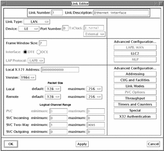
You can keep almost all of the default values. The Local Address is the MAC address of your machine. You can find it out by entering the following command:
hostname% arp machinename
-
Click on Apply.
Should you need to change the Local SAP or Loopback SAP, you can now do this by selecting Addressing, under Advanced Configurations. However, in most instances the default settings should work. Make sure that you do not change or delete the Local SAP or the Loopback SAP, unless you are certain that your network uses different values.
Once you have added the LAN link like this, you can start the X.25 software. You should now be able to run your applications over the LAN.
For example, you can make PAD calls to machines on the same LAN by specifying the link number and the MAC address, followed by the SAP, as shown below:
hostname% pad 1.0800207111117e
where 1 is the link number, 080020711111 is the MAC address, and 7e is the SAP.
See "Configuring the PAD" for information on adding entries to the PAD Hosts Database.
Note -Even if the LAN link is the only link on your machine, you need to specify the link number when using applications such as the PAD. This is because Solstice X.25 defaults to use the lowest numbered WAN link. If there is no WAN link, there is no default link. Another way to deal with this situation is by using the X.25 Routing table. Map the MAC address plus link number to an X.121 address, then make calls to the X.121 address rather than the MAC address. See "Configure X.25 Routing" for an example of configuring the X.25 Routing table.
Setting up a WAN and a LAN Link on a PC Running X.25
This section describes how to configure a WAN and a LAN link on a PC running Solstice X.25. The configuration described in this chapter uses the default values provided with the product.
Figure 8-18 Setting up a WAN and a LAN Link on a PC Running X.25
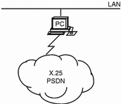
The configuration process is identical to that used for the SPARC version of the product, but the device names change.
To configure Solstice X.25 to be used over the WAN, you need to:
-
Configure some information about the link
-
Change the logical channel ranges used by the Solstice X.25 software to match those used by your PSDN
Before you start, make sure you know the following information:
-
The logical channel ranges used by the PSDN
To configure the LAN link, you only need to configure the link to the LAN. The default parameters used at both the Packet layer and the LLC2 layer should work in almost all LAN configurations.
Installing Your WAN Card
In order to run Solstice X.25 9.2 over the WAN, the PC must have an appropriate WAN card installed. Install this as described in the manufacturers instructions. You must use a different interrupt setting for each card that you install--consult your PC manufacturer's documentation for instructions on finding out which interrupts and i/o addresses are available.
Creating the LAN and WAN links.
By default, there are two template links already configured, one WAN link and one LAN link.
First, you will configure a single WAN link by editing the WAN template.
-
In the x25tool window, make sure the entry for Link 0 in the scrolling list is highlighted. Select Modify.
The Link Editor window appears.
-
Set the Device type and Port Number.
The example uses the default expx device, which is the device type for the SCiiExpress-X card. Currently, this is the only available device for WAN links:
-
Make sure the Interface is set as DTE.
The only time you will need to set the Interface as DCE is if you are running two machines back-to-back, for example for testing.
-
Set the LAP Mode to LAPB, unless you are sure your PSDN uses a different LAP Mode.
LAP and LAPBE are used very rarely.
-
Set the Local Address.
Type in the address of port 0 in this field. This is the X.121 address assigned to you by your supplier. This address is often referred to as an X.25 address. Your service supplier should tell you this address.
Note -The Full Address and Extended Address parameters are not used when the product is in normal operation. You only need to enter these if you are using an application that expects to read them. If this is the case with your PSDN, your service provider will tell you what you need to enter here.
-
Select the Version.
Pull down the Version menu and choose the version of the X.25 recommendation used by your PSDN.
-
Set the Logical Channel Range.
Your PSDN will tell you which values to use here. Contact them if you require this information. If you are configuring a private network, all machines on the network must use the same logical channel ranges. In this case, you can choose any values that comply with the X.25 Recommendations.
-
Click on Apply to confirm your changes.
Next create the LAN link.
Using link 1 as a template, configure the values for your LAN link. You can keep almost all of the default values. The device type depends on the type of Ethernet card used by your PC. The default ELX-0 applies to the 3Com® Etherlink® III card. If you are not sure of the device type used by your PC, enter the following command:
hostname% ifconfig -a
Included in the information returned by this command is the name of the device that IP is running over. Use this same device type for X.25.
The Local Address is the MAC address of your machine. You can find it out by entering the following command:
hostname% arp machinename
-
Click on Apply.
-
In the x25tool main window, pull down the File menu and select Save.
This makes sure your changes will be used next time you start X.25.
Note -For a default configuration, you do not need to configure the Datalink layer parameters; the defaults should be adequate.
-
Start X.25 by pulling down the Network menu and clicking on Start X.25.
To check that the configuration is valid, make a PAD call to yourself. To do this, enter the pad command at a command line, followed by your own X.121 address:
hostname% pad X.121 address
Once you have created a link that works, you can fine-tune it, or configure the application(s) you want to run over it. The procedure for doing so is the same as for the SPARC version of the product.
- © 2010, Oracle Corporation and/or its affiliates
