3.14.2 What to Do
-
Remove the main logic board from its antistatic packaging and place it on an antistatic mat.
 Caution -
 Handle the main logic board by the back panel or edges only.
-
Set the jumper settings on the replacement main logic board so that they match the jumper settings on the original main logic board.
See "3.15 How to Set the Serial Port Jumpers" and "3.16 How to Set the Flash PROM Jumpers".
-
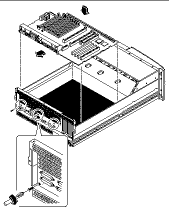
Position the replacement main logic board in the chassis.
Align the notches on the sides of the board with the corresponding tabs on the chassis.

-
Slide the main logic board toward the back of the system.
Ensure that each connector on the main logic board slides through the corresponding cutout in the chassis back panel.
-
Replace the three screws securing the main logic board to the system back panel.
-
Connect the following internal cables to the main logic board.
The connectors are keyed to connect in only one way. For information about cable connector locations, see "5.5 How to Connect the System Cables".
- © 2010, Oracle Corporation and/or its affiliates
