Chapter 3 Servicing the Main Logic Board and Components
This chapter describes how to remove and replace the system main logic board and main logic board components. For a list of part numbers for field-replaceable units and optional equipment, see Appendix D, Illustrated Parts Breakdown.
The following tasks are covered in this chapter:
3.1 How to Remove a Memory Module
Memory modules for this system are dual inline memory modules (DIMMs). Each DIMM bank must contain four DIMMs of equal density (for example, four 64-Mbyte DIMMs) to function properly. Supported DIMM configuration options are 32, 64, and 128 megabytes. See the Sun Enterprise 220R Server Owner's Guide for more information.
3.1.1 Before You Begin
Complete these tasks:
DIMMs are made of electronic components that are extremely sensitive to static electricity. Static electricity from your clothes or work environment can destroy the DIMM. Always wear a grounding strap when you handle the modules.
Do not remove any DIMM from its antistatic packaging until you are ready to install it. Handle the modules only by their edges. Do not touch the components or any metal parts. Always wear a grounding strap when you handle the modules.
3.1.2 What to Do
-
Locate the memory module(s) to be removed.
-
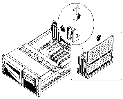
Push the ejection lever away from the memory module and eject it from the socket.
-
Grasp the top corners of the memory module and pull it upward and out of its socket.
-
Place the module on an antistatic mat.
-
Repeat Steps 2, 3, and 4 for each memory module being removed.
3.1.3 What Next
To install a memory module, complete this task:
3.2 How to Install a Memory Module
Memory modules for this system are dual inline memory modules (DIMMs). Each DIMM bank must contain four DIMMs of equal density (for example, four 64-Mbyte DIMMs) to function properly. Supported DIMM configuration options are 32, 64, and 128 megabytes. See the Sun Enterprise 220R Server Owner's Guide for more information about memory.
3.2.1 Configuration Rules
The following memory configuration rules apply to your system:
-
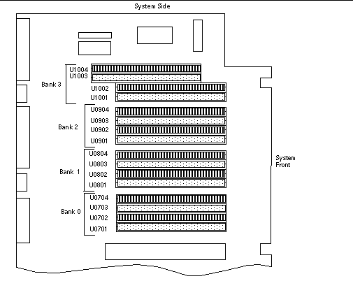
At least one memory bank (all four bank slots) must be filled for the system to boot.
-
DIMMs must be added four at a time within the same bank.
-
DIMM capacities can differ from one bank to the next--for example, four 64-Mbyte DIMMs installed in bank 0 and four 128-Mbyte DIMMs installed in bank 2 is permissible.
Refer to the following diagram for memory locations in your system.
3.2.2 Before You Begin
Complete these tasks:
DIMMs are made of electronic components that are extremely sensitive to static electricity. Static electricity from your clothes or work environment can destroy the DIMM. Always wear a grounding strap when you handle the modules.
Do not remove a DIMM from its antistatic packaging until you are ready to install it. Handle the modules only by their edges. Do not touch the components or any metal parts. Always wear a grounding strap when you handle the modules.
3.2.3 What to Do
-
Remove the new memory module from its antistatic packaging.
-
Locate the socket into which you will install the module.
-
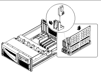
Position the module so that the small notch on the bottom corner of the module is at the same end as the socket's ejection lever.
-
Align the module with its socket until it contacts the socket evenly along the socket's length.
-
Press firmly down on both corners of the module until the bottom edge is firmly seated in the socket.
You will hear a clicking sound when the module is fully seated.
-
Repeat Steps 3 through 5 for each module you want to install.
3.2.4 What Next
Complete this task to reassemble the system:
When you are ready to restart the system, be sure to run OpenBoot Diagnostics tests to verify that the system functions correctly with the new parts you have just installed. For additional information, see:
3.3 How to Remove a PCI Card
3.3.1 Before You Begin
Complete these tasks:
3.3.2 What to Do
-
Disconnect any external cable(s) attached to the faceplate of the PCI card.
-
Disconnect any cables connected to the PCI internal connectors.
-
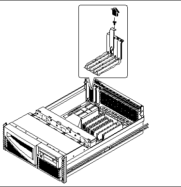
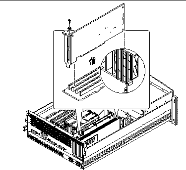
Using a Phillips #2 screwdriver, remove the screw that secures the card to the system back panel.
 Caution -
 Do not apply excessive force to one end or one side of the board. Doing so could damage the card.
-
Pull the PCI card from its slot.
Hold the card by the faceplate and its opposite edge, and pull upward while rocking the card from end to end until it is freed from its slot.
-
Place the PCI card on an antistatic mat.
-
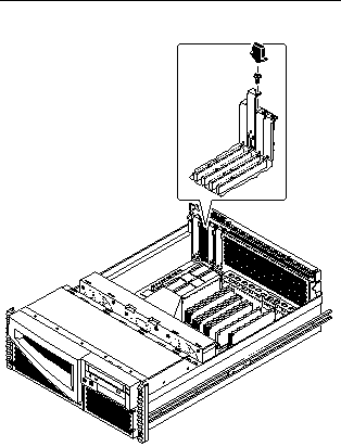
If you are not replacing the PCI card, cover the vacated space with a PCI filler panel.
-
Slide the filler panel into the appropriate slot.
-
Replace the Phillips screw that secures the filler panel to the system back panel.
-
3.3.3 What Next
To install a PCI card, complete this step:
3.4 How to Install a PCI Card
3.4.1 Before You Begin
Complete these tasks:
Read the documentation supplied with the PCI card for information about jumper settings, PCI slot requirements, and cable connections.
For information about the system's PCI slots and locations, see "C.1.2 PCI Bus".
3.4.2 What to Do
-
If you are installing a PCI card in an unused slot, remove the corresponding filler panel from the back of the system. Otherwise go to Step 2.
-
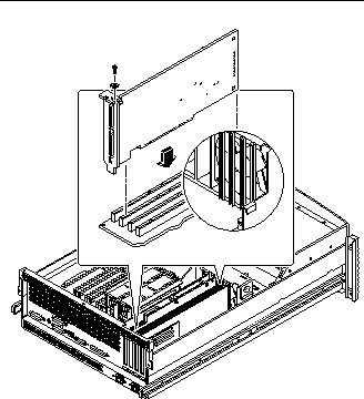
Insert the PCI card into the appropriate slot on the main logic board.
-
Insert the faceplate end of the card into the appropriate opening in the back panel.
If you are installing a PCI long card, guide the opposite end of the PCI card into the card slot on the fan tray assembly.
-
Push the card into the corresponding connector on the main logic board.
Apply even pressure along the edge of the card.
-
-
Secure the PCI card faceplate to the back panel with the Phillips screw.
-
If necessary, connect any internal cables to the PCI card's internal connectors.
-
If necessary, connect any external cables to the PCI card.
3.4.3 What Next
Complete this task to reassemble the system:
When you are ready to restart the system, be sure to run OpenBoot Diagnostics tests to verify that the system functions correctly with the new parts you have just installed. For additional information, see:
You must also perform a reconfiguration boot so that your system is able to recognize the new PCI card. For additional information, see:
3.5 How to Remove a CPU Module
3.5.1 Before You Begin
Complete these tasks:
3.5.2 What to Do
-
Determine which CPU module must be removed from the CPU card cage on the main logic board.
For information about the CPU module location, see "3.6 How to Install a CPU Module".
-
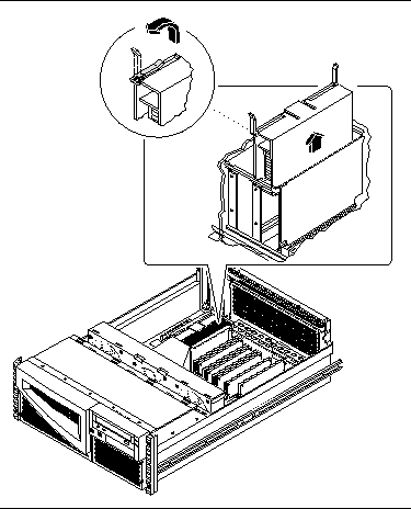
Pull the CPU module ejection levers up from the CPU module to disengage the module from its main logic board connector.
The ejection levers are located on each side of the front of each CPU module. Rotate the levers away from the center of the CPU module.
-
Grasp the upper corners of the CPU module and slide the module out of the CPU card cage.
-
Place the CPU module on an antistatic mat.
3.5.3 What Next
To install a CPU module, complete this task:
3.6 How to Install a CPU Module
3.6.1 Before You Begin
Complete these tasks:
The system supports one and two CPU module configurations. When replacing or installing CPU modules, you must fill the CPU slots in the following order.
|
System Configuration |
Main Logic Board CPU Slot |
|---|---|
|
One CPU |
CPU slot 0 |
|
Two CPUs |
CPU slots 0 and 1 |
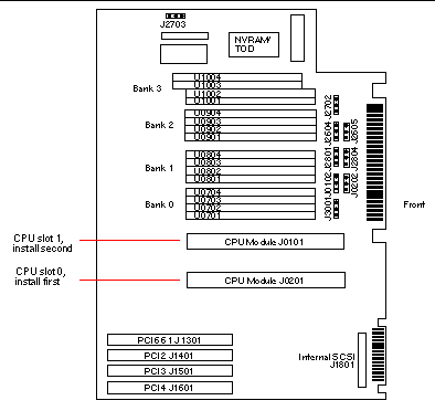
For further information about CPU modules, see your Sun Enterprise 220R Server Owner's Guide.
3.6.2 What to Do
-
Locate the appropriate slot for the CPU module that you are installing in the CPU card cage on the main logic board.
-
Align the edges of the CPU module board with the corresponding grooves in the CPU card cage.
-
Verify that the two ejection levers are open.
-
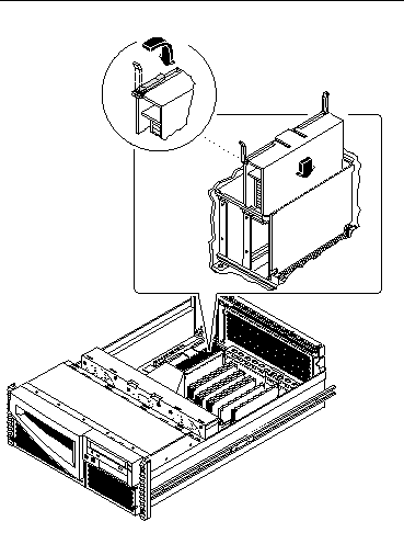
Slide the CPU module evenly into the grooves in the CPU card cage.
Push down until the CPU module meets the connector at the bottom of the CPU card cage.
-
Engage the notch in each lever with its side of the CPU card cage.
-
Simultaneously push both levers toward the center of the CPU module until the CPU module seats in its connector.
3.6.3 What Next
Complete this task to reassemble the system:
When you are ready to restart the system, be sure to run OpenBoot Diagnostics tests to verify that the system functions correctly with the new parts you have just installed. For additional information, see:
3.7 How to Remove the NVRAM/TOD Module
3.7.1 Before You Begin
Complete these tasks:
The non-volatile random access memory/time of day (NVRAM/TOD) module contains the system host identification (ID) and Ethernet address. You may be migrating a functioning NVRAM/TOD module to a new main logic board in order to preserve host ID information. However, if you are replacing a defective NVRAM/TOD module and want to retain the same host ID, consult your authorized Sun sales representative or service provider.
3.7.2 What to Do
-
Locate the NVRAM/TOD module and its carrier on the main logic board.
-
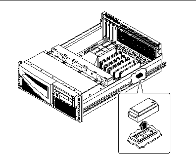
Grasp the NVRAM/TOD carrier assembly at each end and pull straight up.
If necessary, gently rock the NVRAM/TOD from side to side to facilitate removal.
-
Place the NVRAM/TOD module and carrier on an antistatic mat.
3.7.3 What Next
To replace the NVRAM/TOD module, complete this task:
3.8 How to Replace the NVRAM/TOD Module
3.8.1 Before You Begin
Complete this task:
Note -
If you are installing a new NVRAM/TOD module, the NVRAM/TOD must be programmed by a Sun authorized service representative before your system can resume normal operation. If you are installing a new main logic board, remember that you can migrate your former NVRAM/TOD module in order to preserve your system's host ID and Ethernet address.
Note -
For information about setting the flash PROM jumpers to enable you to program the NVRAM, see "3.16 How to Set the Flash PROM Jumpers".
3.8.2 What to Do
-
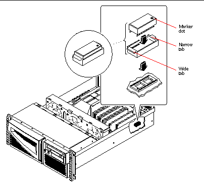
Insert the NVRAM/TOD module and its carrier into its socket on the main logic board.
The carrier is keyed to ensure correct installation of the NVRAM/TOD module into its socket on the main logic board. Make sure that the NVRAM/TOD module is placed into its carrier correctly. The small marker dot on the top of the NVRAM/TOD module should be on the same side as the narrow tab on the carrier assembly.
-
Push down firmly on the NVRAM/TOD module until it seats in its socket.
3.8.3 What Next
Complete the following task to reassemble the system:
When you are ready to restart the system, be sure to run OpenBoot Diagnostics tests to verify that the system functions correctly with the new part you have just installed. For additional information, see:
3.9 How to Remove the Air Guide
3.9.1 Before You Begin
Complete these tasks:
3.9.2 What to Do
-
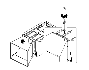
Remove the Phillips screw attaching the air guide to the CPU card cage.
-
Lift the air guide up from the CPU card cage.
3.9.3 What Next
To replace the air guide, complete this task:
3.10 How to Replace the Air Guide
3.10.1 Before You Begin
Complete this task:
3.10.2 What to Do
-
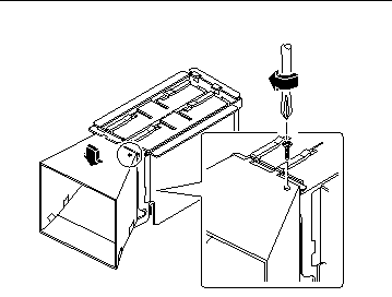
Position the air guide on the CPU card cage assembly.
Align the two tabs on the top of the air guide with the slots on the CPU card cage assembly.
-
Replace the Phillips screw attaching the air guide to the side of the card cage.
3.10.3 What Next
Complete the following task to reassemble the system:
3.11 How to Remove the CPU Card Cage Assembly
3.11.1 Before You Begin
Complete these tasks:
Note -
Remove all CPU modules prior to removing the card cage.
3.11.2 What to Do
-
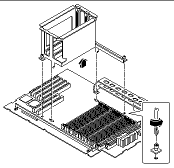
Loosen the two captive screws securing the CPU card cage assembly to the main logic board.
Use a Phillips #2 screwdriver to loosen the screws.
-
Lift the CPU card cage assembly from the main logic board.
3.11.3 What Next
To replace the CPU card cage assembly, complete this task:
3.12 How to Replace the CPU Card Cage Assembly
3.12.1 Before You Begin
Complete this task:
3.12.2 What to Do
-
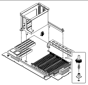
Position the CPU card cage assembly on the main logic board.
-
Align the CPU card cage assembly screw holes with the corresponding holes on the main logic board.
-
Tighten the two captive screws that secure the CPU card cage assembly to the main logic board.
Use a Phillips #2 screwdriver to tighten the screws.
3.12.3 What Next
Complete these tasks to reassemble the system:
3.13 How to Remove the Main Logic Board
3.13.1 Before You Begin
Use an antistatic mat when working with the main logic board. An antistatic mat provides the cushioning required to protect under the board, to prevent the main logic board from flexing, and to provide antistatic protection.
Perform this procedure on a workbench. Sun Microsystems does not support changing the main logic board while the system is installed in a rack.
The NVRAM/TOD module contains the system host identification (ID) and Ethernet address. You can migrate your NVRAM/TOD module from your old board to preserve your host ID and Ethernet address. However, if you are replacing the NVRAM/TOD module and want to retain the same host ID and Ethernet address on the new main logic board, consult your authorized Sun sales representative or service provider.
Before you remove the main logic board, you must remove all removable components from it. You can then transfer the components to the new main logic board after you install it. Complete these tasks to remove the necessary components:
Do not attempt to remove components from the board after it has been removed from the system. Doing so can damage the main logic board.
3.13.2 What to Do
-
Disconnect the following internal cables from the main logic board.
Press the tab on the cable connector to detach each cable. For information about cable connector locations, see "5.5 How to Connect the System Cables"
-
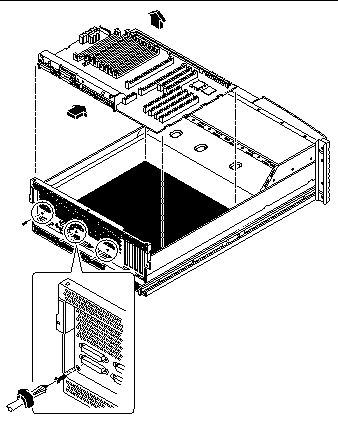
Remove the three screws securing the main logic board to the back panel.
Small arrows on the back panel point to the screws you must loosen.
-
Slide the main logic board away from the back panel until it clears the notched hold-down tabs.
-
Lift the main logic board out of the system.
-
Place the main logic board on an antistatic mat.
-
If you are replacing this main logic board, note the serial port and flash PROM jumper settings.
See "3.15 How to Set the Serial Port Jumpers" and "3.16 How to Set the Flash PROM Jumpers".
3.13.3 What Next
To replace the main logic board, complete this task:
3.14 How to Replace the Main Logic Board
3.14.1 Before You Begin
All removable components should have been removed from the old main logic board prior to removing the board from the system. You can transfer the components to the replacement board after it is installed in the system. For more information, see:
Use an antistatic mat when working with the main logic board. An antistatic mat provides the cushioning required to protect the board, to prevent the main logic board from flexing, and to provide antistatic protection.
Perform this procedure on a workbench. Sun Microsystems does not support changing the main logic board while the system is installed in a rack.
Do not attempt to install components on the main logic board while it is outside the system. Doing so can damage the main logic board.
Be sure to complete this task before starting the procedure:
3.14.2 What to Do
-
Remove the main logic board from its antistatic packaging and place it on an antistatic mat.
 Caution -
 Handle the main logic board by the back panel or edges only.
-
Set the jumper settings on the replacement main logic board so that they match the jumper settings on the original main logic board.
See "3.15 How to Set the Serial Port Jumpers" and "3.16 How to Set the Flash PROM Jumpers".
-
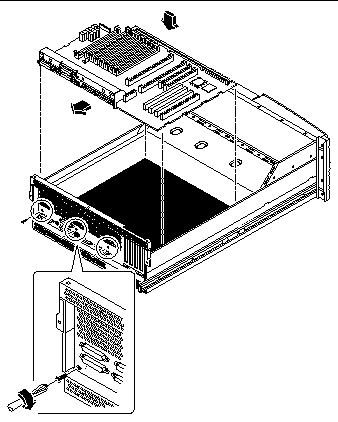
Position the replacement main logic board in the chassis.
Align the notches on the sides of the board with the corresponding tabs on the chassis.
-
Slide the main logic board toward the back of the system.
Ensure that each connector on the main logic board slides through the corresponding cutout in the chassis back panel.
-
Replace the three screws securing the main logic board to the system back panel.
-
Connect the following internal cables to the main logic board.
The connectors are keyed to connect in only one way. For information about cable connector locations, see "5.5 How to Connect the System Cables".
3.14.3 What Next
Complete these tasks to reassemble the system:
When you are ready to restart the system, be sure to run OpenBoot Diagnostics tests to verify that the system functions correctly with the parts you have just installed. For additional information, see:
You may also have to perform a reconfiguration boot so that your system is able to recognize any new parts. For additional information, see:
3.15 How to Set the Serial Port Jumpers
The serial port jumpers on the main logic board (J2604 and J2605) permit the configuration of the system's two serial ports for either EIA-432 or EIA-232D signal levels. EIA-432 levels are the default standard for North American users. EIA-232D levels are required for digital telecommunication in nations of the European Economic Community.
For further information, see your Sun Enterprise 220R Server Owner's Guide.
3.15.1 Before You Begin
Complete these tasks:
3.15.2 What to Do
-
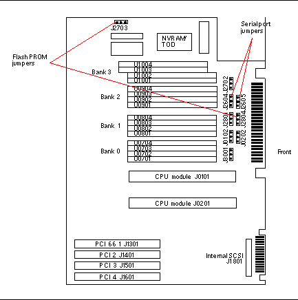
Locate the jumpers on the main logic board.
A main logic board jumper is identified by its jumper address, labeled on the board with the letter "J" followed by four numbers (JXXXX). Jumper pins are located immediately adjacent to the jumper address. On the board, pin 1 is marked with an asterisk.
-
Set the main logic board serial port jumpers J2604 and J2605.
Using long-nose pliers, place a shunt over the appropriate pins according to the following table.
Serial port jumper
A shunt on pins 1 and 2 selects
A shunt on pins 2 and 3 selects
The default shunt is on pins
J2604
RS-232D
RS-432
2 and 3
J2605
RS-232D
RS-432
2 and 3
3.15.3 What Next
Complete the following task to reassemble the system:
3.16 How to Set the Flash PROM Jumpers
The system uses flash PROMs to permit the reprogramming of specific code blocks that are held in non-volatile system memory, and to permit remote reprogramming of that code by an authorized system administrator over a local area network.
Two jumpers, J2703 and J2804, on the main logic board affect flash PROM operation. The default shunt setting of J2703 is on pins 1 and 2. Placing a shunt on pins 2 and 3 enables reprogramming of the flash PROM.
When you reprogram NVRAM, it stores the old program in the high half of NVRAM as a backup copy, in case something goes wrong in the new program. The jumper switches enable you to select which half of NVRAM you want to boot from: the low-half (or normal, default) or the high-half. This means that you can set the jumpers to select either "high-half booting" or "low-half booting."
3.16.1 Before You Begin
Complete these tasks:
3.16.2 What to Do
-
Locate the jumpers on the main logic board.
A main logic board jumper is identified by its jumper address, labeled on the board with the letter "J" followed by four numbers (JXXXX). Jumper pins are located immediately adjacent to the jumper address. On the board, pin 1 is marked with an asterisk.
For information about jumper locations, see "3.15 How to Set the Serial Port Jumpers".
-
Set the main logic board jumpers J2703 and J2804.
Using long-nose pliers, place a shunt over the appropriate pins according to the following table.
Flash PROM jumper
A shunt on pins 1 and 2 selects
A shunt on pins 2 and 3 selects
The default shunt is on pins
Signal that is controlled
J2703
Write-protect
Write-enable
1 and 2
FLASH PROM PROG ENABLE
J2804
High-half booting
Normal (low-half) booting
2 and 3
XOR LOGIC SET
3.16.3 What Next
Complete the following task to reassemble the system:
- © 2010, Oracle Corporation and/or its affiliates

