Chapter 2 Preparing to Service the System
This chapter tells you what you need to know about preparing for and completing service procedures.
Except for removing and installing disk drives, this system should be serviced by a qualified hardware service provider. Please be sure to keep the following guidelines in mind:
-
Internal disk drives and power supplies are hot-pluggable. For the servicing of any other parts internal to the system, you must first power off the system. See "2.1 How to Power Off the System".
-
Except for replacing the main logic board, which is a workbench procedure, this system is serviceable while installed in the rack. See "2.4 How to Position the System for Service".
The following tasks are covered in this chapter:
The following information is also included:
2.1 How to Power Off the System
Before turning off system power, halt the operating system as described below. Failure to halt the operating system properly can result in loss of disk drive data.
Note -
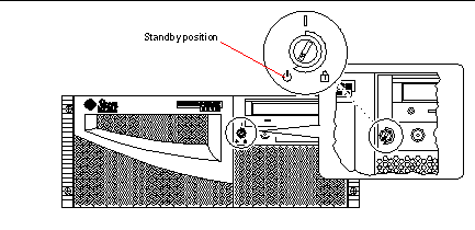
If the system "hangs" and you cannot issue an operating system command to turn the system power off, turn the keyswitch to the Standby position. This turns off power to all internal system components. For further information on keyswitch positions, see "2.9.1 Keyswitch Settings".
2.1.1 What to Do
-
Notify users that the system will be powered down.
-
Back up the system files and data, if necessary.
-
Halt the operating system using the appropriate commands.
Refer to the Solaris Handbook for Sun Peripherals that corresponds to your operating system.
-
Wait for the system halt messages and the ok prompt.
-
Turn the keyswitch on the front panel of the system to the Standby position.
2.2 How to Power On the System
2.2.1 Before You Begin
If a terminal or local console is not already connected to the system, you need to install one before continuing the startup procedure. For information, see:
Note -
Use the Reconfiguration Boot procedure instead of the power-on procedure if you have just installed an internal or external device or any new part that plugs into the main logic board except a CPU or a DIMM. See "2.3 How to Initiate a Reconfiguration Boot" for further information.
2.2.2 What to Do
Never move the system when system power is on. Movement can cause catastrophic disk drive failure. Always power off the system before moving it.
Before you power on the system, make sure that the cover is properly installed.
-
Turn on power to any peripherals and external storage devices.
Read the documentation supplied with the device for specific instructions.
-
Turn on power to the monitor or terminal.
A terminal or monitor is required for viewing system messages. For setup instructions, see "2.11 How to Attach an Alphanumeric Terminal" or "2.12 How to Configure a Local Graphics Console".
-
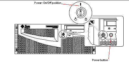
Turn the front panel keyswitch to the Power-On/Off position.
See "2.9.1 Keyswitch Settings" for information about each keyswitch setting.
-
Press the front panel Power button once.
See "2.9.1 Keyswitch Settings" for information about each keyswitch setting.
Note -The system may take anywhere from 30 seconds to two minutes before video is displayed on the system monitor or the ok prompt appears on an attached terminal. This time depends on the level of power-on self-test (POST) diagnostics being performed.
-
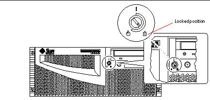
Turn the keyswitch to the Locked position.
Note -The Locked position prevents accidentally powering-off the system. See "2.9.1 Keyswitch Settings" for information about each keyswitch setting.
2.3 How to Initiate a Reconfiguration Boot
2.3.1 Before You Begin
After installing any internal or external storage device, or any new part that plugs into the main logic board, except CPU modules or DIMMs, you must perform a reconfiguration boot so that your system is able to recognize the newly installed option(s).
A terminal or a graphics console is required for viewing system messages. For information about connecting a terminal or a console, see "2.10 About Communicating With the Server" or your Sun Enterprise 220R Server Owner's Guide.
Before you power on the system, make sure that the system cover is properly installed and that the and doors are closed.
2.3.2 What to Do
-
Turn on power to any peripherals and external storage devices.
Read the documentation supplied with the device for specific instructions.
-
Turn on power to the monitor or terminal.
-
Turn the front panel keyswitch to the Power-On/Off position.
See "2.9 About the Status and Control Panel".
To run OpenBootTM Diagnostics(OBDiag) tests to verify that the system functions correctly with the new part(s) you have just installed, see "7.5 About OpenBoot Diagnostics (OBDiag)".
-
When the system banner is displayed on the terminal or console, immediately enter the Stop-a sequence on the Sun keyboard or press the Break key on the terminal keyboard.
The system banner contains the Ethernet address and host ID. To enter the Stop-a sequence, hold down the Stop key and press the a key.
Note -The system may take anywhere from 30 seconds to two minutes before the system banner appears. This time depends on the level of power-on self-test (POST) diagnostics being performed.
-
When the ok prompt is displayed, enter the following command:
ok boot -r
This command rebuilds the device trees for the system, incorporating any newly installed options. After a device has been added to a device tree, it can be recognized by the system. After the reconfiguration reboot has successfully completed, the system prompt will be displayed.
 Caution -
 Never move the system when system power is on. Movement can cause catastrophic disk drive failure. Always power off the system before moving it.
2.3.3 What Next
The system's front panel LED indicators provide power-on status information. For information about the system LEDs, see:
2.4 How to Position the System for Service
This procedure describes placing the system in position for service by sliding it out of the rack enclosure without removing it from the rack. All service procedures except removing and replacing the main logic board can be performed while the system is still attached to the rack enclosure.
Note -
Sliding the system out of the rack is not required for servicing disk drives and power supplies.
2.4.1 Before You Begin
Unless the rack is bolted to the floor, you must extend the cabinet's anti-tip legs and adjust their stabilizing feet to the floor. You must level and secure the cabinet to provide a safe working environment.
2.4.2 What to Do
-
Extend and adjust the cabinet's anti-tip legs.
-
Open (or remove) the front and back rack enclosure door(s).
-
Disconnect all external cables attached to the back panel of the system.
As you disconnect each cable, label it with a strip of masking tape indicating the cable's origin and its terminating connection.
 Caution -
 Do not disconnect the power cable(s) from the system power inlet(s) unless you are installing or replacing the power distribution board, the main logic board, or a power supply. The power cord grounds the system.
-
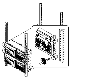
Loosen the four captive screws that secure the system to the left and right vertical rails at the front of the rack.
Use a Phillips #2 screwdriver to loosen the captive screws, which are in recessed access holes in the decorative panels affixed to the system's front panel.
-
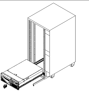
Slide the system chassis evenly out of the rack enclosure until the inner glides stop in the slide.
Grasp the system's front bezel and pull the system smoothly out of the enclosure. Continue pulling the system until the back of the chassis clears the enclosure and you hear the flat spring catches in the glides engage with an audible clicking sound. The system is then fully extended and secure.
2.4.3 What Next
For information about sliding the system into the rack enclosure, see:
2.5 How to Slide the System Into the Rack
2.5.1 Before You Begin
If you have been working inside the system, see:
2.5.2 What to Do
-
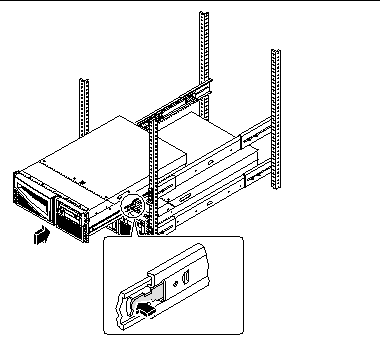
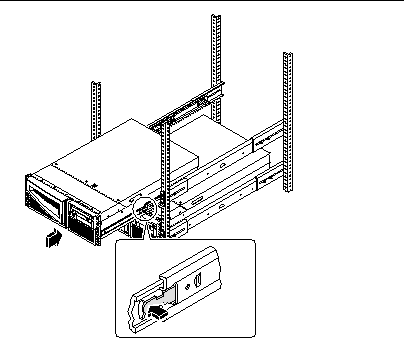
Release the two flat spring catches that lock the system into its current position.
Press in on both spring catches to free the system glides. One flat spring catch is attached to each inner glide on the system chassis, as shown in the following figure
-
Slide the system chassis evenly into the rack enclosure until the system comes to a complete stop.
-
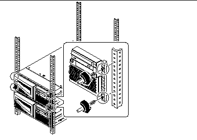
Secure the system to the left and right vertical rails at the front of the rack.
Use a Phillips #2 screwdriver to tighten the four captive screws that secure the system in the rack enclosure. These screws are in recessed access holes in the decorative panels affixed to the system's front panel.
-
Reconnect all external cables that were attached to the back panel of the system.
Examine each disconnected cable for information indicating the cable's origin and its terminating connection.
-
Replace, close, and lock the rack enclosure door(s), as appropriate.
2.5.3 What Next
To power on the system, see:
2.6 How to Remove the System Cover
Do not operate the system while the system cover is removed.
2.6.1 Before You Begin
Complete this task:
2.6.2 What to Do
-
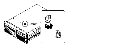
Unlock the system cover.
Use the front door key; turn the key counterclockwise to release the system cover.
-
Loosen the three captive screws securing the cover to the enclosure.
-
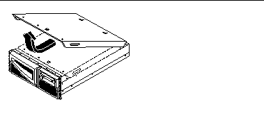
Grasp the system cover by its sides, and lift the cover upward and away from the front of the enclosure; remove the cover and set it aside.
The system cover hinges on two cutouts in the enclosure back panel. Lift the system cover away from the back of the enclosure.
2.6.3 What Next
You are now ready to install, remove, or replace components inside the system chassis.
To reassemble the system, see:
2.7 How to Replace the System Cover
2.7.1 Before You Begin
Do not operate the system while the system cover is removed.
2.7.2 What to Do
-
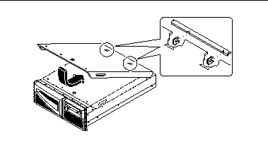
Insert the system cover into the recessed hinge cutouts on the back panel. Grasp the system cover by its sides, and lower the panel downwards and toward the front of the enclosure.
The system cover hinges on two recessed cutouts on the back panel of the enclosure.
-
Tighten the captive screws securing the panel to the enclosure.
-
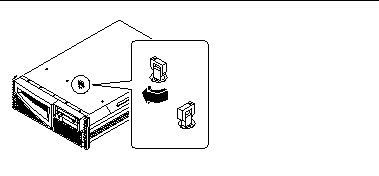
Lock the system cover.
Turn the key clockwise to engage the system cover lock.
2.7.3 What Next
To restart the system, see:
2.8 How to Avoid Electrostatic Discharge
Use the following procedure to prevent static damage whenever you are accessing any of the internal components of the system.
2.8.1 Before You Begin
Complete these tasks:
You must have the following items:
-
Antistatic wrist or foot strap
-
Antistatic mat (or the equivalent)
2.8.2 What to Do
Printed circuit boards and hard disk drives contain electronic components that are extremely sensitive to static electricity. Ordinary amounts of static from your clothes or the work environment can destroy components. Do not touch the components or any metal parts without taking proper antistatic precautions.
-
Disconnect the AC power cord from the wall power outlet only when performing the following procedures.
-
Removing and replacing the power distribution board
-
Removing and replacing the main logic board
-
Removing and installing a power supply
The AC power cord provides a discharge path for static electricity, so it should remain plugged in except when you are servicing the parts noted above.
-
-
Use an antistatic mat or similar surface.
When performing any service procedure, place static-sensitive parts, such as boards, cards, and disk drives, on an antistatic surface. The following items can be used as an antistatic surface:
-
The bag used to wrap a Sun(TM) replacement part
-
The shipping container used to package a Sun replacement part
-
Sun electrostatic discharge (ESD) mat, part number 250-1088 (available through your Sun sales representatives)
-
Disposable ESD mat, shipped with replacement parts or options
-
-
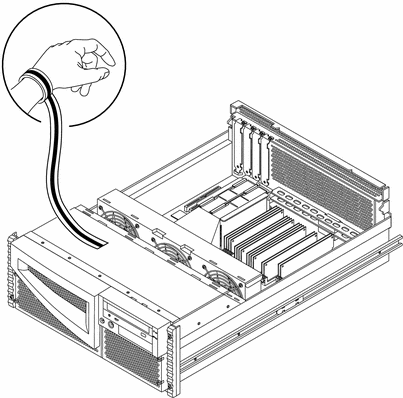
Use an antistatic wrist strap.
Attach the appropriate end to the system chassis sheet metal and attach the other end of the strap to your wrist. Refer to the instructions that come with the strap.
-
Detach both ends of the strap after you have completed the installation or service procedure.
2.8.3 What Next
To reassemble the system, see:
2.9 About the Status and Control Panel
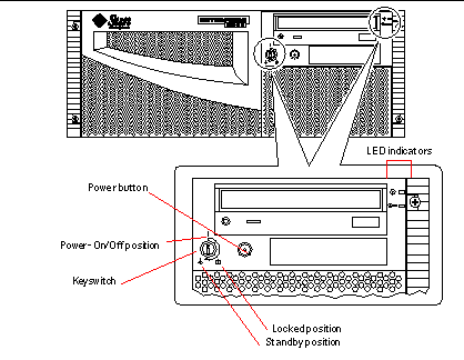
The status and control panel includes two LED indicators and a three-position security keyswitch.
2.9.1 Keyswitch Settings
The front panel keyswitch controls the power-on modes of the system. The following table describes the function of each switch setting.
|
Keyswitch Position |
Icon |
Description |
|---|---|---|
|
Power-On/Off |
This setting enables the system's Power button to turn the system power on or power off. If the system has power, holding the Power button down for five seconds while the keyswitch is in this position will cause an immediate hardware power off. |
|
|
Locked |
This setting disables the system's Power button, and also locks the front doors preventing access to the disk drives and to the power supplies. The Locked position is the recommended setting for normal day-to-day operation of the system. |
|
|
Standby |
This setting places the system in Standby mode by turning off power to all internal system components and by placing the power supplies in Standby mode. When the keyswitch is in this position, the keyboard power switch and the server's Power button are disabled. |
2.9.2 System LED Indicators
The two system LEDs consist of a system health indicator and a fault indicator. The system health indicator lights continuously green to show that the system is functioning normally. The fault indicator lights when a problem is detected in the system. Because it is important to know that a fault exists in the system, the fault indicator remains lit whether the system is in normal operating mode, or is switched to Standby mode using the keyswitch.
When you first power on the system, the LEDs individually blink on and off to verify that each one is working correctly. After that, the LEDs operate as described in the following table.
|
Name |
Icon |
Description |
|---|---|---|
|
Power-on/activity |
This green LED lights continuously when the system power is on. |
|
|
General fault |
This yellow LED lights steadily when any fault is detected (including a fault reported by a power supply LED fault). |
2.10 About Communicating With the Server
To initiate a reconfiguration boot or to diagnose problems, you need some way to enter system commands and view system output. There are three ways to do this.
-
Attach an ACSII character terminal to serial port A.
You can attach a simple terminal (or modem line) to serial port A. The terminal can be capable of displaying and entering alphanumeric but not graphical data. For instructions, see "2.11 How to Attach an Alphanumeric Terminal".
-
Establish a tip connection from another Sun system.
For information about establishing a tip connection, see your Sun Enterprise 220R Server Owner's Guide or the OpenBoot 3.x Command Reference Manual, an online version of which is included with the Solaris System Administrator AnswerBook that ships with Solaris software.
-
Install a local graphics console on your server.
The server is shipped without a mouse, keyboard, monitor, or frame buffer for the display of graphics. To install a local graphics console on a server, you must install a graphics frame buffer card into a PCI slot, and attach a monitor, mouse, and keyboard to the appropriate back panel ports. For detailed instructions, see "2.12 How to Configure a Local Graphics Console".
2.11 How to Attach an Alphanumeric Terminal
2.11.1 Before You Begin
If your server is configured without a local graphics console, you need to attach an alphanumeric (ASCII) terminal (or establish a tip connection) to the server in order to install the system software and to run diagnostic tests. For background information, see "2.10 About Communicating With the Server".
Alternatively, you can install a local graphics console on the server; see "2.12 How to Configure a Local Graphics Console".
For information about establishing a tip connection, see your Sun Enterprise 220R Server Owner's Guide or the OpenBoot 3.x Command Reference Manual, an online version of which is included with the Solaris System Administrator AnswerBook that ships with Solaris software.
2.11.2 What to Do
-
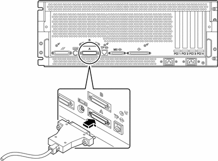
Connect the terminal's data cable to serial port A on the server's back panel.
-
Connect the terminal's power cable to an AC outlet.
-
Set the terminal to receive:
-
At 9600 baud
-
An 8-bit signal with no parity and 1 stop bit
-
See the documentation accompanying your terminal for more information.
2.11.3 What Next
You can now issue system commands from the terminal keyboard and view system messages. Continue with your service or diagnostic procedure as needed.
2.12 How to Configure a Local Graphics Console
2.12.1 Before You Begin
If your server is configured without a local graphics console, you need to install one in order to install the system and to run diagnostic tests. For background information, see "2.10 About Communicating With the Server".
Alternatively, you can attach an alphanumeric (ASCII) terminal to the system's serial port; see "2.11 How to Attach an Alphanumeric Terminal".
To install a local graphics console, you must have:
-
A supported PCI-based graphics card
-
A monitor with appropriate resolution
-
A Sun-compatible keyboard
-
A Sun-compatible mouse and mouse pad
2.12.2 What to Do
-
Install the graphics card in a vacant PCI slot.
Note -Installation must be performed by a qualified Sun service provider. For further information, see "3.4 How to Install a PCI Card".
-
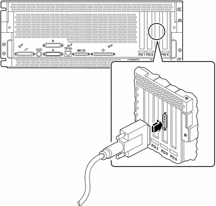
Attach the monitor video cable to the graphic card's video port.
Tighten the thumbscrews to secure the connection.
-
Connect the monitor's power cord to an appropriate AC power outlet.
-
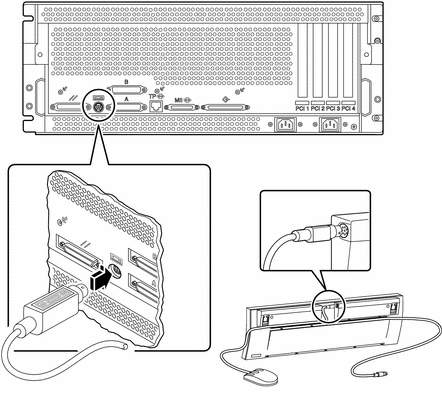
Connect the keyboard cable to the server's keyboard/mouse port.
-
Connect the mouse cable to the appropriate receptacle on the keyboard.
2.12.3 What Next
You can now issue system commands from the keyboard and view system messages. Continue with your service or diagnostic procedure as needed.
2.13 Tools Required for Installation and Service
The following tools are required to install and service the system:
-
Screwdriver, Phillips #1
-
Screwdriver, Phillips #2
-
Screwdriver, long flat-blade #2
-
Needle-nose pliers
-
Wrench, 5/16ths inch
-
Wrench, 1/2 inch
-
Electrostatic discharge mat, Sun part number 250-1088, or equivalent
-
Grounding wrist or foot strap
The latter two items help protect the server against damage due to electrostatic discharge. For more information, see "2.8 How to Avoid Electrostatic Discharge".
2.14 How to Remove the System From the Rack
You must remove the system from the rack when removing and replacing the main logic board. You can perform all other procedures while the system is still attached to the rails extended from the rack. If you want to remove the system from the rack for any other reason, follow the instructions in this section.
Unless the rack is bolted to the floor, you must extend the cabinet's anti-tip legs and adjust their stabilizing feet to the floor. Level and secure the cabinet to provide a safe working environment.
The chassis is heavy. Two people are required to remove the system from the rack enclosure in the following procedure.

2.14.1 Before You Begin
Complete these tasks:
-
Identify a helper to assist you in removing the system
Discuss the task and verify that your helper can safely lift and carry 34 lbs (17 kg), which is approximately half the weight of a fully-equipped system.
Review the steps in the next section with your helper beforehand and discuss how to coordinate your efforts to ensure your mutual safety.
When completing a two-person procedure, always communicate your intentions clearly before, during, and after each step to minimize confusion.
2.14.2 What to Do
-
Position one person on each side of the system, facing the system glides.
When you are both in position, verify that your helper understands what to do with the system after you remove it. Also agree on a route to follow, and visually inspect it for potential safety hazards (for example, cables on the floor, other people working in the vicinity, and so on).
-
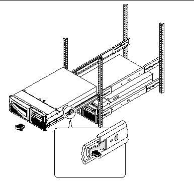
Locate the flat spring catches on the inner glides.
Each person should visually locate one of the two flat spring catches that release the system from the rack glide. One catch is attached to each inner glide, as shown in the following figure.
-
Prepare to remove the system.
Each person should place one hand on the flat spring catch and their other hand beneath the chassis, palm up, ready to support the weight of the chassis.
-
Simultaneously press in on both flat spring catches and slide the system out of the glides.
Each person presses one spring catch and helps slide the system free of the outer glide, supporting the weight of the system as it slides free of the glides.
-
Set the system on a workbench or other stable surface.
-
Slide the empty rack slides back into their protective outer glides.
-
Reattach, close, and lock the rack doors as appropriate.
2.14.3 What Next
For information about placing the system into the rack glides, see:
2.15 How to Place the System Into the Rack Glides
This procedure assumes that the slide assembly is already installed in the rack. For further information on assembling the slide assemblies and rack enclosures, see the Sun Enterprise 220R Server Setup and Rackmounting Guide.
The chassis is heavy. Two people are required to place the system into the rack enclosure glides in the following procedure.

2.15.1 Before You Begin
Complete the following tasks:
-
Identify a helper to assist you in removing the system.
-
Verify that your helper can safely lift and carry 34 lbs (17 kg), which is approximately half the weight of a fully-equipped system.
-
Assemble the correct tools for the procedure. See "2.13 Tools Required for Installation and Service".
-
Open (and remove) the rack enclosure front door.
When completing a two-person procedure, always communicate your intentions clearly before, during, and after each step to minimize confusion.
2.15.2 What to Do
-
Extend the cabinet's anti-tip legs.
 Caution -
 Unless the rack is bolted to the floor, you must extend the cabinet's anti-tip legs and adjust the stabilizing feet to the floor.
-
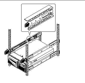
Push the runner on each slide assembly as far back as possible into the slide assembly.
-
Push in the inner rail on each slide assembly until it reaches the stops that are located furthest away from the front of the rack.
-
Push in the runner until it stops in the slide assembly.
-
-
Position one person on each side of the system, facing the inner glides on the system chassis.
When you are both in position, verify that your helper understands what to do with the system after you lift it. Also agree on a route to follow to the rack enclosure, and visually inspect the route for potential safety hazards (for example, cables on the floor, other people working in the vicinity, and so on).
-
Lift the system.
Each person should place both hands beneath the chassis and support half the weight of the system.
-
Carry the system from its location to the front of the rack enclosure.
-
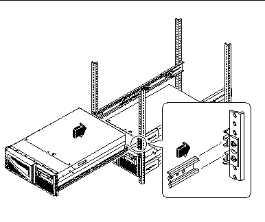
Insert the system glides into the inner slides of the rack glides.
Verify that the empty rack slides are completely inside their protective outer glides. Slide the crimped end of each system glide into the corresponding inner slide within the rack glide.
-
Slide the system smoothly into the rack until the flat spring catches stop the system.
-
Simultaneously press in on both flat spring catches and finish sliding the system completely into the rack.
-
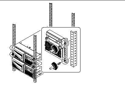
Tighten the four captive screws securing the system to the left and right vertical rails at the front of the rack.
Use a Phillips #2 screwdriver to tighten the captive screws, which are in recessed access holes in the filler panels affixed to the system's front panel.
-
Reconnect every external cable previously attached to the back panel of the system.
As you reconnect each cable, check it for information indicating the cable's origin and its terminating connection.
-
Reattach, close, and lock the rack door(s) as appropriate.
2.15.3 What Next
To power on the system, see:
- © 2010, Oracle Corporation and/or its affiliates
