5.4.2 What to Do
-
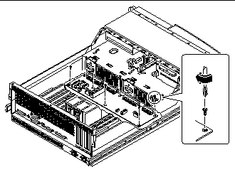
Position the power distribution board in the chassis floor.
You may need to adjust the cable attached to the center AC power connector assembly so that it does not interfere with the positioning of the power distribution board.
-
Replace the seven Phillips screws that secure the board to the chassis.

-
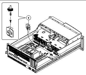
Replace the AC power connector assembly (and the cable attached to it).
Use a Phillips #2 screwdriver.

-
Replace the power distribution board cover panel.
-
Position the cover in place over the system chassis.
Hold the cover at an approximately 30-degree angle from the chassis, aligning the slots on the cover with the tabs on the main logic board mounting plate.
-
Lower the cover into place.
Make sure you insert the tabs on the cover into the slots on the main logic board mounting plate.

-
-
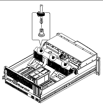
Tighten the three captive Phillips screws that secure the power distribution board cover panel to the system chassis.
-
Connect the CPU core voltage power cable to the power distribution board at connector J0202.
For information about cable connector locations, see "5.5 How to Connect the System Cables". Connectors are keyed and attach in only one way.
-
Connect the CPU core voltage power sense cable to the power distribution board at connector J0203.
-
Connect the main power cable to the power distribution board at connectors J0201 and J0207.
-
Connect the CPU power sense cable to the power distribution board at connectors J0205 and J0206.
-
Connect the keyswitch/power button/LED cable to the power distribution board at connector J0500.
-
Connect the I/O power cable to the power distribution board at connector J0210.
-
Connect the UltraSCSI data cable to the main logic board at connector J1801.
- © 2010, Oracle Corporation and/or its affiliates
