Chapter 5 Removing and Replacing Backplanes and Cables
This chapter describes how to remove and replace backplanes and cables within the system. For a list of part numbers for field-replaceable units and optional equipment, see Appendix D, Illustrated Parts Breakdown.
The following tasks are covered in this chapter:
5.1 How to Remove the UltraSCSI Backplane
5.1.1 Before You Begin
Complete these tasks:
Note -
You must remove all disk drives from the disk cage assembly. Be sure to note the disk slot number associated with each drive. Later, when you reinstall the disk drives, it is important to return each drive to its original location.
5.1.2 What to Do
-
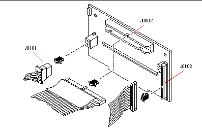
Disconnect the I/O power cable from the UltraSCSI backplane at connector J0101.
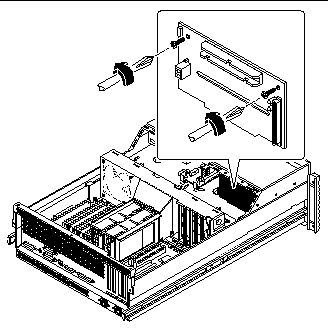
See Step 4 for the location of the UltraSCSI backplane in the system.
-
Disconnect the UltraSCSI data cable from the UltraSCSI backplane at connector J0102.
Press the levers on the sides of the backplane connector.
-
Disconnect the removable media SCSI cable from the UltraSCSI backplane at connector J0302.
-
Remove the two Phillips screws that secure the UltraSCSI backplane to the chassis.
-
Remove the backplane from the chassis.
Place the backplane on an antistatic mat.
5.1.3 What Next
To replace the UltraSCSI backplane, complete this task:
5.2 How to Replace the UltraSCSI Backplane
5.2.1 Before You Begin
Complete this task:
5.2.2 What to Do
-
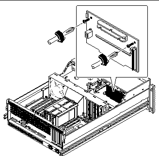
Position the UltraSCSI backplane in place behind the disk drive bay in the chassis.
-
Replace the two Phillips screws that secure the UltraSCSI backplane to the chassis.
-
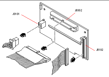
Connect the UltraSCSI data cable from the main logic board to connector J0102 on the UltraSCSI backplane.
The connector is keyed to attach in only one way.
-
Connect the removable media assembly SCSI cable to connector J0302 on the UltraSCSI backplane.
The connector is keyed to attach in only one way.
-
Connect the I/O power cable to connector J0101 on the UltraSCSI backplane.
The connector is keyed to attach in only one way.
5.2.3 What Next
To reassemble the system, complete these tasks:
5.3 How to Remove the Power Distribution Board
5.3.1 Before You Begin
Complete these tasks:
Unplug the AC power cord(s) from the back of the system before performing this procedure. Attempting to remove the power distribution board while the AC power cord is plugged into a power source can result in serious personal injury.
Note -
You need to remove the system power supplies before attempting to remove the power distribution board.
5.3.2 What to Do
-
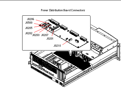
Disconnect the CPU core voltage power cable and the CPU core voltage power sense cable from the power distribution board at connectors J0202 and J0203.
For information about cable connector locations, see "5.5 How to Connect the System Cables".
-
Disconnect the UltraSCSI data cable from the main logic board at connector J1801.
-
Disconnect the I/O power cable from the power distribution board at connector J0210.
-
Disconnect the main power cable from the power distribution board at connectors J0201 and J0207.
-
Disconnect the CPU power sense cable from the power distribution board at connectors J0205 and J0206.
-
Disconnect the keyswitch/power button/LED cable from the power distribution board at connector J0500.
-
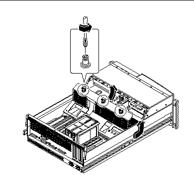
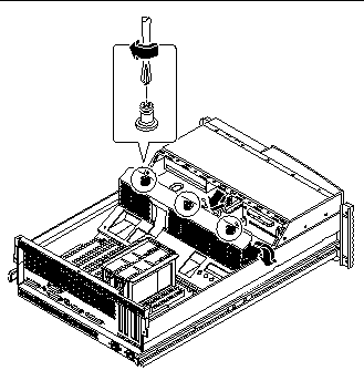
Loosen the three captive Phillips screws that secure the power distribution board cover panel to the chassis.
-
Remove the power distribution board cover panel.
-
Tilt the panel toward the back of the system approximately 30 degrees.
Hold the cover panel by the edge nearest the chassis front.
-
Gently pull the cover panel forward and up, out of the system.
Set the power distribution cover panel aside.
 Caution -
 Be sure that the AC power cord(s) has been disconnected from the system before continuing. Attempting to remove the power distribution board while the AC power cord is plugged into a power source can result in serious personal injury.
-
-
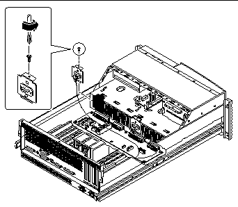
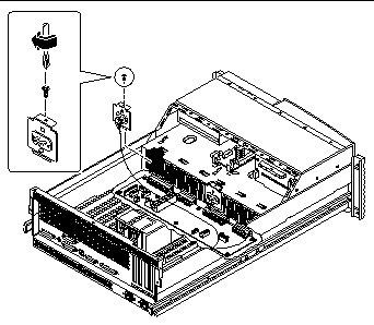
Remove the left (when looking from the back of the system) AC power connector assembly from the chassis.
Keep the cable attached to the connector assembly. Use a Phillips #2 screwdriver to remove the screw. Set the end of the cable aside in the back of the system so that the cable doesn't interfere with lifting the power distribution board out of the chassis.
-
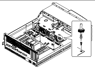
Remove the seven screws securing the power distribution board to the chassis.
-
Adjust the cable connected to the center AC power connector assembly so that it doesn't interfere with lifting the power distribution board out of the chassis.
-
Lift the power distribution board out of the chassis.
Place it on an antistatic mat.
5.3.3 What Next
To replace the power distribution board, complete this task:
5.4 How to Replace the Power Distribution Board
5.4.1 Before You Begin
Complete this task:
Be sure that the AC power cord(s) is disconnected from the back of the system before performing this procedure. Attempting to replace the power distribution board while the AC power cord is plugged into a power source can result in serious personal injury.
5.4.2 What to Do
-
Position the power distribution board in the chassis floor.
You may need to adjust the cable attached to the center AC power connector assembly so that it does not interfere with the positioning of the power distribution board.
-
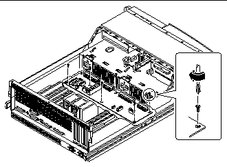
Replace the seven Phillips screws that secure the board to the chassis.
-
Replace the AC power connector assembly (and the cable attached to it).
Use a Phillips #2 screwdriver.
-
Replace the power distribution board cover panel.
-
Position the cover in place over the system chassis.
Hold the cover at an approximately 30-degree angle from the chassis, aligning the slots on the cover with the tabs on the main logic board mounting plate.
-
Lower the cover into place.
Make sure you insert the tabs on the cover into the slots on the main logic board mounting plate.
-
-
Tighten the three captive Phillips screws that secure the power distribution board cover panel to the system chassis.
-
Connect the CPU core voltage power cable to the power distribution board at connector J0202.
For information about cable connector locations, see "5.5 How to Connect the System Cables". Connectors are keyed and attach in only one way.
-
Connect the CPU core voltage power sense cable to the power distribution board at connector J0203.
-
Connect the main power cable to the power distribution board at connectors J0201 and J0207.
-
Connect the CPU power sense cable to the power distribution board at connectors J0205 and J0206.
-
Connect the keyswitch/power button/LED cable to the power distribution board at connector J0500.
-
Connect the I/O power cable to the power distribution board at connector J0210.
-
Connect the UltraSCSI data cable to the main logic board at connector J1801.
5.4.3 What Next
To reassemble the system, complete this task:
5.5 How to Connect the System Cables
This section provides an overview of cable connector locations and cable routing. Procedures for removing and replacing specific cables are covered within the removal and replacement process of the assemblies with which these cables are associated.
5.5.1 Before You Begin
Complete these tasks:
5.5.2 What to Do
-
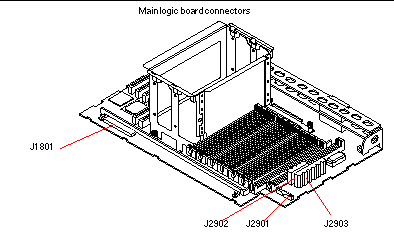
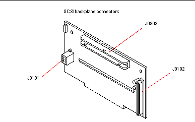
Identify the cable that you want to install or replace. Use the information in the following table and illustrations to determine where to connect each end of the cable.
-
Install the cable according to the routing and cable management instructions provided in the table.
Each cable connector is keyed so that it can be connected in only one way.
5.5.3 Cable Connectors and Routing
|
Cable Name |
Connections |
Routing and Management |
|---|---|---|
|
CPU power sense cable |
From: Power distribution board (J0205) and (J0206)To: Main logic board (J2901) |
Routed from under the fan tray assembly to the main logic board |
|
Main power cable |
From: Power distribution board (J0201) and (J0207)To: Main logic board (J2902) and (J2903) |
Routed from under the fan tray assembly to the main logic board |
|
I/O power cable |
From: Power distribution board (J0210)To: UltraSCSI backplane (J0101) andTo: Removable media assembly power connector |
Routed from under the fan tray assembly, through the notch on the fan tray assembly to the UltraSCSI backplane and the RMA power connector |
|
UltraSCSI data cable |
From: Main logic board (J1801)To: UltraSCSI backplane (J0102) |
Routed flat under the tab on the side of the fan tray assembly |
|
Removable media SCSI cable |
From: UltraSCSI backplane (J0302)To: RMA SCSI Connector |
Routed from the UltraSCSI backplane to the removable media assembly SCSI connector |
|
Keyswitch/power button/LED cable |
From: Power distribution board (J0500)To: Front of chassis |
Routed under the notch on the fan tray assembly |
|
CPU core voltage power cable |
From: Power distribution board (J0202)To: DC-to-DC board (J0103) |
Routed from the power distribution board to the DC-to-DC board |
|
CPU core voltage power sense cable |
From: Power distribution board (J0203)To: DC-to-DC board (J0102) |
From the power distribution board to the DC-to-DC board |
5.5.4 What Next
To replace a cable, complete this task:
- © 2010, Oracle Corporation and/or its affiliates
