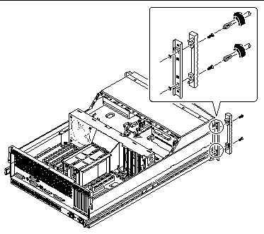
Chapter 6 Removing and Replacing Miscellaneous Assemblies
This chapter describes how to remove and replace the miscellaneous assemblies within the system. For a list of part numbers for field-replaceable units and optional equipment, see Appendix D, Illustrated Parts Breakdown.
The following tasks are covered in this chapter:
6.1 How to Remove a Power Supply
6.1.1 Before You Begin
It is not necessary to power off the system if you are removing a redundant power supply. For more information, see "About Power Supplies" in your Sun Enterprise 220R Server Owner's Guide.
If your system has only one power supply, complete this task:
6.1.2 What to Do
-
Identify the power supply that you want to remove.
-
Unlock the system doors and swing them open.
Turn the keyswitch to the Power-On/Off position. This unlocks the system front access doors.
-
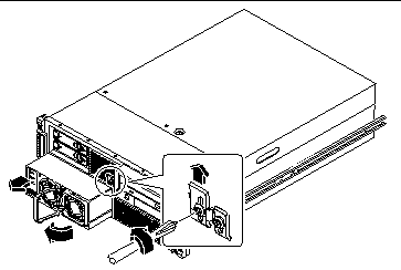
Loosen the Phillips screw that secures the power supply retaining clip until you can push the clip upward.
-
Using your thumb, push up the retaining clip until it clears the power supply.
 Caution -
 Keep the thumb holding the retainer clip up clear of the power supply as you slide it out from its bay.
-
With your other hand, rotate the power supply handle so that it is perpendicular to the front face of the unit.
-
Pull out the power supply in a smooth motion until the unit is free of the bay.
Note -When removing a hot-pluggable power supply, do not disengage and reengage the supply in rapid succession.
-
If you have removed a redundant power supply and are not replacing it immediately, install a power supply filler panel.
The filler panel maintains proper system cooling and prevents electromagnetic interference. Align the filler panel over the empty bay and push it into place.
-
Tighten the Phillips screw on the power supply retaining clip.
6.1.3 What Next
To replace a power supply, complete this task:
6.2 How to Install a Power Supply
6.2.1 Before You Begin
If you are installing a redundant power supply, it is not necessary to power off the system. For more information, see "About Power Supplies" in your Sun Enterprise 220R Server Owner's Guide.
6.2.2 What to Do
-
Unlock the system doors and swing them open.
Turn the keyswitch to the Power-On/Off position. This unlocks the system front access doors.
-
Loosen the Phillips screw that secures the power supply retaining clip until you can push the clip upward.
-
If you are upgrading your system with an additional power supply, remove the filler panel covering the power supply bay.
-
With one hand, push up the retaining clip until it clears the filler panel.
-
Partially pry the top of the filler panel out of the bay, using a flat-blade screwdriver.
-
Lift the filler panel out and away from the bay, and set it aside.
-
Keep the filler panel in case you need to remove the power supply later.
The filler panel maintains proper system cooling and prevents electromagnetic interference in the absence of a second power supply.
-
-
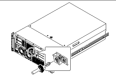
Using your thumb, push up the retaining clip until there is enough clearance to slide the power supply into its bay.
-
With your other hand, align the new power supply with its bay.
-
Slide the new power supply into the power supply bay until the power supply connectors start to engage the connectors on the power distribution board.
 Caution -
 Be sure to keep the thumb holding up the retainer clip out of the way as you slide the power supply into its bay.
When the back of the power supply has cleared the retainer clip and is in the bay, release the clip.
-
Push on the front of the power supply firmly to engage the connectors with the power distribution board.
 Caution -
 If you are hot-plugging a redundant supply, take care to avoid jarring or shocking the system.
-
Tighten the Phillips screw on the power supply retaining clip.
Note -As you tighten the screw, the lower end of the retaining clip presses on the front of the power supply. Fully tightening the Phillips screw ensures that the power supply is properly seated in its bay.
6.2.3 What Next
Verify correct operation of the power supply by checking the fan and LED indicators on the power supply. You should hear the fan start spinning and two green LEDs should light within three seconds of completing a hot-plug installation (or after restoring power to the system).
For more information about the power supply LEDs, see:
6.3 How to Remove the Fan Tray Assembly
6.3.1 Before You Begin
Complete these tasks:
6.3.2 What to Do
-
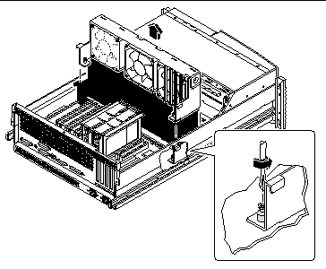
Loosen the two captive Phillips screws securing the fan tray assembly to the chassis.
-
Lift the fan tray assembly out of the system chassis.
6.3.3 What Next
To replace the fan tray assembly, complete this task:
6.4 How to Replace the Fan Tray Assembly
6.4.1 Before You Begin
Complete this task:
6.4.2 What to Do
-
Position the fan tray approximately 2 inches (5 centimeters) over its final location in the system chassis.
-
Route the UltraSCSI disk data cable flat under the tab on the side of the fan tray assembly.
-
Route the main power and keyswitch/power button/LED cables under the right notch on the fan tray assembly.
For information about cable locations, see "5.5 How to Connect the System Cables".
-
Route the I/O power cableunder the left notch on the fan tray assembly.
-
Lower the fan tray into place in the system chassis.
Align the tabs on the fan tray assembly with the notches on the chassis. Make sure that you keep the UltraSCSI data cable flat against the side of the fan tray assembly.
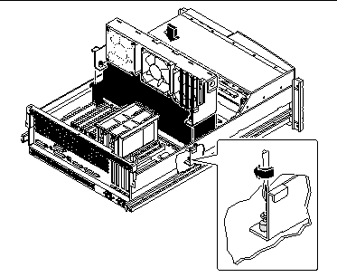
Note -As you lower the fan tray assembly, ensure that the cables remain properly routed under their notches on the fan tray assembly.
-
Tighten the two captive Phillips screws securing the fan tray assembly to the chassis.
6.4.3 What Next
To reassemble the system, complete this task:
6.5 How to Remove the DC-to-DC Converter
6.5.1 Before You Begin
Complete these tasks:
6.5.2 What to Do
-
Disconnect the AC power cord(s) from the system.
-
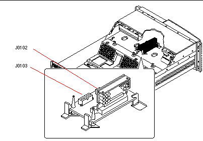
Disconnect the CPU core voltage power cable from connector J0103 on the DC-to-DC converter board.
Press the tab on the connector.
-
Disconnect the CPU core voltage power sense cable from connector J0102 on the DC-to-DC converter board.
-
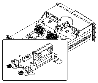
Unclip the DC-to-DC converter board from the plastic retaining clips.
Push down on the plastic tabs while carefully lifting the end of the DC-to-DC converter board.
-
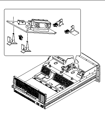
Remove the DC-to-DC converter from the chassis.
Lift the DC-to-DC converter board off the plastic retaining posts while carefully pulling the board back and out from the metal tabs in the chassis.
6.5.3 What Next
Complete the following task to reassemble the system:
Note -
The DC-to-DC converter on this system is an assembly consisting of two parts, part numbers 375-0094 and 300-1455. Be sure to order both parts if you need to replace the DC-to-DC converter.
6.6 How to Replace the DC-to-DC Converter
6.6.1 Before You Begin
Complete this task:
Note -
The DC-to-DC converter on this system is an assembly consisting of two parts, part numbers 375-0094 and 300-1455. Be sure you have both parts when your are replacing the DC-to-DC converter.
6.6.2 What to Do
-
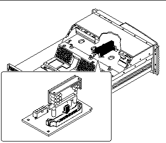
Insert the replacement VRM DC-to-DC card into the replacement DC-to-DC converter board.
-
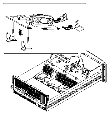
Insert the cutout end of the DC-to-DC converter board into the slots on the metal tabs in the chassis.
Insert the DC-to-DC board into the metal slots at an angle so that the post holes on the back of the converter board align with the plastic retaining clip posts.
-
Lower the DC-to-DC converter onto the plastic retaining clips.
Ensure that the other end of the DC-to-DC converter board remains in place in the metal tabs.
-
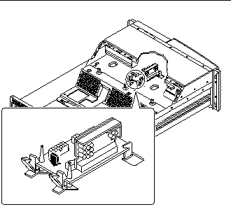
Secure the DC-to-DC converter board in place.
Push down on the board until the plastic tabs secure the board in place.
-
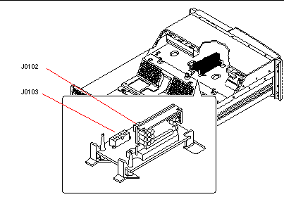
Connect the CPU core voltage power cable to connector J0103 on the DC-to-DC converter board.
The connector is keyed so that it installs in only one way.
-
Connect the CPU core voltage power sense cable to connector J0102 on the DC-to-DC converter board.
The connector is keyed so that it installs in only one way.
6.6.3 What Next
Complete this task to reassemble the system:
6.7 How to Remove the Keyswitch/Power Button/LED Cable
6.7.1 Before You Begin
Complete these tasks:
6.7.2 What to Do
-
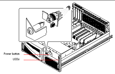
Pull the keyswitch cable assembly from the back of the keyswitch assembly.
Gently twist the cable assembly back and forth while pulling it away from the keyswitch.
-
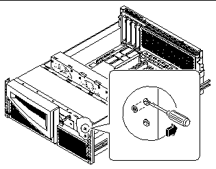
Remove the 3/16ths-inch nut from the front of the Power button.
-
Remove the LEDs and their cables from the system.
-
Using a flat-blade screwdriver, gently pull the plastic friction fit collars securing the LEDs from the chassis.
-
Gently push the LED's through their cutouts in the chassis.
-
-
Pull the keyswitch/power button/LED cable out the back of the system.
-
Disconnect the keyswitch/power button/LED cable from connector J0500 on the power distribution board.
6.7.3 What Next
To replace the keyswitch/power button/LED cable, complete this task:
6.8 How to Replace the Keyswitch/Power Button/LED Cable
6.8.1 Before You Begin
Complete this task:
6.8.2 What to Do
-
Route the keyswitch and power on-off cables to their positions in the front of the chassis.Attach the keyswitch cable to the keyswitch assembly.
-
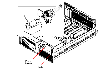
Align the post on the keyswitch with the socket in the connector.
-
Gently insert the keyswitch into the connector.
-
Rotate the keyswitch in the connector until the tabs on the keyswitch snap into place.
The long tab on the keyswitch should lock into the corresponding groove on the cable connector when the keyswitch is properly seated in the connector.
-
-
Position the Power button in the chassis.
-
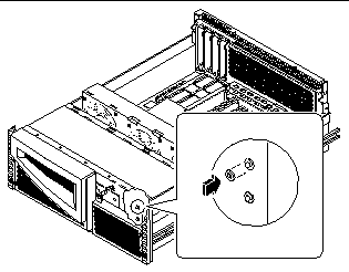
Replace the 3/16ths-inch nut on the front of the Power button.
-
Insert the plastic LED friction-fit collars into their cutouts on the chassis.
-
Insert the LEDs into their friction fit collars on the chassis.
The green LED goes in the top collar. The yellow LED goes in the bottom collar.
-
Connect the keyswitch/power button/LED cable to connector J0500 on the power distribution board.
6.8.3 What Next
To reassemble the system, complete these tasks:
6.9 How to Remove a System Door
6.9.1 Before You Begin
Complete these tasks:
6.9.2 What to Do
-
Unlock the system doors.
-
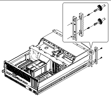
Remove the decorative panel from the flange of the system chassis.
-
Remove the washers from the screws securing the decorative panel to the chassis flange.
The washers are on the captive screws that attach the system to the rack rails.
-
Pull the decorative panel off the chassis flange.
-
-
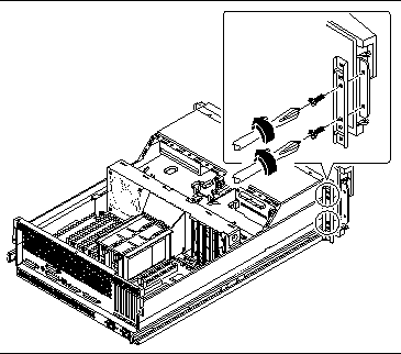
Unscrew the hinge from the chassis flange.
Use a Phillips #2 screwdriver.
6.9.3 What Next
To replace a door, complete this task:
6.10 How to Replace a System Door
6.10.1 What to Do
-
Position the door hinge on the chassis flange.
The hinge goes on the front of the chassis flange.
-
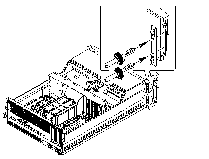
Replace the two hinge screws securing the hinge to the chassis flange.
Use a Phillips #2 screwdriver.
-
Replace the decorative panel on the chassis flange.
-
Close and lock the system doors.
6.10.2 What Next
To reassemble the system, complete this task:
- © 2010, Oracle Corporation and/or its affiliates

