


Chapter 2
Rack Installation
This chapter provides step-by-step instructions for rackmounting the server into a Sun expansion cabinet or other EIA-compliant rack enclosure.
To rackmount a Sun Enterprise 420R server, complete the following tasks in the order listed:
The Sun Enterprise 420R Server Rackmounting Overview included with your documentation set illustrates the rackmounting steps in a convenient, graphical overview. This chapter provides detailed information about each step.
- Phillips #2 screwdriver
- Flat-blade screwdriver
- Set of Allen wrenches to remove the side panels on some rack enclosures
- An adjustable wrench to tighten the nuts on the mounting brackets
- Unpack the system and verify the contents. See Chapter 1 for instructions.
- Unpack the accessory box and place the slide assemblies, mounting brackets, and hardware on a clear surface.
- Verify that you have the components and hardware shown in Accessory Box Contents.
- Read the rack enclosure requirements described in Appendix A of this guide.
- Read the Safety Precautions that follow.
For a complete description of the safety precautions to follow when installing a Sun Enterprise 420R server, see the Sun Enterprise 420R Server Owner's Guide.
 Caution -
Install the system as low as possible into the rack enclosure. For best stability, do not install the system above equipment that weighs less than it does.
Caution -
Install the system as low as possible into the rack enclosure. For best stability, do not install the system above equipment that weighs less than it does.
Caution -
The system is heavy. In the following procedures, two people are required to move the system. Two people are also required to align and install the slide assemblies into the rack.

 Caution - l
For proper ventilation, each system in the rack enclosure requires 28 square inches (181 square cm) of unrestricted airflow into the front of the system, and 23 square inches (148 square cm) of unrestricted exhaust port at the back of the system. Maintain a minimum 1.5 inches (3.8 cm) clearance between the system and any front or back doors. See Appendix A for more information.
Caution - l
For proper ventilation, each system in the rack enclosure requires 28 square inches (181 square cm) of unrestricted airflow into the front of the system, and 23 square inches (148 square cm) of unrestricted exhaust port at the back of the system. Maintain a minimum 1.5 inches (3.8 cm) clearance between the system and any front or back doors. See Appendix A for more information.
- Open and remove (if applicable) the front and back doors of the rack enclosure.
- See the instructions provided with your rack enclosure.
- Stabilize the rack enclosure by extending its anti-tip legs or bolting the rack securely to the floor.
- See the instructions provided with your rack enclosure.
- Remove the side panels from the rack enclosure, if applicable.
- See the instructions provided with your rack enclosure. Removing the side panels can improve access to the nuts and screws that are installed when securing the system in the rack enclosure.
Attach a short and a long mounting bracket to the outside of each slide assembly.
Repeat these steps for each slide assembly.
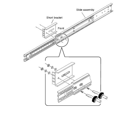
- Attach a short mounting bracket to the front of each slide assembly.
- Extend the slide assembly to expose the holes for the front mounting bracket.
- Release the coil spring catch on the inner rail to extend the slide assembly.
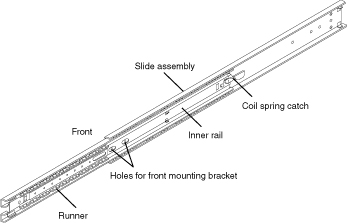
- Position a short bracket over the front end of the slide assembly.
- The lip of the bracket should face the front of the slide assembly, as shown.
- Secure the short bracket to the slide assembly. Use two 8-32 panhead screws with a flat washer, a lock washer, and a nut for each screw.
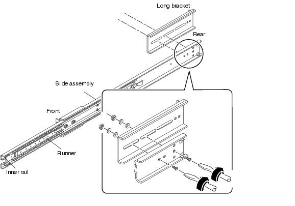
- Attach a long mounting bracket to the rear end of each slide assembly.
- Position the long bracket over the rear end of the slide assembly.
- Align the elongated slots at the end of the long bracket over the holes on the slide assembly, as shown.
- Secure the long bracket loosely to the slide assembly. Use two 8-32 panhead screws, flat washers, lock washers, and nuts for each long bracket.
- Do not tighten the screws completely. You may need to adjust the mounting bracket when you install the slide assembly into the rack enclosure.
- Push in the inner rail and runner on each slide assembly.
- Push the inner rail all the way into the slide assembly. If necessary, release the coil spring catch.
- Push in the runner until it stops.
- Locate and mark the correct positions on the rack's vertical mounting rails to install the slide assemblies.
- Allow four rack unit spaces (7.0 inches/17.78 cm) or 12 holes per server. Because the holes on a standard rack enclosure are arranged in sets of 3 holes spaced 5/8ths, 5/8ths, 4/8ths of an inch apart, determining which holes to use for attaching a slide assembly depends on exactly where you locate the system.
You can either count the holes so that each slide assembly is installed at the same height front-to-back and side-to-side in the rack or use the Rack Buddy included with your system documentation. Mark the location on the rack enclosure with a felt tip marker or masking tape.
- Install the slide assemblies into the lowest available position. If this is the first system you are installing into the rack, use holes 3 and 4 or 5. Install additional servers from the base up.
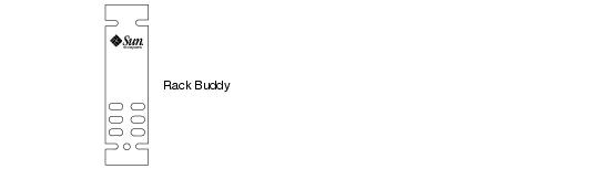
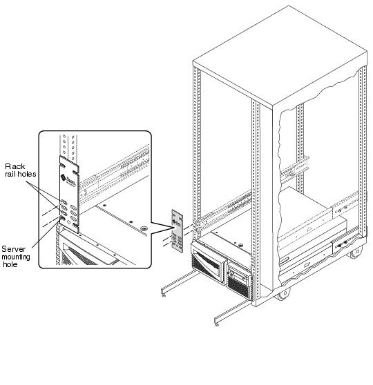
To use the Rack Buddy, complete these steps:
- Place the Rack Buddy over the left front vertical rack rail. See the next figure.
- Move the bottom of the Rack Buddy to the exact location on the rack rail where the bottom of the system will be located.
- Adjust the Rack Buddy so that the bottom server screw mounting location is centered on the space in the Rack Buddy.
- Looking through the three glide holes on the Rack Buddy, locate the two rack rail holes that are most visible through the Rack Buddy and mark them.
- Use these two rack rail holes to attach the slide assembly to the rack rail. You will only use two of the three holes to attach the slide assembly. The assembly bracket has three holes to allow for the differences in spacing between the rack rail holes. Mark the corresponding holes on the right front vertical rack rail.
-
- Attach one slide assembly to the right rack mounting rail, and the other slide assembly to the left rack mounting rail. See the next figure.
- With the help of an assistant, position the slide assembly on the inside of the rack enclosure with the short mounting bracket facing the front of the rack.
- Count the holes so that each slide assembly is installed at the same height front-to-back and side-to-side in the rack or use the Rack Buddy as described in Step 1.
- Attach the front short mounting bracket of one slide assembly to the front rail on the rack.
- Secure the slide bracket assembly to the front mounting rail using two Phillips 10-32 panhead screws. Use the holes you marked in Step 1. Finger-tighten the screws. Do not tighten the screws completely until all the screws are in place and the slide assemblies are level.
- Attach the long mounting bracket of the same slide assembly to the back rail of the rack.
- Secure the slide bracket assembly to the back mounting rail using two Phillips 10-32 panhead screws. Finger-tighten the screws. Do not tighten the screws completely until all the screws are in place and the slide assemblies are level.
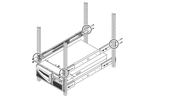
Note - You may need to slide the rear mounting bracket forward or backward on the slide assembly to accommodate the depth of the rack.
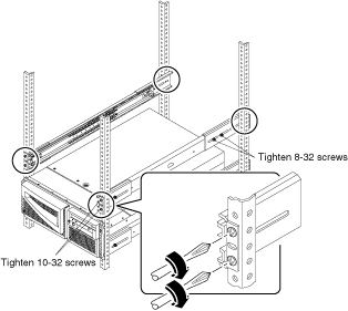
- Completely tighten all of the rackmounting screws.
- Make sure that the slide assemblies are level front-to-back and left-to-right.
- Tighten the eight 10-32 screws that secure the slide assemblies to the vertical rack rails.
- Tighten the four 8-32 screws that secure the long mounting brackets to the slide assemblies.
-
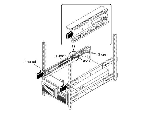
- Verify that the runner on each slide assembly is pushed as far back as possible into the slide assembly, as shown.
- Push in the inner rail on each slide assembly until it reaches the stops that are located furthest away from the front of the rack.
- Push in the runner until it stops in the slide assembly.
- Lift the server (one person on each side of the server) and approach the rack enclosure with the back of the server facing the rack enclosure.
 Caution -
The system is heavy. Two people are required to move the system.
Caution -
The system is heavy. Two people are required to move the system.
-

- Align the crimped end of the inner glides on the server with the slide bracket assemblies in the rack enclosure.
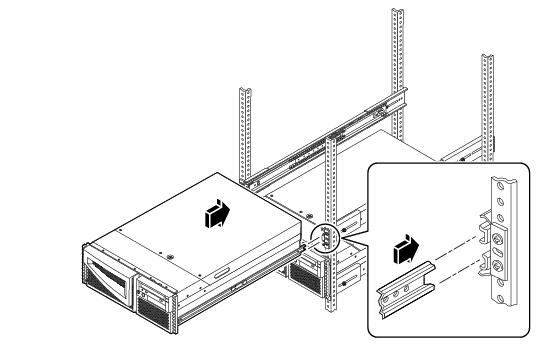
-
- Slide the server evenly into the rack enclosure until the inner glides stop in the slide.
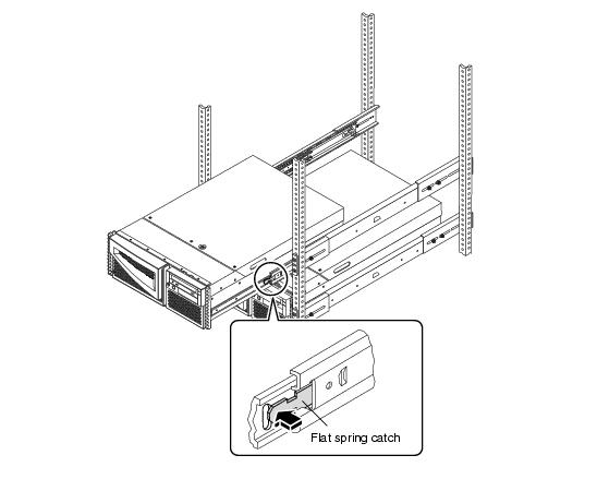
- On each side of the chassis, push in the flat spring catch on each inner glide and push the server all the way into the rack.
-
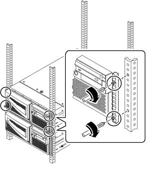
- Secure the chassis to the left and right vertical rails at the front of the rack.
- Use a Phillips #2 screwdriver to tighten the four captive screws that secure the system in the rack enclosure. These screws are in recessed access holes in the decorative panels affixed to the system's front panel, as shown.
Note - If you removed the side panels from the rack enclosure, leave them off until after you complete the procedures in Chapter 3.
Go to Chapter 3 and complete the procedures for connecting the power cord and cables to the back panel, powering on the system, and installing the operating system.
Copyright © 2001 Sun Microsystems, Inc. All Rights Reserved.