| C H A P T E R 5 |
|
Maintaining the Server |
This chapter describes how to replace components in the Sun Fire V60x and Sun Fire V65x servers after they have been set up. It contains the following sections:
|
Note - When working on a server, you may want to turn on the blue System ID LED to identify the server that is being worked on. See LEDs for instructions on how to turn on this LED. |
All that is needed is an antistatic wrist strap (recommended).
To determine and isolate a faulty component, refer to . This chapter can help you isolate a faulty component using the following methods:
Before removing the system cover to work inside the server, observe these safety guidelines:
1. Turn off all peripheral devices connected to the system.
2. Turn off the system by pressing the power button on the front of the system. Then unplug the AC power cord from the system or wall outlet.
3. Label and disconnect all peripheral cables and all telecommunication lines connected to I/O connectors or ports on the back of the system.
4. Before handling components, attach a wrist strap to a chassis ground of the system (any unpainted metal surface).
Many of the equipment replacement procedures require that you remove the chassis cover. Before you remove the cover, observe the safety instructions in the section titled Safety Guidelines (Before You Remove the Cover).
To remove the cover, follow these steps:
1. While pressing the blue latch button (A) with your left thumb, push down on the top cover and slide it back using the heel of your right hand on the blue pad (see FIGURE 5-1).
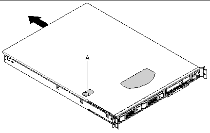
2. Set the cover aside and away from the immediate work area.
The following equipment is customer replaceable:
To access the system controls and peripherals when a front bezel is installed, grasp the bezel at the finger hole on the left side and gently pull it towards you, unhinging it at the right, until it unsnaps from the chassis. Replace the bezel using the reverse process (see FIGURE 5-2 and FIGURE 5-3).
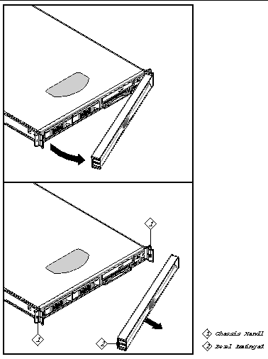
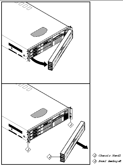
To replace the Floppy/CD-ROM module, follow these steps:
1. Before removing the cover to work inside the system, observe the safety guidelines previously stated.
2. Remove the bezel from the front of the chassis.
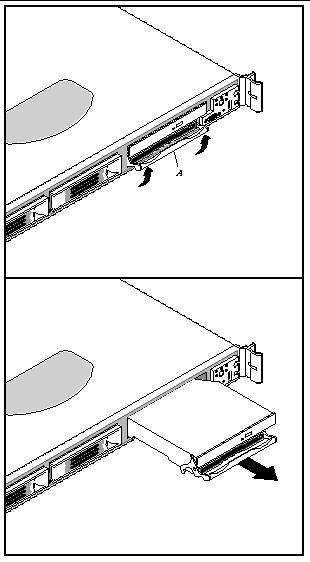
3. As shown in FIGURE 5-4, rotate the module's handle bar up (A) and pull on the handle bar to remove the module from the flex bay.
4. Slide a new module into the flex bay until you feel the connectors touch.
5. Push the module in (using the handle bar) about 3/16 of an inch (5mm) more to fully engage the connectors.
6. Rotate the handle bar down.
|
Note - The Comprehensive Test should be run after changing any FRU, CRU, or adding an optional component. See Run Platform Confidence Test (PCT). |

|
Caution - Before touching or replacing any component inside the server, disconnect all external cables and follow the instructions in Safety Guidelines (Before You Remove the Cover) and Removing and Replacing the Cover. Always place the server on a grounded ESD pad and wear a properly grounded antistatic wrist strap. |
The main board supports DDR-266 compliant registered[1] ECC DIMMs operating at 266 MHz.
Only tested and qualified DIMMs are supported on the main board. Note that all DIMMs are supported by design, but only fully tested DIMMs are supported.
The minimum supported DIMM size is 128 MB. Therefore, the minimum main memory configuration is 2 x 128 MB or 256 MB. The largest size DIMM supported is a 2 GB stacked registered DDR-266 ECC DIMM based on 512 megabit technology.
The memory system on the main board has the following features:
For part numbers of optional DIMMs, see TABLE 1-1 and TABLE 1-2.

|
Caution - Use of unauthorized DIMM modules may damage the server and may void the warranty. |
To replace DIMMs in a Sun Fire V60x server, follow these steps while referring to FIGURE 5-5:
1. Before removing the cover to work inside the system, observe the safety guidelines previously stated.
2. Release the DIMM from the connector slot by pressing down on the DIMM module ejector bars at both ends of the connector slot.
3. LIft the DIMM up and away from the connector slot.
4. With the ejector bars in the open position, align the replacement DIMM notch with the connector slot notch and apply even, downward pressure on the DIMM until it slides into the connector slot. The ejector bars will snap inward and lock the memory module in place.
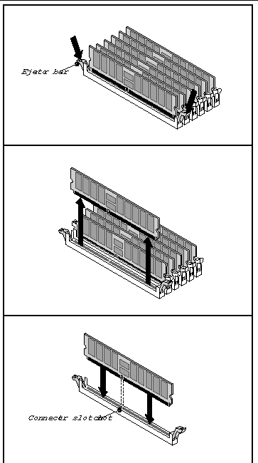
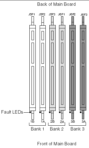
FIGURE 5-6 shows how the DIMM pairs are to be installed. They must be installed in pairs. There are three banks of DIMMs, labeled 1, 2, and 3. Bank 1 contains DIMM locations 1A and 1B, Bank 2 contains 2A and 2B, and Bank 3 contains 3A and 3B.
DIMM socket identifiers are marked on the silkscreen next to each DIMM socket on the baseboard. Note that the sockets associated with any given bank are located next to each other.
 [ D ]
[ D ]
|
Note - The Comprehensive Test should be run after changing any FRU, CRU, or adding an optional component. See Run Platform Confidence Test (PCT). |
1. Observe all safety precautions and remove the server top cover.
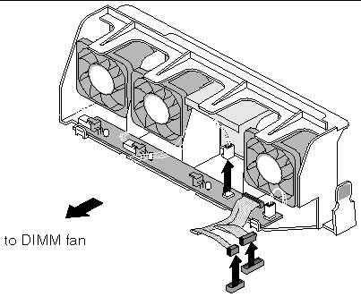
2. Remove the DIMM fan assembly by disconnecting the DIMM fan cable from the main fan module, then squeezing the vertical fan support bars to release the DIMM fan (see FIGURE 5-7).
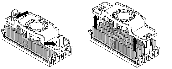
3. If you are replacing DIMMs whose ejector bars are engaged by the DIMM fan vertical support bars:
a. Do not remove the vertical fan support bars. Instead, spread apart the DIMM ejector bars using the vertical support bars. This will eject installed DIMMS from the sockets.
b. Place the new DIMMs in the sockets but do not press them all the way in, because the socket latches on each side are tied together by the vertical support bars.
c. Bring the two vertical support bars together enough to engage the keyed "half-moons" on all the DIMMs.
d. Gently press each DIMM, one at a time, to engage its socket, then firmly to fully seat.
4. If you are replacing DIMMs whose ejector bars are not engaged by the DIMM fan vertical support bars:
a. Make sure the ejector bars are in the open position.
b. Align the replacement DIMM notch with the connector slot notch and apply even, downward pressure on the DIMM until it slides into the connector slot. The ejector bars will snap inward and lock the memory module in place.
5. Replace the DIMM fan assembly as explained in Installing the DIMM Fan (Sun Fire V65x Server Only).
|
Note - The Comprehensive Test should be run after changing any FRU, CRU, or adding an optional component. See Run Platform Confidence Test (PCT). |
1. Observe all safety precautions and remove the server top cover.
2. Slide the DIMM fan assembly over the vertical support bars until the assembly snaps into place (see FIGURE 5-8 and follow steps a through d below).
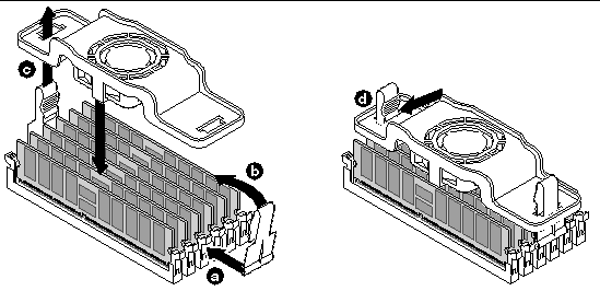
a. Orient the support bars so that the curved bottom aligns with the notches in the two middle DIMM ejector bars.
b. Gently push each support bar onto the two ejector bars until they are held firmly in place. Make sure the DIMMs stay securely seated in their sockets.
c. Slide the fan assembly down over the two support bars.
d. The flexible tabs at the top of the support bars lock the fan assembly in place.
3. Connect the DIMM fan cable to the 3-pin header on the server main fan pack (see FIGURE 5-9).

|
Caution - The procedure below is for the attention of qualified service engineers only. Before touching or replacing any component inside the Sun Fire V60x and Sun Fire V65x servers, disconnect all external cables and follow the instructions in Safety Guidelines (Before You Remove the Cover) and Removing and Replacing the Cover. Always place the server on a grounded ESD pad and wear a properly grounded antistatic wrist strap.
|

|
Caution - CPU replacement must be performed by trained service personnel only! An ESD wrist strap must be used for this procedure. |
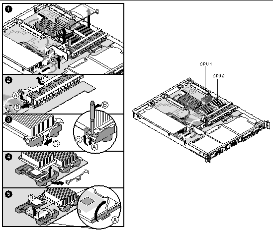
To remove the heatsink and processor, follow these steps while referring to FIGURE 5-10:
1. Remove the plastic air duct that covers the heatsinks and processors (see FIGURE 5-10).
2. Determine the location of the processor you are going to remove (see FIGURE 5-10).
CPU 2 is closest to the outside of the server and CPU 1 is toward the inside.
3. As shown in panel 1 of FIGURE 5-10, remove the processor air duct by lifting it up out of the chassis. Remove the air baffle by wiggling to loosen the tab from the backplane board. Lift the air baffle out of the chassis.
4. As shown in panel 2 of FIGURE 5-10, remove the fan module.
|
Note - In the Sun Fire V60x server, the fan module must be removed to access the retention clip nearest the front of the server. |
5. As shown in panel 3 of FIGURE 5-10, insert the heatsink retention clip removal tool into the hole in the end of one of the retention clips and then:
a. Use the tool to push the clip down.
b. Move the top of the tool toward the heatsink to release the clip from the tab on the heatsink retainer.
c. Release the pressure on the tool and allow the clip to come up so it clears the tab on the retainer.
d. Release the other end of the clip and slide the clip in a horizontal direction to free it from the middle tab.
6. Remove both retention clips and the heatsink as shown in panel 4.
a. Grasp the end of the socket lever and raise it to disengage the processor pins.
b. Lift the processor straight up out of the socket.

|
Caution - Do not place the thermal-pasted side of the processor or heatsink on any surface, as it may pick up contaminants, causing incorrect processor mating and possible overheating. |
Installing a replacement heatsink and processor is essentially the reverse of the procedure given in the previous section.
|
Note - When a processor kit includes new heatsink retention clips, use them in place of the old ones. |
|
Note - When installing a new processor or relocating a processor to a different main board, apply thermal paste as needed to the top of the processor. |

|
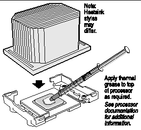
Caution - If you are installing a processor removed from a different server, you must prepare the processor and heatsink so that the heatsink properly conducts the heat away from the processor (see FIGURE 5-23). If the processor and heatsink are not properly prepared, damage to the processor or socket can result. You should not allow any surface that has thermal interface material to come in contact with any other surface, as surface contamination may occur. |
Follow these steps to replace the processor and heatsink:
1. Make sure the old processor has been removed and placed on an antistatic pad (or, if you are moving the processor from one main board to another, insert the processor directly into the new board as indicated in the next step).
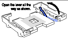
2. As shown in FIGURE 5-11, open the socket lever.
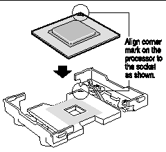
3. Align the corner mark on the processor with the mark on the socket.
4. Insert the processor into the socket as shown in FIGURE 5-12.
 [ D ]
[ D ]
5. Verify that the processor sits flush and level on the socket.
6. Close the socket lever until it locks and secures the processor in the socket.
Figure showing the direction to move the CPU socket locking lever to close it.

|
Caution - Move the socket lever slowly and make sure that it is engaged on the locking tab on the side of the socket. |
7. Orient the heatsink such that it properly and fully contacts the surface of the processor beneath it.
8. Gently lower the heatsink in place being careful not to damage the thermal interface material (TIM).
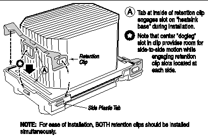
9. Install the heatsink retention clips using the retention clip tool.
 [ D ]
[ D ]
a. Secure each end of the retention clip to the tabs in the processor retainer by aligning the clip holes over the tabs and pushing down.
a. With the tool in the vertical position, firmly grasp it and insert the middle prong of the tool securely into the hole at the center of the retention clip.
b. Slowly and carefully push the tool downward, making sure the center prong of the tool stays in the retention clip hole.
c. As you continue to exert downward pressure, move the top of the handle slightly in a direction away from the heatsink so that the clip is pushed away from the retainer and the hole in the center of the clip is aligned over the retainer tab.
d. Gradually move the top of the tool handle back toward the heatsink in such as manner as to slide the center of the clip over the retainer tab, securing it in place.
10. Replace the air baffle, fan module, and processor air duct.
|
Note - The Comprehensive Test should be run after changing any FRU, CRU, or adding an optional component. See Run Platform Confidence Test (PCT). |
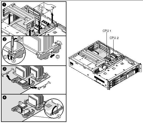
To remove the heatsink and processor, follow these steps while referring to FIGURE 5-15:
1. As shown in panel 1 of FIGURE 5-15, Remove the SCSI cable clipped to the left side of the processor air duct, then remove the processor air duct by sliding it slightly back and then lifting it from the front edge.
Remove the riser card assembly for better access to the CPU/heatsink, if desired.
2. Determine the location of the processor you are going to remove (see FIGURE 5-15).
CPU 2 is closest to the outside of the server and CPU 1 is toward the inside.
3. As shown in panel 2 of FIGURE 5-15, insert the heatsink retention clip removal tool into the hole in the end of one of the retention clips and then:
a. Use the tool to push the clip down.
b. Move the top of the tool toward the heatsink to release the clip from the tab on the heatsink retainer.
c. Release the pressure on the tool and allow the clip to come up so it clears the tab on the retainer.
d. Release the other end of the clip and slide the clip in a horizontal direction to free it from the middle tab.
4. Remove both retention clips and the heatsink as shown in panel 3.
a. Grasp the end of the socket lever and raise it to disengage the processor pins.
b. Lift the processor straight up out of the socket.

|
Caution - Do not place the thermal-pasted side of the processor or heatsink on any surface, as it may pick up contaminants, causing incorrect processor mating and possible overheating. |
Installing a replacement heatsink and processor is essentially the reverse of the procedure given in the previous section.
|
Note - When a processor kit includes new heatsink retention clips, use them in place of the old ones. |
|
Note - When installing a new processor or relocating a processor to a different main board, apply thermal paste as needed to the top of the processor. |

|
Caution - If you are installing a processor removed from a different server, you must prepare the processor and heatsink so that the heatsink properly conducts the heat away from the processor (see FIGURE 5-23). If the processor and heatsink are not properly prepared, damage to the processor or socket can result. You should not allow any surface that has thermal interface material to come in contact with any other surface, as surface contamination may occur. |
Follow these steps to replace the processor and heatsink:
1. Make sure the old processor has been removed and place it on an antistatic pad (or, if you are moving the processor from one main board to another, insert the processor directly into the new board as indicated in the next step).
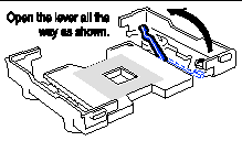
2. As shown in FIGURE 5-16, open the socket lever.
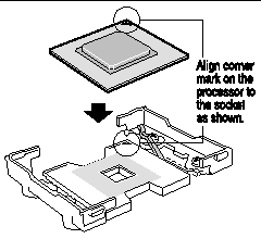
3. Align the corner mark on the processor with the mark on the socket.
4. Insert the processor into the socket as shown in FIGURE 5-17.
 [ D ]
[ D ]
5. Verify that the processor sits flush and level on the socket.
6. Close the socket lever until it locks and secures the processor in the socket.
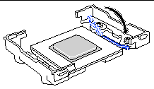

|
Caution - Move the socket lever slowly and make sure that it is engaged on the locking tab on the side of the socket. |
7. Orient the heatsink such that it properly and fully contacts the surface of the processor beneath it.
8. Gently lower the heatsink in place being careful not to damage the thermal interface material (TIM).
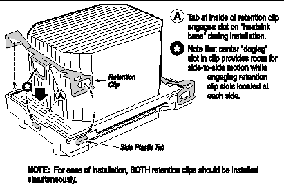
9. Install the heatsink retention clips using the retention clip tool.
 [ D ]
[ D ]
a. Secure each end of the retention clip to the tabs in the processor retainer by aligning the clip holes over the tabs and pushing down.
a. With the tool in the vertical position, firmly grasp it and insert the middle prong of the tool securely into the hole at the center of the retention clip.
b. Slowly and carefully push the tool downward, making sure the center prong of the tool stays in the retention clip hole.
c. As you continue to exert downward pressure, move the top of the handle slightly in a direction away from the heatsink so that the clip is pushed away from the retainer and the hole in the center of the clip is aligned over the retainer tab.
d. Gradually move the top of the tool handle back toward the heatsink in such as manner as to slide the center of the clip over the retainer tab, securing it in place.
10. Replace the air baffle, fan module, and processor air duct.
|
Note - The Comprehensive Test should be run after changing any FRU, CRU, or adding an optional component. See Run Platform Confidence Test (PCT). |
Installing a new processor and heatsink is an extra-cost option. This section describes how to install a new CPU and heatsink in a previously unpopulated CPU location.

|
Caution - The procedure below is for the attention of qualified service engineers only. Before touching or replacing any component inside the Sun Fire V60x and Sun Fire V65x servers, disconnect all external cables and follow the instructions in Safety Guidelines (Before You Remove the Cover) and Removing and Replacing the Cover. Always place the server on a grounded ESD pad and wear a properly grounded antistatic wrist strap. |

|
Caution - CPU installation must be performed by trained service personnel only! An ESD wrist strap must be used for this procedure. |
To install a new processor, follow these steps:
1. Remove any server items necessary to gain access to the CPU socket where you will install the new CPU and heatsink.
2. Following the instructions packaged with your boxed processor, prepare the new processor for installation.

|
Caution - You should not allow any surface that has thermal interface material to come in contact with any other surface, as surface contamination may occur. |
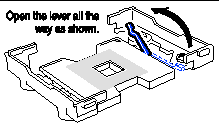
3. As shown in FIGURE 5-20, open the socket lever.
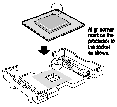
4. Align the corner mark on the processor with the mark on the socket.
5. Insert the processor into the socket as shown in FIGURE 5-21.
 [ D ]
[ D ]
6. Verify that the processor sits flush and level on the socket.
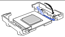
7. Close the socket lever until it locks and secures the processor in the socket.

|
Caution - Move the socket lever slowly and make sure that it is engaged on the locking tab on the side of the socket. |
8. If you have not already done so, apply thermal conducting material to the processor now (see FIGURE 5-23).
 [ D ]
[ D ]
9. Orient the heatsink such that it properly and fully contacts the surface of the processor beneath it.
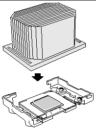
10. Gently lower the heatsink in place being careful not to damage the thermal interface material (TIM) as shown in FIGURE 5-24.
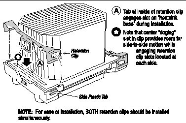
11. Install the heatsink retention clips using the retention clip tool.
 [ D ]
[ D ]
a. Secure each end of the retention clip to the tabs in the processor retainer by aligning the clip holes over the tabs and pushing down.
a. With the tool in the vertical position, firmly grasp it and insert the middle prong of the tool securely into the hole at the center of the retention clip.
b. Slowly and carefully push the tool downward, making sure the center prong of the tool stays in the retention clip hole.
c. As you continue to exert downward pressure, move the top of the handle slightly in a direction away from the heatsink so that the clip is pushed away from the retainer and the hole in the center of the clip is aligned over the retainer tab.
d. Gradually move the top of the tool handle back toward the heatsink in such as manner as to slide the center of the clip over the retainer tab, securing it in place.
|
Note - The Comprehensive Test should be run after changing any FRU, CRU, or adding an optional component. See Run Platform Confidence Test (PCT). |

|
Caution - Before touching or replacing any component inside the server, disconnect all external cables and follow the instructions in Safety Guidelines (Before You Remove the Cover) and Removing and Replacing the Cover. Always place the server on a grounded ESD pad and wear a properly grounded antistatic wrist strap. |
Before removing the cover to work inside the system, observe the safety guidelines previously mentioned.
Follow these steps to replace the Sun Fire V60x server power supply:
1. Unplug the power cord from the power source and the power supply module.
2. Lift the rear of the module up (FIGURE 5-26, panel 2) only enough to clear the raised guides on the chassis floor.

|
Caution - As shown in FIGURE 5-26, lift the rear of the power supply module up only enough to clear the raised guides. Lifting higher may damage the edge connector and power distribution board. |
3. Push the module to the rear of the chassis until it disengages from the power distribution board.
4. Lift the module out of the chassis.
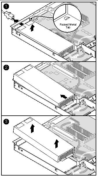
5. Place the edge connector end of the replacement module onto the chassis floor and slide it toward the front of the chassis until the edge connector is fully inserted in the power distribution board connector.
6. Make sure that the rear of the power supply is fully seated on the chassis floor and in front of the raised guides.
|
Note - The Comprehensive Test should be run after changing any FRU, CRU, or adding an optional component. See Run Platform Confidence Test (PCT). |
The default configuration for the Sun Fire V65x server is a single 500-watt power supply. Optionally, you can add a second power supply module to provide a redundant, 1+1 system.

|
Caution - If you do not have the second, redundant power supply module, you must take the server out of service before replacing the single module. |
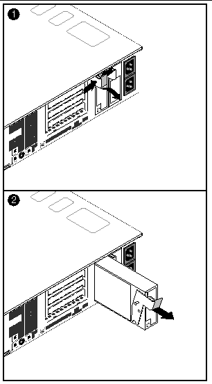
1. Squeeze the module handle to depress the latch (FIGURE 5-27, panel 1).
2. Rotate the handle down while pulling the module toward you
(FIGURE 5-27, panel 2).
3. As you pull the module out, support the module with your free hand.
4. Insert a new power supply module in the bay.
5. Grip the module handle, rotate it down, and push the module into the bay.
6. When the module is nearly all of the way in, the handle will rotate up. At this time, push firmly on the front of the handle to lock the latch.

|
Caution - Not all SCSI hard disk drives (HDD) are supported by the server. Unsupported drives will not mate mechanically with the connector on the inside of the drive bay. All drives must be LVDS SCA type (80-pin connector). The server does not support internal single-ended (SE) drives.
|
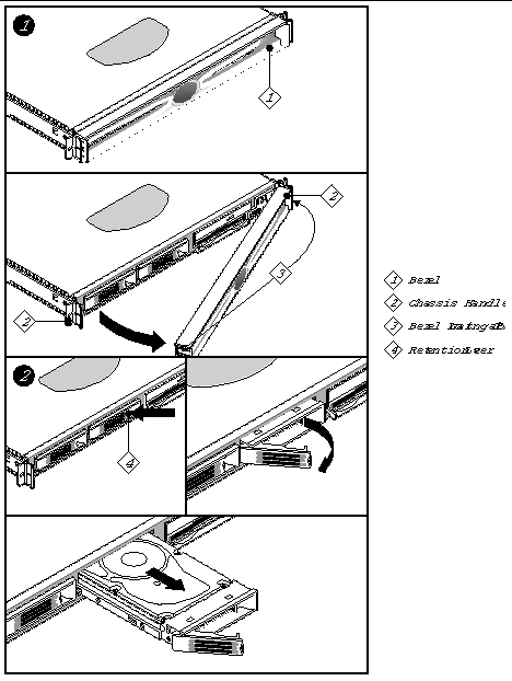
Follow these steps to replace a hard disk drive while referring to FIGURE 5-28:
1. Before removing the cover to work inside the system, observe the safety guidelines mentioned earlier.
2. Remove the bezel from the front of the chassis (see panel 1 of FIGURE 5-28).
3. As shown in panel 2 of FIGURE 5-28, push the green release tab in the retention lever and pull the HDD retention lever toward you until the tab end (left end) of the lever is free of the housing slot.
4. Pull the HDD assembly forward and out of the drive bay.
5. Remove the new HDD assembly (hard disk drive mounted on a carrier) from its wrapper and place it on an anti-static surface.
6. Install the new HDD assembly into the drive bay by inserting the tab end (left end) of the retention lever into the housing slot and gently closing the lever.
7. Reinstall a carrier in any bays where you are not reinstalling a HDD assembly.
|
Note - The Comprehensive Test should be run after changing any FRU, CRU, or adding an optional component. See Run Platform Confidence Test (PCT). |
This section explains how to remove and replace the air baffles for the servers.

|
Caution - Before touching or replacing any component inside the Sun Fire V60x and Sun Fire V65x servers, disconnect all external cables and follow the instructions in Safety Guidelines (Before You Remove the Cover) and Removing and Replacing the Cover. Always place the server on a grounded ESD pad and wear a properly grounded antistatic wrist strap. |
Follow the steps in this section to remove the air baffle.
1. Before removing the cover to work inside the system, observe the safety guidelines mentioned earlier.
3. Gently lift the air baffle until pin (C) is free of the board mounting hole.
4. Remove the baffle from the chassis.
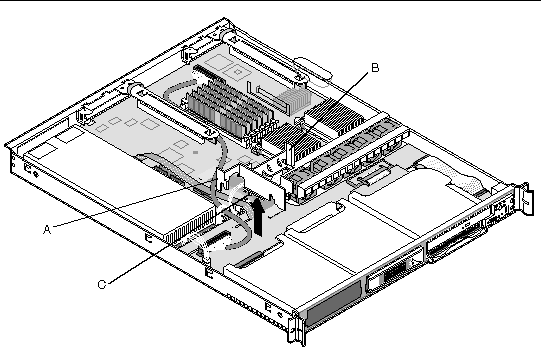
Follow these steps to install the air baffle:
1. Ensure the flex cable, auxiliary power cable, USB ribbon cable, and SCSI cables are routed under where you will be installing the air baffle.
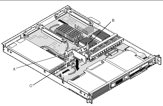
2. Aligning pin (C) with the board's mounting hole, position the air baffle over the white server board power connector.
3. Lower the baffle into position and press it down against the backplane board.
4. Ensure tab (A) aligns with the edge of the power supply and tab (B) aligns with the edge of the fan module.
To remove the air baffle, follow these steps:
1. Remove the blue thumbscrew holding the air baffle to the backplane board.
2. Lift the air baffle straight up, moving the SCSI cable out of the way.
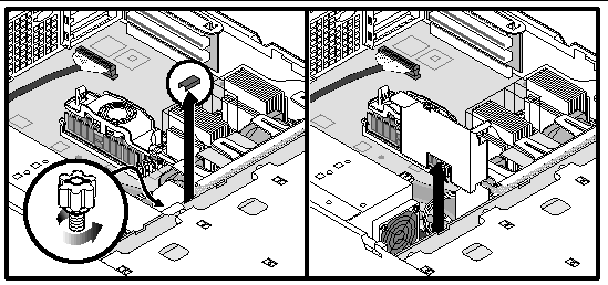
To replace the air baffle, follow these steps:
1. Slide the air baffle in place, ensuring that one tab is flat against the top of the power supply and the other tab is resting on top of the backplane board.
2. Route the SCSI cable through the slot on the top of the air baffle.
3. Secure the air baffle to the backplane using the blue thumbscrew.

|
Caution - Before touching or replacing any component inside the Sun Fire V60x and Sun Fire V65x servers, disconnect all external cables and follow the instructions in Safety Guidelines (Before You Remove the Cover) and Removing and Replacing the Cover. Always place the server on a grounded ESD pad and wear a properly grounded antistatic wrist strap. |
The fan assembly is a single component (see FIGURE 5-32). The individual fans that make up the assembly are not replaceable. Should a fan fail, the entire module will need to be replaced. A tab on the side of the fan module makes replacement of the module tool-less and very simple. The fan module is not hot swappable. The server must be turned off before the fan module can be replaced.
Before removing the cover to work inside the system, observe the safety guidelines previously given.
To replace the fan module, remove the cover and refer to FIGURE 5-32 when following these steps:
1. Remove the clear plastic processor air duct.
2. Remove the blue plastic air baffle.
3. Unplug the fan cable from the server board.
4. At the left end of the module, press the release tab.
5. While continuing to press the release tab, lift the left side of the fan module and slide it slightly left to free the "L" shaped foot at the right side of the fan module.
6. Remove the fan module from the chassis.
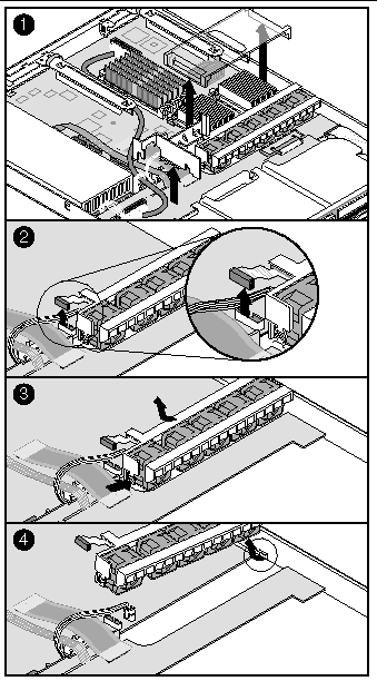
Replacing the fan module is essentially the reverse of the procedure described in Sun Fire V60x Server Fan Module Removal.
2. Remove the processor air duct.
3. Position the new fan module so that the fan cable is located closest to the center of the chassis.
4. Slide the "L" shaped foot on the chassis sidewall end of the fan module under the chassis tab.
5. Lower the module onto the chassis floor and slide it as far to the right as it will go.
6. Ensure that the fan module is situated between the raised guides, not on top of them.
7. Press down on the left end of the module and press in on the release tab until the tab snaps into the chassis slot.
8. Plug the fan module power cable into the system fan connector on the server board.
10. Replace the processor air duct.
11. Replace the chassis cover.
|
Note - The Comprehensive Test should be run after changing any FRU, CRU, or adding an optional component. See Run Platform Confidence Test (PCT). |
Unlike the fan module in the Sun Fire V60x server, the fans in the Sun Fire V65x server are individually replaceable. To replace an individual fan, first remove the fan module according to the instructions below while referring to FIGURE 5-33.
1. Remove the full-height PCI riser board.
2. Unthread the SCSI cable from the retaining hooks on the plastic processor air duct.
3. Push the air duct slightly toward the back of the chassis, then lift it by its front edge and remove it from the chassis.
4. Remove the flex circuit cable retention clip.
5. Disconnect the flex circuit cable from the backplane.
6. Unthread and remove the USB cable from the clips on top of the fan module.
7. Unplug the fan cables from the server board system fan connectors.
8. At the end of the fan module closest to the chassis centerline, push on the tab to release it from the chassis
9. While pushing on the tab, lift up on the module to clear the retention stub.
10. Slide the module towards the power supply until it comes free.
11. Lift the fan module out of the chassis.
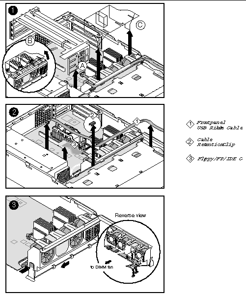
Replacing the fan module is essentially the reverse of the procedure described in Sun Fire V65x Server Fan Module Removal.
1. Note the raised tabs on the chassis floor and the corresponding notches in the bottom of the fan module.
2. Lower the fan module until it is just above the chassis floor.
3. Align the notches in the fan module with the raised tabs on the chassis and lower the fan module onto the floor.
4. While pressing down on the fan module, slide it to the right until the latch snaps into place.
5. Plug the fan cables into the server board system fan connectors.
6. Make sure the USB cable is routed along the top of the fan module.
7. Connect the flex circuit cable (floppy/FP/IDE) to the backplane.
8. Install the flex circuit cable retention clip.
9. Install the full-height PCI riser board.
10. Replace the plastic processor air duct.
11. Thread the SCSI cable through the retaining hooks on the plastic processor air duct.
12. Replace the chassis cover.
|
Note - The Comprehensive Test should be run after changing any FRU, CRU, or adding an optional component. See Run Platform Confidence Test (PCT). |
|
Note - Add-in cards must be replaced while the riser board is removed from the chassis.
|

|
Caution - Before touching or replacing any component inside the Sun Fire V60x and Sun Fire V65x servers, disconnect all external cables and follow the instructions in Safety Guidelines (Before You Remove the Cover) and Removing and Replacing the Cover. Always place the server on a grounded ESD pad and wear a properly grounded antistatic wrist strap. |
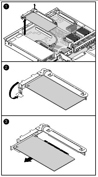
To replace a PCI card, follow these steps while referring to FIGURE 5-34:
1. Before removing the cover to work inside the system, observe the previously stated safety guidelines.
3. Insert your finger in the plastic loop on the PCI riser assembly.
4. Pull straight up and remove the riser assembly from the chassis.
5. Open the retainer clip on the riser card retention bracket.
6. Pull the PCI card out of the riser board slot.
7. Install the new PCI add-in card on the riser assembly.
8. Insert the riser assembly connector in the server board slot while aligning the tabs on the rear retention bracket with the holes in the chassis.
9. Firmly press the riser assembly straight down until it is seated in the server board slot.
10. Replace the chassis cover if you have no additional work to do inside the chassis.

|
Caution - Press the riser assembly straight down into the slot. Tipping it in the slot while installing it may damage the riser card or board slot. |
|
Note - The Comprehensive Test should be run after changing any FRU, CRU, or adding an optional component. See Run Platform Confidence Test (PCT). |

|
Caution - Before touching or replacing any component inside the Sun Fire V60x and Sun Fire V65x servers, disconnect all external cables and follow the instructions in Safety Guidelines (Before You Remove the Cover) and Removing and Replacing the Cover. Always place the server on a grounded ESD pad and wear a properly grounded antistatic wrist strap. |
The lithium battery on the server board powers the real time clock (RTC) for up to 10 years in the absence of power. A low battery condition is stored in the System Event Log (SEL).
When the battery starts to weaken, it loses voltage, and the server settings stored in CMOS RAM in the RTC (for example, the date and time) may be wrong. Contact your customer service representative or dealer for a list of approved replacement batteries.
1. Before proceeding, record your custom BIOS settings.
2. Observe the safety and ESD precautions at the beginning of this chapter.
3. Open the chassis and locate the battery (on the main board, near the left front corner).
4. Push the upper end of the metal retainer away from the battery so that the battery pops up (see FIGURE 5-35).
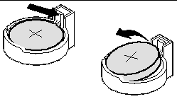
5. Remove the battery from its socket.
6. Dispose of the battery according to local ordinances.
7. Remove the new lithium battery from its package.
8. Being careful to observe the correct polarity, lay the battery in the socket.
9. Push the battery down so that the metal retainer locks the battery in the socket.
11. Run the BIOS setup (press F2 when prompted at bootup) to restore the configuration settings to the RTC.
12. Restore your custom BIOS settings.
|
Note - The Comprehensive Test should be run after changing any FRU, CRU, or adding an optional component. See Run Platform Confidence Test (PCT). |
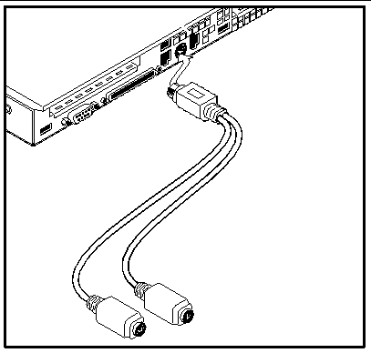
To install the PS/2 keyboard/mouse "Y" adapter, install the adapter into the round keyboard/mouse connector as shown in FIGURE 5-36.
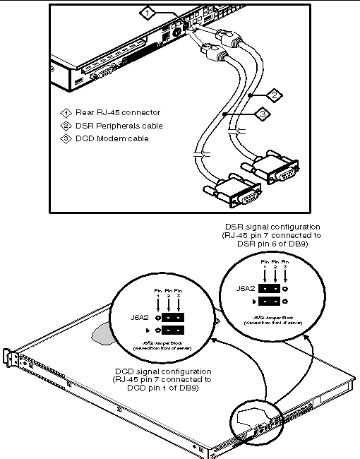
Two different serial port adapters may be installed into the rear panel RJ-45 Serial COM2 Emergency Management Port (EMP) connector:
Follow these steps to install the DSR Peripherals cable:
1. Plug the DSR Peripherals cable into the rear panel RJ-45 Serial COM2 connector as shown in FIGURE 5-37.
2. Configure the J5A2 jumper as shown in FIGURE 5-37.
Follow these steps to install the DCD Modem cable:
1. Plug the DCD Modem cable into the rear panel RJ-45 Serial COM2 connector as shown in FIGURE 5-37.
2. Configure the J5A2 jumper as shown in FIGURE 5-37.
 [ D ]
[ D ]
This section explains how to replace the FRUs in the Sun Fire V60x and Sun Fire V65x servers.
|
Note - The Main Board contains no DIMMs or CPUs, and is packaged in an ESD bag with two foam pieces and an ESD wrist strap. Be sure to observe all ESD safety guidelines when handling the board. |

|
Caution - The procedure below is for the attention of qualified service engineers only. Before touching or replacing any component inside the Sun Fire V60x and Sun Fire V65x servers, disconnect all cables and follow the instructions in Safety Guidelines (Before You Remove the Cover) and Removing and Replacing the Cover. Always place the server on a grounded ESD pad and wear a properly grounded antistatic wrist strap. |
|
Note - Several assemblies must be removed so that the main board can be replaced. Refer to other sections of this chapter for detailed instructions on how to remove and replace these assemblies. |
To replace the Sun Fire V60x server Main Board, follow these steps:
1. Open the box containing the replacement board and remove one of the two antistatic pads. You will need this pad in step 17 as an ESD-safe place to place the old server board.
2. Before removing the cover to work inside the system, observe the previously mentioned safety guidelines.
3. Remove the cover and bezel from the chassis.
4. Remove all drives from the drive bays and flex bay.
5. Remove the PCI riser board assemblies.
8. Unscrew and remove the blue plastic retention clip that holds down the flex cable onto the server board.
9. At the backplane board, disconnect the ribbon cable from the front panel board.
10. Remove the processor air duct.
11. Disconnect the fan cable from the server board and remove the fan module.
12. Disconnect both ends of all remaining cables that connect the main board to other chassis components.
|
Note - Some cables may be soldered at one end. Remove only the connectorized end. |
13. Remove the backplane board.
14. Disconnect the USB ribbon cable from the server board and lay the free end back over the drive bays.
15. Remove the heat sink, processor air dam, and any processors and memory DIMMs that you wish to use with the new board.
16. Remove the eight screws that secure the processor retention mechanisms and the three mounting screws that secure the server board to the chassis (see FIGURE 5-38).
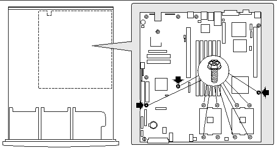
17. Slide the board toward the front of the chassis until the I/O connectors are clear of the chassis I/O openings, lift the server board from the chassis, and place it on an antistatic pad.
18. Remove the power distribution board from the white 24-pin power connector. Place the server board in an antistatic bag.
19. Remove the replacement server board from its packaging and antistatic bag.
20. Connect the power distribution board to the 24-pin power connector on the new server board.
21. Ensure that the Mylar insulator sheet is seated securely over the standoffs, is laying flat on the chassis floor, and that the edge of the sheet is seated below the studs in the rear chassis wall.
22. Insert the back edge of the board under the three retention pins located at the rear of the chassis.
23. While placing the board on the chassis standoffs, carefully align the board I/O connectors with the rear chassis I/O openings.
24. Adjust the board's position so that the three mounting holes rest securely on the shouldered standoffs.
25. Reattach the board to the chassis using the three mounting screws.
|
Note - The server board uses three holes to mount the board to the chassis standoffs. |
26. Install the processor retention mechanisms using the eight screws you removed earlier, along with the processor(s), heatsink(s), and DIMMs that you wish to use with the new board.
27. If you only have one processor, install the processor air dam in the outer processor location.
28. Lay the USB ribbon cable in the proper position on the chassis floor, under where the backplane board will be installed, and connect it to the USB connector on the server board.
29. Install the backplane board.
31. Install the cables between the new server board and the other system components.
32. Install the fan module and connect the fan cable to the server board.
34. With a screw, install the blue plastic retention clip that holds down the flex cable onto the server board.
35. Install the processor air duct.
36. Install both PCI riser board assemblies.
37. Replace all drives in the drive bays and flex bay.
38. Replace the chassis cover if you have no additional work to do inside the chassis.
|
Note - The Comprehensive Test should be run after changing any FRU, CRU, or adding an optional component. See Run Platform Confidence Test (PCT). |
|
Note - Several assemblies must be removed so that the main board can be replaced. Refer to other sections of this chapter for detailed instructions on how to remove and replace these assemblies. |
To replace the Sun Fire V65x server Main Board, follow these steps:
1. Open the box containing the replacement board and remove one of the two antistatic pads. You will need this pad in step 17 as an ESD-safe place to place the old server board.
2. Before removing the cover to work inside the system, observe the previously mentioned safety guidelines.
3. Remove the cover and bezel from the chassis.
4. Remove the PCI riser board assemblies.
6. Unscrew and remove the blue plastic retention clip that holds down the flex cable onto the server board.
7. Disconnect the USB ribbon cable from the server board, unthread it from the top of the fan module, and lay the free end back over the drive bays.
8. Remove the processor air duct.
9. Disconnect the fan cables from the server board and the DIMM fan power cable from the fan module header and remove the fan module.
10. Remove the DIMM fan and vertical support bars.
11. Disconnect both ends of all remaining cables that connect the main board to other chassis components (including the power supply).
|
Note - Some cables may be soldered at one end. Remove only the connectorized end. |
12. Remove the heat sink, processor air dam, and any processors and memory DIMMs that you wish to use with the new board.
13. Remove the eight screws that secure the processor retention mechanisms and the three mounting screws that secure the server board to the chassis (see FIGURE 5-39).
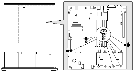
14. Slide the board toward the front of the chassis until the I/O connectors are clear of the chassis I/O openings, lift the server board from the chassis, and place it on an antistatic pad.
15. Remove the replacement server board from its packaging and antistatic bag.
16. Ensure that the Mylar insulator sheet is seated securely over the standoffs, is laying flat on the chassis floor, and that the edge of the sheet is seated below the studs in the rear chassis wall.
17. Insert the back edge of the board under the three retention pins located at the rear of the chassis.
18. While placing the board on the chassis standoffs, carefully align the board I/O connectors with the rear chassis I/O openings.
19. Adjust the board's position so that the three mounting holes rest securely on the shouldered standoffs.
20. Reattach the board to the chassis using the three mounting screws.
|
Note - The server board uses three holes to mount the board to the chassis standoffs. |
21. Install the processor retention mechanisms using the eight screws you removed earlier, along with the processor(s), heatsink, and DIMMs that you wish to use with the new board.
22. If you only have one processor, install the processor air dam in the outer processor location.
23. Install the fan module and connect the fan cables to the server board.
24. If you are using the DMII fan assembly form the old main board, install the DIMM fan assembly and connect the DIMM power cable to the DIMM fan power connector on the fan module.
25. Rethread the USB ribbon cable through the clips on the top of the fan module and connect the USB cable to the USB connector on the server board.
26. Install the cables between the new server board and the other system components (including the power supply).
28. With a screw, install the blue plastic retention clip that holds down the flex cable onto the server board.
29. Install the processor air duct.
30. Install both PCI riser board assemblies.
31. Replace the chassis cover if you have no additional work to do inside the chassis.
|
Note - The Comprehensive Test should be run after changing any FRU, CRU, or adding an optional component. See Run Platform Confidence Test (PCT). |

|
Caution - The procedure below is for the attention of qualified service engineers only. Before touching or replacing any component inside the Sun Fire V60x and Sun Fire V65x servers, disconnect all external cables and follow the instructions in Safety Guidelines (Before You Remove the Cover) and Removing and Replacing the Cover. Always place the server on a grounded ESD pad and wear a properly grounded antistatic wrist strap. |
You can use the cable kit to replace one or more internal server cables. The procedures given below assume that you are removing and replacing all of the cables.
Before removing the cover to work inside the system, observe the safety guidelines previously given.
To remove cables, remove the cover and refer to FIGURE 5-40, FIGURE 5-41, and FIGURE 5-42 while following these steps:
3. Unscrew and remove the blue plastic flex cable retention clip from the server board.
4. Remove all hard disk drives (including blanks) and the floppy/CD-ROM combo drive.
5. Unplug the backplane power cable, server board auxiliary signal cable, and server board auxiliary power cable, shown in FIGURE 5-40, panel 2.
6. Remove the round SCSI cable.
7. Remove the flex circuit cable (floppy/FP/IDE) that runs from the connector on the server board to the connector on the backplane.
8. Remove the front panel cable that runs from the front panel board to the backplane.
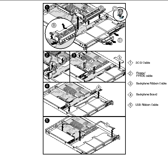
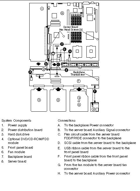 [ D ]
[ D ]
9. Remove the SCSI backplane board (this must be done to access the USB ribbon cable), while referring to FIGURE 5-42.
a. Unplug all cables from the backplane.
b. Remove the blue thumbscrew (A) from the right side of the backplane.
c. Grasp the backplane and slide it slightly to the right to free it from the round standoff posts (B, C) that protrude up through the mounting holes.
d. Gently lift out the backplane board and set it aside.
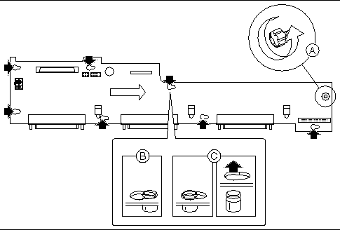
10. The full USB cable (FIGURE 5-41, E) is now uncovered and may be unplugged and removed from the front panel board and from the server board.
To replace cables, remove the cover and refer to FIGURE 5-40, FIGURE 5-41, and FIGURE 5-42 while following these steps:
1. If you previously removed the SCSI backplane board to remove the USB cable:
a. Replace the USB cable by connecting it from the front panel board to the USB connector (FIGURE 5-41, E) on the server board.
b. Replace the SCSI backplane board:
i. Place the board over all six of the round standoff posts.
ii. Slide the board to the left until it is fully secured by the standoffs.
iii. Install the thumbscrew at the right side of the board.
2. Route the front panel cable (FIGURE 5-41, F) from the front panel board to the backplane and attach it to the matching connector.
3. Attach one end (P1) of the flex circuit cable (FIGURE 5-41, C) to the floppy/front panel/IDE connector on the server board.
4. Secure the P1 end of the flex cable with the blue plastic screw-in retention clip.
5. Route the flex cable to the backplane board and attach the opposite cable end to the matching connector on the backplane.
6. Connect the auxiliary signal cable (FIGURE 5-41, B) from the power distribution board to the 5-pin auxiliary signal connector on the server board.
7. Route the power cable (A) from the power distribution board to the backplane board and insert it in the white 6-pin connector.
8. Route the auxiliary power cable (H) from the power distribution board to the server board and insert it in the white 8-pin connector.
9. On the round SCSI cable (D), locate the end that is labeled server board. Connect that end to the SCSI connector on the server board. Route the cable between the PCI connector and memory slots on the server board and then to the backplane board. Attach the cable connector to the connector on the backplane board.
12. Replace the top cover of the server
|
Note - The Comprehensive Test should be run after changing any FRU, CRU, or adding an optional component. See Run Platform Confidence Test (PCT). |
Before removing the cover to work inside the system, observe the safety guidelines previously given.
To remove cables, remove the cover and refer to FIGURE 5-43 and FIGURE 5-44 when following these steps:
1. Insert your fingers under the blue plastic loops on the full-height PCI riser card and pull the riser card straight up out of the chassis.
2. Unscrew the air baffle screw and remove the floppy/FP/IDE flex cable retention clip.
4. Unscrew and remove the plastic retention clip that holds the flex cable connector to the SCSI backplane.
5. Remove the floppy/FP/IDE flex circuit cable that runs from the connector on the server board to the connector on the backplane.
6. Remove the front panel cable that runs from the front panel board to the backplane.
7. Remove the USB cable that runs from the connector on the front panel board, through the clips on top of the fan module, to the connector on the server main board.
8. Remove the SCSI cable that runs from the SCSI backplane to the server board.
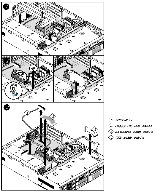
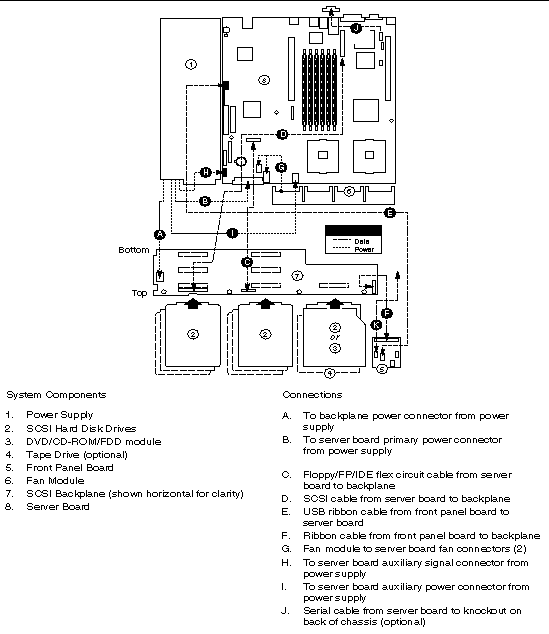 [ D ]
[ D ]
Before removing the cover to work inside the system, observe the safety guidelines previously given.
To replace cables, remove the cover and refer to FIGURE 5-44 through FIGURE 5-46 when following these steps:
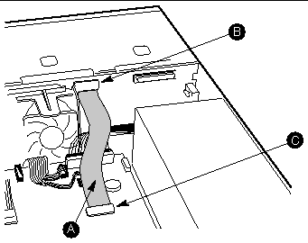
1. Install the flex cable (A) between the backplane connector (B) and the server board connector (C) (see FIGURE 5-45).
Make sure the end marked "P1-Serverboard" plugs into the server board.
2. Install the flex cable retention clip on the SCSI backplane as shown in FIGURE 5-46.
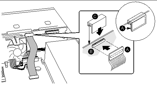
3. Install the screw-in blue plastic retention clip to hold the flex cable connector in place on the server board.
4. Connect both ends of the SCSI cable (FIGURE 5-44, D), making sure it routes through the air baffle notch next to the power supply.
5. Install the front panel cable (FIGURE 5-44, F) between the front panel and the SCSI backplane.
6. Install the USB cable (FIGURE 5-44, E).
a. Connect the USB Cable to the front panel board.
b. Connect the USB cable to the main board.
c. Route the USB cable under the black plastic flap and hooks at the top of the fan module to keep it securely in place.
|
Note - The Comprehensive Test should be run after changing any FRU, CRU, or adding an optional component. See Run Platform Confidence Test (PCT). |

|
Caution - The procedure below is for the attention of qualified service engineers only. Before touching or replacing any component inside the server, disconnect all external cables and follow the instructions in Safety Guidelines (Before You Remove the Cover) and Removing and Replacing the Cover. Always place the server on a grounded ESD pad and wear a properly grounded antistatic wrist strap. |
A System FRU is the Main Board with SCSI backplane, power supply, power supply distribution board (Sun Fire V60x server), front-panel board, fan module and all cables, in a Sun Fire V60x server or Sun Fire V65x server chassis. The System FRU contains no CPU(s), HDDs, Floppy/CD-ROM/DVD combo or DIMMs. The field engineer transfers the customer's CPU(s), HDDs, Floppy/CD-ROM/DVD combo and DIMMs to the new assembly. There are special CPU/heatsink procedures that must be followed when disassembling heatsinks from processors (see Replacing a Server CPU and Heatsink).
|
Note - The Comprehensive Test should be run after changing any FRU, CRU, or adding an optional component. See Run Platform Confidence Test (PCT). |
Before removing the cover to work inside the system, observe the safety guidelines previously given.
To install the system FRU, follow these steps while referring to FIGURE 5-47:
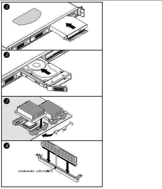
1. Install the floppy/CD-ROM combo drive (see Floppy/DVD/CD-ROM Combo Module for details).
2. Install the hard disk drives (see Hard Disk Drives for more details).
3. Install the heatsinks and CPUs (see Replacing a Server CPU and Heatsink for more details).
4. Install the DIMMs (see Memory for more details).
Copyright © 2003, Sun Microsystems, Inc. All rights reserved.