Key Switch Lock Cable Assembly
Removing the Key Switch Lock Cable Assembly
-
Remove the panels covering the key switch lock cable assembly.
Complete the steps in "Removing the Front and Side Panels".
-
Disconnect the key switch lock cable from the LED board.
-
Pull forward on the two locking tabs securing the cable to the LED board.
The key switch lock cable is in front of the key switch PWB centerplane cable. See Figure E-7.
-
Disconnect the cable.
-
-
Remove the two screws that attach the key switch lock assembly to the chassis.
-
Twist the key switch lock assembly to the left and pull it forward and out away from the chassis.
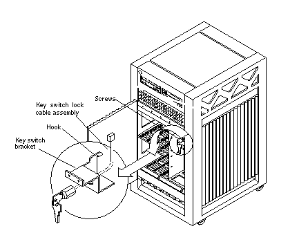
The key switch lock assembly has a hook that sits on the bracket in the chassis. You need to turn the assembly so that the hook clears the bracket before the key switch lock assembly can be removed. See Figure E-10.
Figure E-10 Removing the Key Switch Lock Cable Assembly

-
Separate the key switch lock cable from the key switch bracket.
-
Remove the U-shaped key switch keeper by pulling it straight out away from the key switch lock assembly.
The key switch keeper is located on the inside of the key switch bracket and secures the cable to the bracket.
-
Remove the key switch lock cable by pulling it through the keyhole. See Figure E-10.
-
Replacing the Key Switch Lock Cable Assembly
-
Secure the key switch lock cable to the key switch bracket.
-
Insert the key switch lock cable into the keyhole of the key switch bracket.
Position the key switch lock cable so that the arrow on the front of the cable assembly is turned upward. See Figure E-10.
-
Secure the key switch lock cable to the bracket using the key switch keeper.
Slip the key switch keeper into the groove on the cable to secure the cable to the bracket.
-
-
Twist the key switch lock assembly to the left and thread it through the round hole in the right front side of the chassis.
-
Twist the key switch lock assembly to the right so that the hook rests on the bracket in the chassis. See Figure E-10.
-
Replace the two screws that attach the key switch lock assembly to the chassis.
-
Connect the key switch lock cable to the LED board.
Note -The key switch lock cable is keyed so that the cable fits into the connector in only one direction and cannot be reversed.
-
Connect the cable.
The key switch lock cable is in front of the key switch PWB centerplane cable. See Figure E-9.
-
Push back on the two locking tabs and secure the cable to the LED board.
The two locking tabs fit over the connector, securing the key switch lock cable assembly to the LED board.
-
-
Replace the panels covering the key switch lock assembly.
Complete the steps in "Replacing the Front and Side Panels".
- © 2010, Oracle Corporation and/or its affiliates
