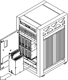
Replacing the Thermal Protection Module or Auxiliary Peripheral Power Supply (PPS1)
All Enterprise 3500 systems must have either a thermal protection module or an auxiliary peripheral power supply (PPS1) installed in the PPS1 slot in the front of the system.
Removing a Thermal Protection Module
-
Use the key provided to unlock and open the system front door.
-
Grasp the handle on the thermal protection module and firmly pull the module toward you, out of the PPS1 slot in the system chassis.
-
Before powering on the system, install an auxiliary peripheral power supply or return the thermal protection module to the PPS1 slot.
Replacing an Auxiliary Peripheral Power Supply
Remove and replace the auxiliary peripheral power supply (PPS 1) in a running system but not in the low power mode. In low power mode, the front panel and board LEDs are all off, while the yellow LEDs are lit on the power supplies. Replacing the PPS (PPS 1) during low power mode causes the system to power on immediately.
-
Use the key provided to unlock and open the system front door.
-
Release the power supply from the system chassis by loosening the captive screws.
-
Pull the ends of the extraction levers outward to release the power supply from the centerplane.
-
Pull the power supply straight out.
You will see a message similar to the following example on your system console:
NOTICE: Peripheral Power Supply 1 Removed
Figure 7-5 Replacing the Auxiliary Peripheral Power Supply (PPS1)

-
Carefully insert the replacement power supply in the PPS1 slot.
Ensure that both extraction levers are in the outward position. The power supply will not seat fully unless the levers are in this starting position.
-
Slide the power supply toward the centerplane.
 Caution -
 DO NOT FORCE the power supply into a slot; this can cause damage to the power supply and system.
The power supply should insert and seat smoothly. If it binds, remove it, and inspect the slot for any obvious obstructions.
-
Use the extraction levers to seat the power supply.
Simultaneously swing both levers inward to the locked position. Do not press on the front panel of the power supply to seat it--doing so will damage the connector pins.
-
Lock the power supply to the system chassis by tightening the captive screws.
-
Check to be sure the green LED on the power supply is lit.
If the green LED is not lit, the power supply may not be seated properly. Check to see if it is seated properly by repeating Step 5 to Step 9. If the green LED is still not lit, see Table 10-6 for more information.
If the green LED is lit, you will see a message similar to the following example on your system console:
NOTICE: Peripheral Power Supply 1 Installed

NOTICE: Peripheral Power Supply 1 OK
- © 2010, Oracle Corporation and/or its affiliates
