| C H A P T E R 1 |
|
Sun Fire X2200 M2 Server Overview |
This chapter provides an overview of the Sun Fire X2200 M2 server, as well as power-on and power-off procedures and information about installing components.
The following sections are included in this chapter:
TABLE 1-1 lists the system’s key components.
This section describes the operating system and additional software that is supported for the Sun Fire X2200 M2 server.
If you ordered a hard drive with your Sun Fire X2200 M2 server, the hard drive might have the Solaris 10 6/06 Operating System with Java
 Enterprise System (Java ES) installed, as well as Sun
 Studio 1l developer software.
For information on configuring the preinstalled Solaris 10 OS for the Sun Fire X2200 M2 server, refer to the Sun Fire X2200 M2 Server Installation Guide.
For further information on the Solaris 10 OS, see the Solaris 10 OS documentation at:
The following operating systems are supported for the Sun Fire X2200 M2 server:
For an updated list of supported version for each OS, go to:
For information about installing a supported operating systems, see:
For the OS issues and late-breaking information, see:
For supported versions of Red Hat Enterprise Linux or SUSE Linux Enterprise Server, go to:
The Sun Fire X2200 M2 Server Tools and Drivers CD, included with the server, contains drivers for operating system installation, LSI and NVIDIA RAID drivers, BIOS/BMC flash utilities, diagnostics software, Windows Remote Installation Service (RIS) files, and Broadcom NetXtreme software.
For more information on using the Tools and Drivers CD software, see Appendix B.
An IPMI 2.0-compatible service processor with Embedded Lights Out Manager is integrated onto the Sun Fire X2200 M2 motherboard. See the Embedded Lights Out Manager Administration Guide for more information on system management.
The following sections describe the hardware and features of your Sun Fire X2200 M2 server.
FIGURE 1-1 shows the front panel of the Sun Fire X2200 M2 server.
FIGURE 1-1 shows the back panel of the Sun Fire X2200 M2 server.
|
Broadcom Ethernet connectors (LAN-0 top,
|
|||
FIGURE 1-3 shows the locations of the components inside the Sun Fire X2200 M2 server.
FIGURE 1-3 Sun Fire X2200 M2 Server System Components
This section includes instructions for powering the server on and off and placing the server in standby power mode.
|
1. Connect grounded AC power cords to the AC power connector on the back panel of the server and to a grounded AC power outlet.
2. Continue with initial software setup tasks, as described in Sun Fire X2200 M2 Server Installation Guide.
|
 To power on main power for all server components:
a. Verify that the power cord has been connected and that standby power is on.
In standby power mode, the Power/OK LED on the front panel flashes. See FIGURE 1-1.
b. Use a ballpoint pen or stylus to press and release the recessed Power button on the server front panel.
When main power is applied to the full server, the Power/OK LED next to the Power button lights and remains lit.
|
 To power off the server from main power mode, use one of the following methods:

|
Caution - To completely power off the server, you must disconnect the AC power cords from the back panel of the server. |
Use this procedure to clear the server's CMOS settings in the case of a system hang. For example, if the server hangs because of incorrect settings and will not boot, use this procedure to invalidate the settings and reboot with the default settings.
|
See FIGURE 1-2 for the location of the power cord connection.
2. Remove the server’s top cover.
See Section 4.3, Powering Off the Server and Removing the Cover.
See Section 4.4.6, Replacing an Air Duct
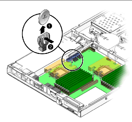
4. Remove the system battery by pulling it up and out of the holder (see FIGURE 1-4).
FIGURE 1-4 Removal of Battery and Clearing of CMOS

The battery is secured in the battery holder by a metal clip that contacts the positive (‘+’) side of the battery. To clear CMOS, you must make the metal clip and the contact point in the battery holder touch (short) for a period of 60 seconds.
5. Press the metal clip on the battery holder inward until it touches (shorts) the metal contact point in the base of the battery holder (seeFIGURE 1-4).
You can use your thumb and finger to press (squeeze) the clip against the contact point.
6. Continue shorting the clip and the contact point for a period of 60 seconds.
The two points must touch (short) for 60 seconds.
7. After 60 seconds, install the battery, making certain that the positive (‘+’) side of the battery faces outward (see FIGURE 1-4) and contacts the metal clip.
8. Install the air duct, and secure it with the air duct retaining screw.
9. Reinsert the AC power cord.
You can order additional components and replacement parts for the Sun Fire X2200 M2 server.
Contact your local Sun sales representative for more information. For the most up-to-date component information, see the components list on one of the following web sites:
http://sunsolve.sun.com/handbook_pub/Systems/
Copyright © 2008, Sun Microsystems, Inc. All Rights Reserved.