| C H A P T E R 4 |
|
Maintaining the Sun Fire X2200 M2 Server |
This chapter describes how to add, replace, and configure components in the Sun Fire X2200 M2 Server server after it has been set up.
This chapter contains the following sections:
To determine and isolate a faulty component, refer to Performing Diagnostics.
You need the following tools and supplies for performing Sun Fire X2200 M2 server maintenance procedures.
Before removing the system’s top cover, read the following sections. These sections contain important electrostatic discharge (ESD) precautions, along with preinstallation and postinstallation instructions.
ESD can damage your processor, disk drives, expansion boards, and other components. Always observe the following precautions before you install a system component.
Always perform the following steps before you install any component:
1. Turn off the system and all of the peripherals connected to it.

|
Caution - Failure to properly turn off the system before you start installing components can cause serious component damage. |

|
Caution - Follow the ESD precautions described in Section 4.2.1, ESD Precautionswhen handling a system component. |
See Section 4.3, Powering Off the Server and Removing the Cover for the appropriate procedure for opening the server.
Perform the following steps after installing a server component.
1. Ensure that all of the components are installed as described in the step-by-step instructions.
See Section 4.4, Component Replacement Procedures.
2. Reinstall any PCI Express (PCIe) cards or peripherals that you had previously removed.
See Section 4.4, Component Replacement Procedures.
3. Reinstall the system’s cover.
See Section 4.3, Powering Off the Server and Removing the Cover.
4. Connect all external cables to the system.
For your safety, perform this procedure when you are powering off the system and removing the cover for a maintenance procedure in this chapter.
|
1. If the operating system (OS) is running, perform a shutdown of the OS, and then press and release the platform power button on the front panel.
2. Turn off all peripheral devices connected to the system.
3. Disconnect the AC power on the back panel of the server (see FIGURE 1-2).
4. Label and disconnect all peripheral cables and all telecommunication lines connected to I/O connectors or ports on the back panel of the system.

|
Caution - The system’s printed circuit boards and hard disk drives contain components that are extremely sensitive to static electricity. |
5. Before handling components, attach a wrist strap to a chassis ground (any unpainted metal surface).
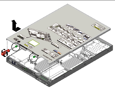
6. Loosen the two captive screws securing the cover to the chassis (see FIGURE 4-1).
7. Pull the cover slightly toward the back of the server and then straight up to remove it.
8. Lift the cover and remove it.
FIGURE 4-1 Removing the Server Cover
For the location of server components referenced in this section, see Section 1.3.2, Internal Components.
The following components are customer-replaceable units (CRUs):
The following component should be replaced only by trained field service technicians:
| Note - Many of the illustrations in this section show multiple PCIe slots on the motherboard. The Sun Fire X2200 M2 server motherboard will only have a single PCI Express slot. |
The following procedures describe how to remove and install an I/O board.
|
1. Power off the server, including any attached peripherals, and disconnect the server from the electrical outlet. Refer to Section 4.3, Powering Off the Server and Removing the Cover.
2. Remove all cables connected to the I/O board.
3. Remove the screws securing the I/O board to the DVD cage.
FIGURE 4-2 Removing the I/O Board
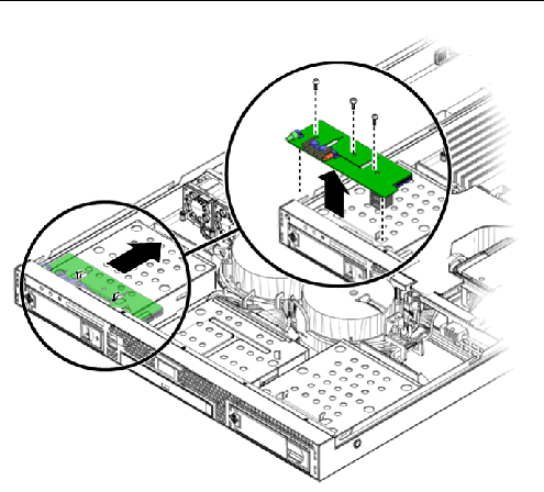
4. Pull the I/O board back slightly, then upwards to disengage the board from the guides on top of the HDD cage.
|
1. Position the I/O board on top of the HDD cage so the openings on the board line up with the guides on top of the HDD cage.
FIGURE 4-3 Installing the I/O Board
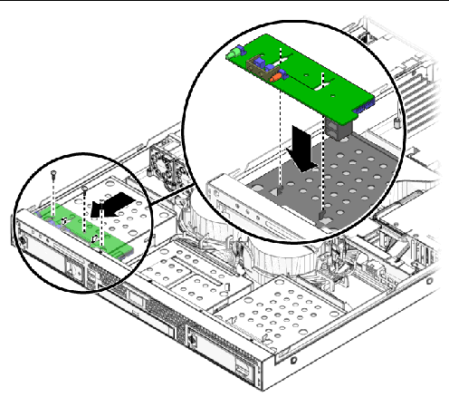
2. Gently push the I/O board down to engage the guides and push the board forward to secure it.
3. Fasten the screws to secure the I/O board to the mounting bracket.
5. Before reinstalling the cover on the server, check the routing of all cables for obstructions.
This section describes how to remove and install the PCIe card and riser assembly. The X2200 M2 server can accommodate either an x8 or an x16 riser assembly. The x8 is a low-profile, half-length dual connector card that supports up to two 25W cards. The x16 riser assembly is a low-profile half-length single connector card for the Nvidia Quadro Plex graphic cards. See
|
1. Power off the system and remove the cover as described in Section 4.3, Powering Off the Server and Removing the Cover.
2. Placing your fingers on the two green areas on the riser assembly, pull the assembly upward and out of the chassis.
FIGURE 4-4 Removing the PCIe Card Riser Assembly
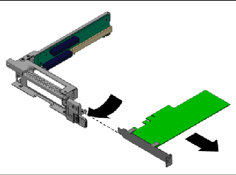
3. Unlatch the PCIe card and remove the card from the PCIe card riser assembly connector. See FIGURE 4-5.
FIGURE 4-5 Removing a PCIe Card
|
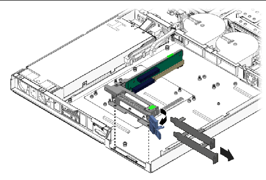
1. If necessary, remove the riser card filler panel. See FIGURE 4-6
FIGURE 4-6 Removing the PCIe Riser Card Filler Panels
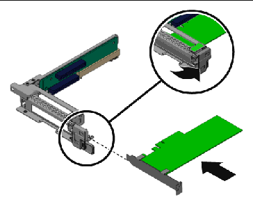
2. Insert the new PCIe card into the riser assembly and fasten the latch to secure it.
FIGURE 4-7 Installing a PCIe Card
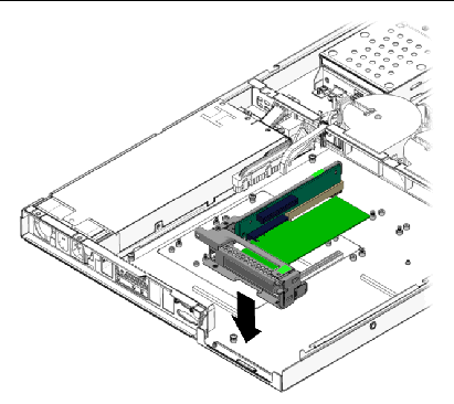
3. Reinstall the riser assembly into the connector on the motherboard.
FIGURE 4-8 Installing the PCIe Card Riser Assembly
4. Check the routing of all cables for obstructions, and then reinstall the cover.
The following procedures describe how to remove and install a hard disk drive (HDD) and carrier.
|
1. If you are not using an integrated-mirroring (IM) configuration, you must power off the server before removing an HDD; it is not necessary to remove the cover. Power off the system as described in Section 4.3, Powering Off the Server and Removing the Cover.
If you are using an IM configuration, start with Step 2.
2. Squeeze the release latch and carefully swing the arm to the left as far as it will go.
FIGURE 4-9 Removing a Hard Disk Drive
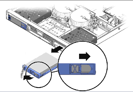
3. Grasp the carrier bezel with both hands and carefully pull the carrier out of the drive bay.
| Note - Avoid using the arm to remove the carrier. |
4. Reinsert the HDD and carrier into the server as described in Section 4.4.3, Replacing a Hard Disk Drive and Carrier.
|
1. Squeeze the release latch and carefully swing the arm to the left as far as it will go.
FIGURE 4-10 Installing the Hard Disk Drive
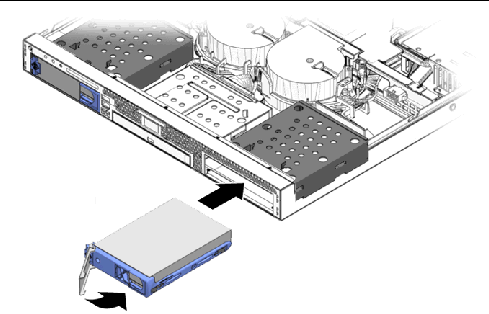
2. Grasping the body of the drive in both hands, carefully guide the connector end of the carrier into the drive bay, sliding the carrier into the bay until the arm engages and partially closes itself.
3. Push the arm forward and latch it to lock the carrier in place.
This section contains instructions on installing an LSI PCIe card. This card enables the following added functionality for the Sun Fire X2200 M2 server:
Use the appropriate procedure, depending on the hard drive format that you are using:
If your system originally had SATA drives installed or came diskless, and you would like to install SAS drives, use the following procedure.
You will need to order the following components needed for the SAS drive installation:
The following procedure describes how to remove the current SATA installation and install the SAS components. If you started with a diskless system, you do not need to do Step 2.
|
|
1. Power off the system and remove the cover as described in Section 4.3, Powering Off the Server and Removing the Cover.
2. Remove the current SATA hard drive(s) from the server, if necessary.
See Section 4.4.3, Replacing a Hard Disk Drive and Carrier.
3. Remove the cables currently connected to the HDD backplanes and motherboard connectors. See FIGURE 4-38 for the locations of the cables.
4. Install the new cables from the SAS cable kit. See FIGURE 4-11.
Note the following guidelines for installation:
FIGURE 4-11 SAS Drive Cable Routing
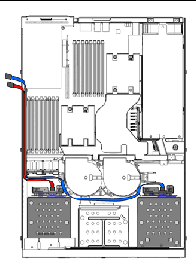
5. Remove the riser assembly from the server.
See To Remove the Riser Assembly and PCIe Card..
6. Install the LSI PCIe card into the riser assembly.
Do not install the riser card into the server yet. It will be easier to connect the cables with the card outside of the system.
7. Connect the SAS cables to the SAS card connectors. See FIGURE 4-12.
FIGURE 4-12 Installing an LSI PCIe Card
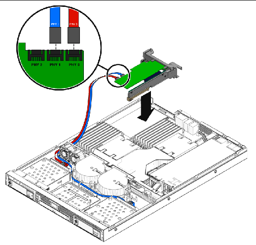
8. Install the riser assembly into the server.
See To Install the PCIe Card and Riser Card Assembly.
10. Install the SAS hard drives
See Section 4.4.3, Replacing a Hard Disk Drive and Carrier.
This section describes how to add the LSI PCIe card and cables to a system using SATA hard disks. The LSI card will support SATA hard disks attached to it. This configuration will only be used for customers who require a true SATA RAID configuration. You will need to order the following components:
The following procedure describes how to add the LSI PCIe card and cables to connect to the SATA hard disks.
1. Power off the system and remove the cover as described in Section 4.3, Powering Off the Server and Removing the Cover.
2. Remove the cables currently connected to the HDD backplanes and motherboard connectors.
See FIGURE 4-38 for the locations of the cables.
3. Install the new cables from the SAS cable kit. See FIGURE 4-13.
Note the following guidelines for installation:
FIGURE 4-13 SATA Drive Cable Routing
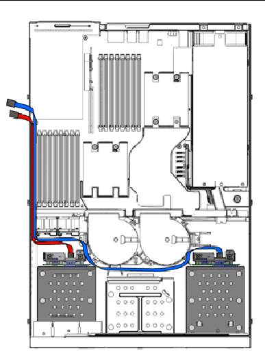
4. Remove the riser assembly from the server.
See To Remove the Riser Assembly and PCIe Card..
5. Install the LSI PCIe card into the riser assembly.
| Note - Do not install the riser card into the server yet. It will be easier to connect the cables with the card outside of the system. |
6. Connect the SATA cables to the LSI PCIe card connectors. See FIGURE 4-14.
FIGURE 4-14 Installing an LSI PCIe Card
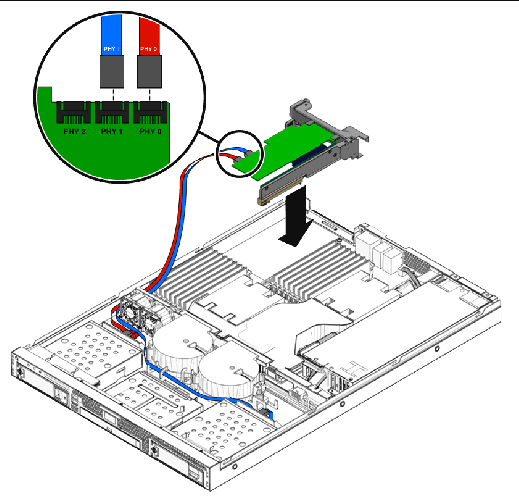
7. Install the riser assembly into the server.
See To Install the PCIe Card and Riser Card Assembly.
9. Install the SATA hard drives, if necessary.
See Section 4.4.3, Replacing a Hard Disk Drive and Carrier.
The following procedure describes how to remove and install the optical disk drive (ODD) assembly. If you are not replacing a DVD drive, go straight to Section 4.4.3, Replacing a Hard Disk Drive and Carrier.
|
1. Power off the system and remove the cover as described in Section 4.3, Powering Off the Server and Removing the Cover.
2. Unfasten the drive ribbon cable from the ODD drive.

|
Caution - Use care with the small flat cables. They are extremely fragile. |
FIGURE 4-15 Removing the DVD Drive Assembly
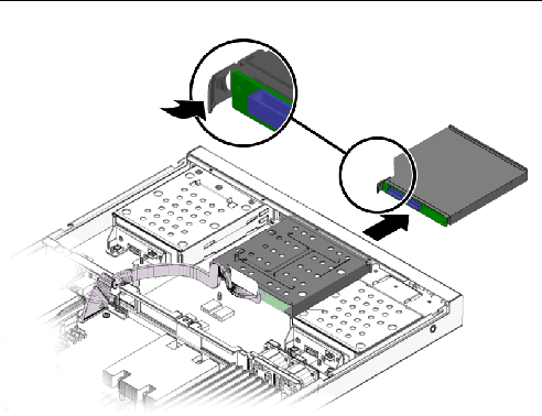
3. Push the latch on the back of the ODD drive toward the drive until the ODD drive springs forward out of the chassis.
4. Pull the ODD drive out the front of the chassis.

|
Caution - Move the assembly by grasping it by its sides. Do not push on the
DVD-ROM tray. |
|
1. If necessary, remove the filler panel in front of the ODD drive slot on the front panel.
Put your finger or a screw driver behind the slot on the right side of the filler panel and pull the panel outward.
FIGURE 4-16 Removing the DVD Filler Panel
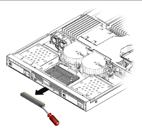
2. Position the ODD drive in front of the ODD drive slot on the front panel.
3. Push the ODD drive into the drive slot until the drive clicks into place.
FIGURE 4-17 Installing the DVD Drive Assembly
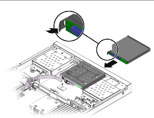
4. Reinstall the ODD drive cable.
5. Check the routing of all cables for obstructions, and then reinstall the cover.
The following procedures describe how to remove and install the system air duct.
|
1. Power off the system and remove the cover as described in Section 4.3, Powering Off the Server and Removing the Cover.
2. Remove the screw fastening the air duct to the chassis divider.
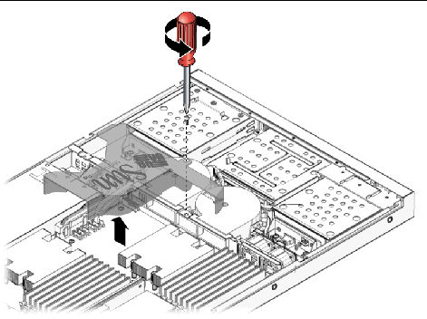
|
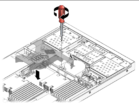
1. Position the air duct as shown in FIGURE 4-19, aligning the baffle with the screw hole and opening in chassis divider.
2. Fasten the screw that attaches the air duct to the chassis divider.
FIGURE 4-19 Air Duct Installation
The following procedures describe how to remove and install the power supply.
|
1. Power off the system and remove the cover as described in Section 4.3, Powering Off the Server and Removing the Cover.
2. Remove the air duct. See Section 4.4.6, Replacing an Air Duct.
3. Disconnect the two power supply cables from the motherboard and power supply connections to the hard drives.
4. Remove the bracket with the captive screw.
FIGURE 4-20 Removing the Power Supply
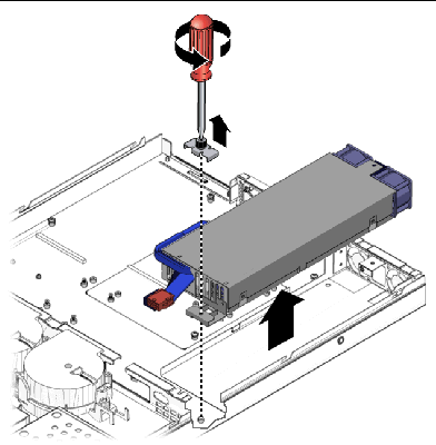
6. Lift the power supply out of the chassis.
|
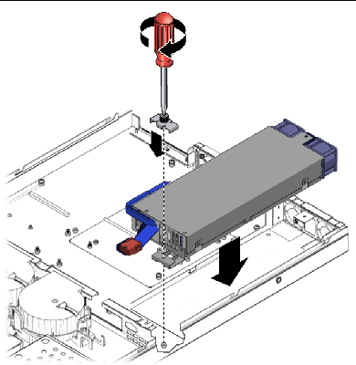
1. Position the power supply over the chassis power-supply cage.
2. Insert the power supply into the chassis and push it forward so that it is flush with the back panel.
3. Install the power supply bracket on top of the power supply tab and fasten the captive screw.
FIGURE 4-21 Installing the Power Supply
4. Connect two of the power supply cables to the motherboard and one cable to the SATA backplanes. See FIGURE 4-38.
5. Replace the air duct. See Section 4.4.6, Replacing an Air Duct.
6. Check the routing of all cables for obstructions, and then reinstall the cover.
The following procedures describe how to remove and install a single system fan module.
|
1. Power off the system and remove the cover as described in Section 4.3, Powering Off the Server and Removing the Cover.
2. Identify the fan to be replaced.
3. Pull the fan upward to remove it.
FIGURE 4-22 Removing a Fan Module
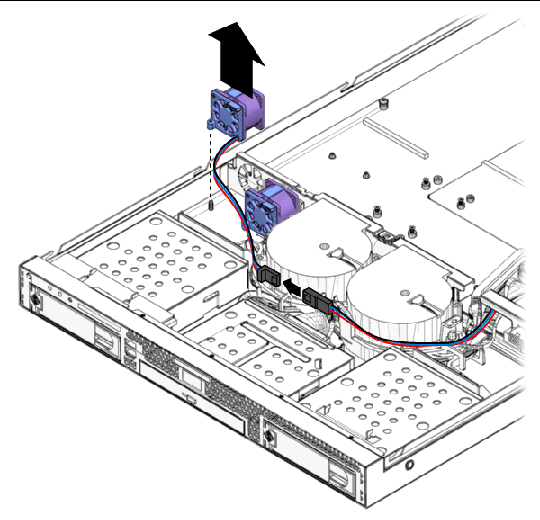
4. Unplug the fan’s power connector from the connector on the fan harness.
| Note - Note exactly which motherboard connector to which the fan was connected. If you connect a fan to an incorrect connector, the SP cannot correctly identify a fan failure. |
|
1. Position the fan so that the arrow on top of the fan casing is facing the middle chassis divider.
2. Place the fan in the chassis so that it fits over the small guideposts.
FIGURE 4-23 Installing a Fan Module
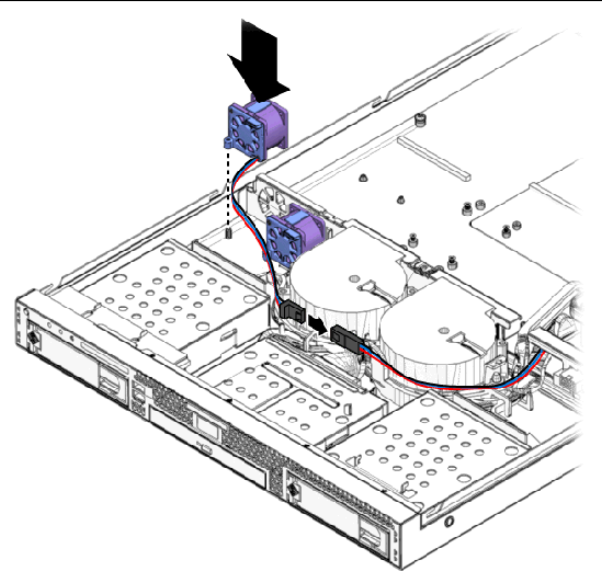
3. Gently push the fan down to secure it to the chassis.
4. Connect the fan connector to the appropriate connector on the fan harness.
5. Check the routing of all cables for obstructions, and then reinstall the cover.
The following procedures describe how to remove and install a dual blower module.
|
1. Power off the system and remove the cover as described in Section 4.3, Powering Off the Server and Removing the Cover.
2. Remove the single fan connectors from the harness connectors.
Note exactly which motherboard connector to which the fan was connected. If you connect a fan to an incorrect connector, the SP cannot correctly identify a fan failure.
3. Push in the green tabs on both sides of the dual blower module and simultaneously pull the fan module upward to remove it.
FIGURE 4-24 Removing a Dual Blower Module
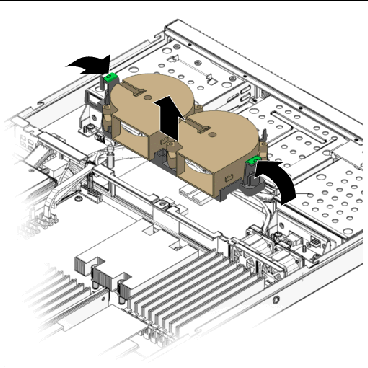
4. Unplug the fan’s power connector from the motherboard.
|
1. Position the dual fan module so that it fits over the guideposts and the duct opening fits into the cutouts in the chassis divider.
FIGURE 4-25 Installing a Dual Blower Module
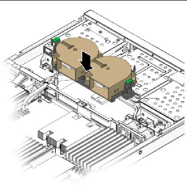
2. Gently push the blower module down, until you hear the side tabs click into place.
3. Connect the blower connectors to the appropriate connector on the motherboard.
4. Connect each of the single fan connectors to the corresponding fan harness connector.
5. Route the cables through the wiring retainers on the blower module.
6. Check the routing of all cables for obstructions, and then reinstall the cover.
| Note - Keep in mind the following information and rules when you use the procedures in this section to replace or add DIMMs to the server. |
The following procedure describes how to remove and install dual inline memory modules (DIMMs).
|
1. Power off the system and remove the cover as described in Section 4.3, Powering Off the Server and Removing the Cover.
2. Locate the DIMM connector in which you will remove and install a memory module.
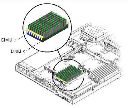
If your system has a dual-CPU configuration, it will have two banks of DIMMs. Bank 0 is the bank closest to CPU 0 and Bank 1 is the bank closest to CPU 1. See FIGURE 4-27 and FIGURE 4-26.
FIGURE 4-26 Bank 0 DIMM Slot Locations
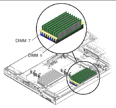
FIGURE 4-27 Bank 1 DIMM Slot Locations
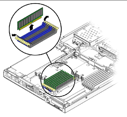
3. Remove a DIMM by pressing down on the ejector bars at both ends of the memory module’s socket (see FIGURE 4-28).
|
1. Refer to Section , The following procedure describes how to remove and install dual inline memory modules (DIMMs). before installing DIMMs.
2. Ensure that the DIMM socket ejectors are open (rotated outward) to allow the new module to be inserted.
3. Align the DIMM’s edge connector with the alignment key and insert the memory module into the connector.
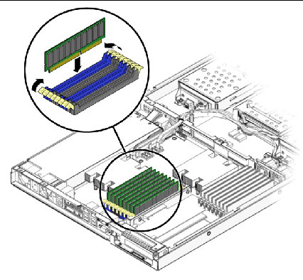
4. Using both thumbs, press the DIMM straight down into the DIMM slot until both ejector levers click, locking the DIMM in the DIMM slot.
| Note - The manufacturer and capacity of both modules in the same memory bank
(Banks 1-4) must be identical. |
5. Check the routing of all cables for obstructions, and then reinstall the cover.
The system battery is a common CR2032 calculator battery.
You might need to replace the system battery if you know it is weak or if after any period of AC power loss, the BIOS loses its CMOS settings, or if the time-of-day clock loses time.

|
Caution - Do not attempt to open or service batteries. The battery contains lithium and can explode if not properly used, handled, or disposed of. |
|
1. Power off the system and remove the cover as described in Section 4.3, Powering Off the Server and Removing the Cover.
2. Remove the air duct as shown in Section 4.4.6, Replacing an Air Duct.
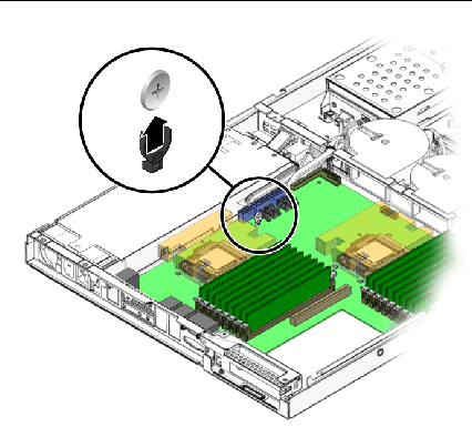
3. Remove the system battery by pulling it up and out of the holder (see FIGURE 4-30 for the location).
FIGURE 4-30 Removing the System Battery
|
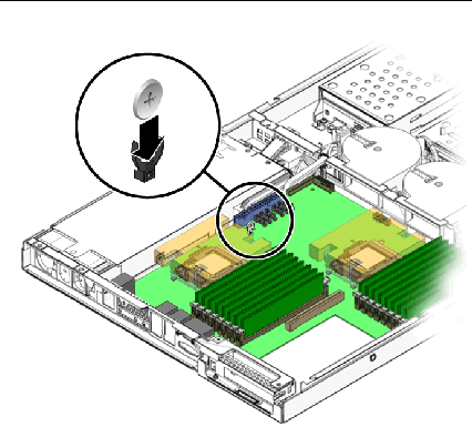
1. Insert the new system battery into the holder with the side labeled “+” facing away from the power supply.
FIGURE 4-31 Installing the System Battery
| Note - Replace the battery only with the identical model. |
2. Check the routing of all cables for obstructions.
3. Reinstall the air baffle as shown in Section 4.4.6, Replacing an Air Duct.
The following procedure describes how to remove and install a CPU. The Sun Fire X2200 M2 server supports both single- and dual-CPU configurations.
| Note - Replacement of a CPU and heatsink should only be done by trained service personnel. If you are adding a second CPU to a single CPU configuration, see Section 4.4.13, Replacing a CPU and Heatsink. |

|
Caution - Observe the appropriate ESD precautions in Section 4.2.1, ESD Precautionswhen handling the CPU. |
|
1. Power off the system and remove the cover as described in Section 4.3, Powering Off the Server and Removing the Cover.
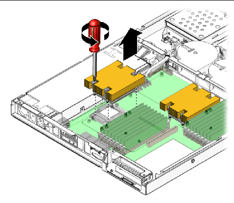
2. Unfasten the four screws securing the heatsink to the board (see FIGURE 4-32).
FIGURE 4-32 Removing the Heatsink

|
Caution - The heatsink can become extremely hot. Be sure it has had sufficient time to cool before handling. |
3. Twist the heatsink slightly to the right or left to break the seal with the thermal grease.
4. Lift the heatsink away from the CPU.
5. Place the heatsink upside-down on a flat surface to prevent the thermal grease from contaminating other components.
6. Pull the socket release lever up to the fully open, perpendicular position.
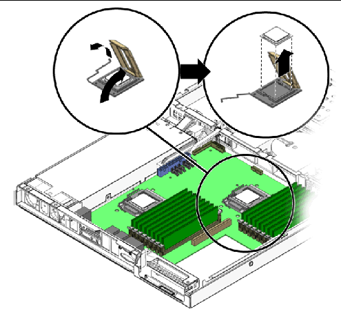
8. Lift the CPU out of the socket, leaving the release lever in the open position.
| Note - Ensure that no thermal grease that might be left from the heatsink comes into contact with the CPU socket or underside of the CPU chip. |
|
| Note - Follow these steps to install a CPU and heatsink if you are replacing a CPU. If you want to install a new CPU, see Section 4.4.13, Replacing a CPU and Heatsink. |

|
Caution - Observe the appropriate ESD precautions in Section 4.2.1, ESD Precautionswhen handling the CPU. |
2. If you are installing a second CPU into a formerly single-CPU system, you will need to remove the socket cover before installing the new CPU
3. Ensure that the socket release lever is in the fully open, perpendicular position and the CPU cover is open (see FIGURE 4-34).
4. Align the small triangle, on the upper left corner of the CPU, with the triangle on the corner of the socket.
FIGURE 4-34 Installing the CPU
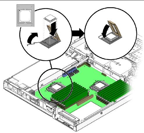
5. Insert the CPU into the socket.
6. When the CPU is fully seated in the socket, close the CPU cover.
7. Rotate the socket release lever down until it snaps into place, securing the CPU in the socket.
8. Use the syringe to apply approximately 0.1 ML/CC of thermal grease in a circular pattern to the top of the CPU.
9. Gently distribute the thermal grease and remove any excess so that only an extremely thin, uniform layer remains. If any voids or crevices appear that could lead to air pockets, reapply the grease until you achieve a thin but compact consistency.
10. Use an alcohol pad to remove all thermal grease from the bottom of the heatsink.
11. Inspect the heatsink for dust and lint. Clean if necessary.
12. Carefully position the heatsink on the CPU, aligning it with the mounting posts to reduce movement after it makes initial contact with the layer of thermal grease.

|
Caution - If the heatsink is moved too much during its installation, the layer of thermal grease may become uneven, leading to component damage. |
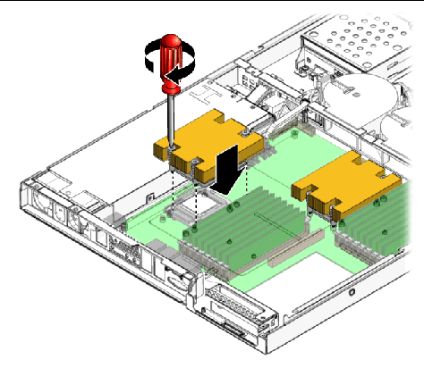
13. Fasten the four screws attaching the heatsink to the motherboard. See FIGURE 4-35.
FIGURE 4-35 Installing the Heatsink
|
| Note - Replacement of a CPU and heatsink should only be done by trained service personnel. If you are replacing an already installed CPU, rather than adding a new one, follow the instructions in Section 4.4.13, Replacing a CPU and Heatsink. |

|
Caution - Observe the appropriate ESD precautions in Section 4.2.1, ESD Precautionswhen handling the CPU. |
2. If you are installing a second CPU into a formerly single-CPU system, you will need to remove the socket cover before installing the new CPU.
3. Ensure that the socket release lever is in the fully open, perpendicular position and the CPU cover is open (see FIGURE 4-34).
4. Align the small triangle, on the top left corner of the CPU, with the triangle on the corner of the socket.
FIGURE 4-36 Installing the CPU
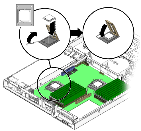
5. Insert the CPU into the socket.
6. When the CPU is fully seated in the socket, close the CPU cover.
7. Rotate the socket release lever down until it snaps into place, securing the CPU in the socket.
8. Inspect the heatsink for dust and lint. Clean if necessary.
9. Carefully position the heatsink on the CPU, aligning it with the mounting posts to reduce movement after it makes initial contact with the layer of thermal grease.

|
Caution - If the heatsink is moved too much during its installation, the layer of thermal grease may become uneven, leading to component damage. |
10. Fasten the four screws attaching the heatsink to the motherboard. See FIGURE 4-37.
FIGURE 4-37 Installing the Heatsink
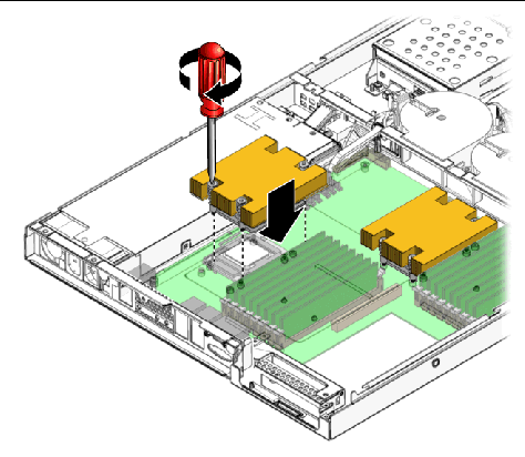
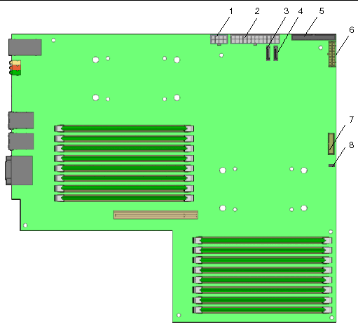
FIGURE 4-38 and show the routing of the cables and motherboard connector locations.
FIGURE 4-38 Cable Routing Diagram
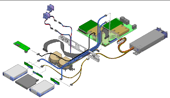
The following table describes the cables that are included with the associated component replacement kits.
The following procedures describe how to remove and install the Sun Fire X2200 M2 server system motherboard.
| Note - The motherboard is not a CRU and should be replaced only by trained field service technicians. |
|
1. Power off the system and remove the cover as described in Section 4.3, Powering Off the Server and Removing the Cover.
2. Remove the PCIe card riser assembly installed on the motherboard (see Section 4.4.2, Replacing the PCIe Card and Riser Assembly) and the air duct (see Section 4.4.6, Replacing an Air Duct).
3. Disconnect all cables attached to the motherboard.
4. Remove the four screws from the heatsink (4 screws per heatsink installed).
| Note - Do not remove the screws that secure the CPU heatsink assemblies mounting to the motherboard. |
5. Remove the seven Phillips screws that fasten the motherboard to the chassis with a Phillips screwdriver.
6. Remove the screws attaching the serial connector to the chassis with a 5 mm nut driver.
FIGURE 4-39 Removing the Motherboard
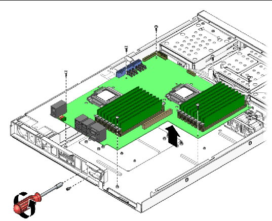
7. Pull the motherboard away from the chassis.
8. Remove the CPU and memory modules.
Refer to the following sections for information on removing and replacing the CPU and memory:
|

|
Caution - Observe proper ESD precautions in Section 4.2.1, ESD Precautionswhen handling the new motherboard. |
1. Center the motherboard on the chassis so that the screw holes in the motherboard align with the screw holes on the chassis.
2. Secure the seven Phillips screws that fasten the motherboard to the chassis. Torque screws to 8- to 9-inch pounds.
3. Secure the screws attaching the serial connector to the chassis with a 5 mm nut driver.
FIGURE 4-40 Installing the Motherboard
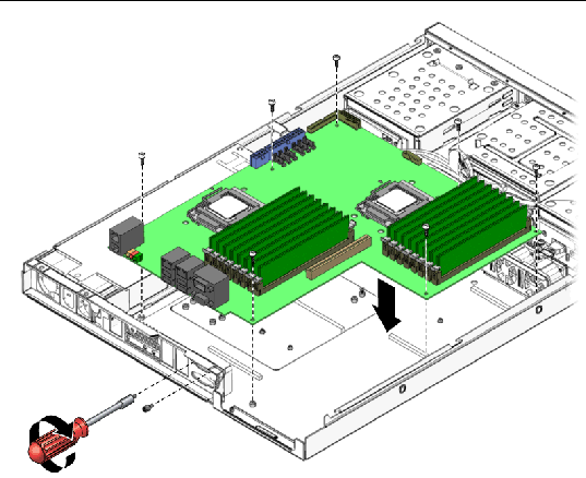
4. Replace the CPU and DIMMs as necessary.
Refer to the following sections for information on removing and replacing the CPU and memory:
5. Replace the PCIe card riser assembly and air baffle.
6. Reconnect all internal system cables.
Section 4.4.14, Replacing Cables.
8. Replace any external cables and power on the server.
The following procedure describes how to remove and install the system firmware PROM.
The firmware PROM is located at the rear of the server. Access to the firmware PROM is obstructed by the PCI riser assembly. To replace the firmware PROM, you must first remove the PCI riser assembly.
To perform this procedure, you must have the following:
1. Power off the system and remove the cover as described in Section 4.3, Powering Off the Server and Removing the Cover.
| Note - If a PCI card is installed in the riser assembly, you do not need to remove the card first to perform this procedure. |
2. Remove the PCIe riser assembly installed on the motherboard (see Section 4.4.2, Replacing the PCIe Card and Riser Assembly) and the air duct (see Section 4.4.6, Replacing an Air Duct).
3. Set the PCI riser assembly next to the server.
4. Insert the ends of the PLCC extraction tool into the elongated corner slots on the firmware PROM socket (see FIGURE 4-41).
FIGURE 4-41 Location of the Firmware PROM and Use of the PLCC Extractor Tool
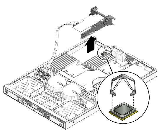
5. To remove the firmware PROM, gently squeeze the extraction tool.
This action pulls the PROM from the socket.
6. Remove the PROM from the server.
There is only one way to install the firmware PROM chip into the socket. The PROM chip has three right-angle corners. The fourth corner, on the beveled edge side of the firmware PROM chip, is trimmed at 45 degrees. One of the outer-edge corners of the PROM socket on the motherboard is trimmed the same way, and the same interior corner of the PROM socket has a semi-circular protrusion. This is the key to proper installation (see FIGURE 4-42). To install the firmware PROM chip properly, the trimmed corner of the chip must align with the corner of the PROM socket with the semi-circular protrusion.
1. Remove the new firmware PROM chip from the anti-static packaging.
Handle the chip carefully. Avoid touching the metal contacts.
2. Align the trimmed corner of the PROM chip with the keyed corner of the socket.
The trimmed corner of the chip, when properly seated in the socket, must align with the socket corner that has the semi-circular protrusion (see FIGURE 4-42).
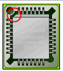
3. When properly aligned, place the PROM chip on top of the socket.
4. Using your finger or thumb, gently push the firmware PROM chip downward into the socket until the top of the chip is flush with the top of the socket.
The new firmware PROM chip is now installed.
5. Clear the CMOS. See Section 1.5, Clearing the CMOS.
6. Update the BIOS and SP firmware. See Section B.2, Updating BIOS and BMC Firmware.
Copyright © 2008, Sun Microsystems, Inc. All Rights Reserved.