| Sun Fire X4140 Server Service Manual |
| C H A P T E R 4 |
|
Servicing Motherboard Components |
This chapter describes how to replace the motherboard and its components in the Sun Fire X4140 Server.
| Note - Before performing any of the procedures in this chapter, perform the procedures described in Chapter 2, Preparing to Service the System. |
The following topics are covered in this chapter:

|
Caution - Never attempt to run the server with the covers removed. Hazardous voltage present. |
|
|
Caution - Equipment damage possible. The covers must be in place for proper air flow. |
This section describes how to diagnose and replace faulty DDR2 DIMMs (DDR2 DIMMs). The following topics are covered:
| Note - CRU: This customer-replaceable unit can be replaced by anyone. |

|
Caution - This procedure requires that you handle components that are sensitive to static discharge. This sensitivity can cause the component to fail. To avoid damage, ensure that you follow antistatic practices as described in Performing Electrostatic Discharge and Antistatic Prevention Measures. |
The Sun Fire X4140 Server Service Required LED is lit if the system detects a DDR2 DIMM fault.
To use the rear panel Locator button to identify faulty DDR2 DIMMs:
1. Unplug all power cords from the rear panel.
2. Press the remind button (FIGURE 4-1).
3. Note the location of faulty DDR2 DIMMs.
Faulty DDR2 DIMMs are identified with a corresponding amber LED on the motherboard.
4. Ensure that all DDR2 DIMMs are seated correctly in their slots. If re-seating the DIMM does not fix the problem, remove and replace the faulty DIMM.
| Note - Refer to the Sun Fire X4140, X4240, and X4440 Servers Diagnostics Guide for more information about DIMM System Event Log (SEL) messages. |

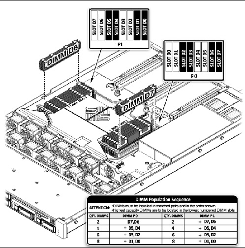
Use the DDR2 DIMM guidelines, and FIGURE 4-2 to help you plan the memory configuration of your server.
Any even number of DIMMs is allowed. The DIMMs must be populated in pairs and the pairs must be identical in organization, size and speed. See FIGURE 4-2 for detailed configuration information.
Refer to the service label on the cover for DDR2 DIMM placement information. Refer to the Sun Fire X4140, X4240, and X4440 Servers Diagnostics Guide for additional DDR2 DIMM information.
Type the following in ILOM to view the memory configuration.
/SYS/MB/P0/D0
   Targets:
       SERVICE

   Properties:
       type = DIMM
       fru_name = 2048MB DDR-II 666
       fru_manufacturer = Hynix Semiconductor Inc.
       fru_version = 4141
       fru_part_number = HYMP525P72CP4-Y5
       fru_serial_number = 00005092
Commands:
       cd
       show
->
| Note - DDR2 DIMM names in Integrated LOM messages are displayed with the full name, such as /SYS/MB/DIMM_D0. |
If a one processor configuration is ordered, the DDR2 DIMM physical memory layout requires that all memory must be located next to the installed processor, working from the outside in. Do not install memory on the side that does not have a processor installed.
|
|
Caution - Ensure that all power is removed from the server before removing or installing DDR2 DIMMs. You must disconnect the power cables before performing this procedure. |
1. Review DDR2 DIMM Guidelines for memory configuration information.
2. Prepare the server for service.
b. Disconnect the power cord (or cords) from the power supply (or supplies).
c. Extend the server into the maintenance position.
See Extending the Server to the Maintenance Position.
d. Attach an antistatic wrist strap.
See Performing Electrostatic Discharge and Antistatic Prevention Measures.
3. If you are replacing a faulty DDR2 DIMM, press the “Remind” button to activate the DDR2 DIMM status LEDs after power is removed.
All faulty DDR2 DIMMs are indicated with an amber LED on the motherboard, so that you can install the replacement DDR2 DIMM in the same location.
| Tip - Make a note of the faulty DDR2 DIMM location. |
4. Push down on the ejector tabs on each side of the DDR2 DIMM until the FB-DIMM is released (FIGURE 4-3).
5. Grasp the top corners of the faulty DDR2 DIMM and remove it from the server.
FIGURE 4-3 Removing DDR2 DIMMs

6. Place the DDR2 DIMM on an antistatic mat.
7. Repeat Step 4 through Step 6 to remove any additional DDR2 DIMMs.
| Tip - See DDR2 DIMM Guidelines for information about configuring the DDR2 DIMMs. |
1. Unpackage the replacement DDR2 DIMMs and place them on an antistatic mat.
2. Ensure that the ejector tabs are in the open position.
3. Line up the replacement DDR2 DIMM with the connector (FIGURE 4-4).
Align the DDR2 DIMM notch with the key in the connector. This ensures that the DDR2 DIMM is oriented correctly.
4. Push the DDR2 DIMM into the connector until the ejector tabs lock the DDR2 DIMM in place.
If the DDR2 DIMM does not easily seat into the connector, verify that the orientation of the DDR2 DIMM is as shown in FIGURE 4-4. If the orientation is reversed, damage to the DDR2 DIMM might occur.
5. Repeat Step 2 through Step 4 until all replacement DDR2 DIMMs are installed.
7. Slide the server into the rack.
See Returning the Server to the Normal Rack Position.
8. Reconnect the power cord (or cords) to the power supply (or supplies).
Verify that the AC Present LED is lit.
FIGURE 4-4 Installing DDR2 DIMMs

Before you begin, see DDR2 DIMM Guidelines, for information about DDR2 DIMM configuration guidelines.
1. Unpackage the replacement DDR2 DIMMs and place them on an antistatic mat.
2. Ensure that the ejector tabs are in the open position.
3. Line up the DDR2 DIMM with the connector (FIGURE 4-4).
Align the DDR2 DIMM notch with the key in the connector. This ensures that the DDR2 DIMM is oriented correctly.
4. Push the DDR2 DIMM into the connector until the ejector tabs lock the DDR2 DIMM in place.
If the DDR2 DIMM does not easily seat into the connector, verify that the orientation of the DDR2 DIMM is as shown in FIGURE 4-4. If the orientation is reversed, damage to the DDR2 DIMM might occur.
5. Repeat Step 2 through Step 4 until all DDR2 DIMMs are installed.
6. Return the server to operation.
b. Slide the server into the rack.
See Returning the Server to the Normal Rack Position.
c. Reconnect the power cord (or cords) to the power supply (or supplies).
Verify that the AC Present LED is lit.
The following topics are covered:
You must remove the air baffle when removing and installing the motherboard.
| Note - CRU: This customer-replaceable unit can be replaced by anyone. |
|
|
Caution - To prevent the system from overheating, ensure that the air baffle is correctly installed before powering on the server. |
1. Prepare the server for service.
b. Disconnect the power cord (or cords) from the power supply (or supplies).
c. Slide the server out of the rack.
See Extending the Server to the Maintenance Position.
d. Attach an antistatic wrist strap.
See Performing Electrostatic Discharge and Antistatic Prevention Measures.
Slide the duct off of the screws and remove the air baffle as shown in FIGURE 4-5.
FIGURE 4-5 Removing the Air Baffle
.")
|
|
Caution - When the server is in operation, ensure that the air baffle is correctly installed to prevent the system from overheating. |
1. Install the air baffle into the chassis as shown in FIGURE 4-6.
Ensure that the air baffle is aligned and fully seated in the chassis.
2. Return the server to operation.
b. Slide the server into the rack.
See Returning the Server to the Normal Rack Position.
c. Reconnect the power cord (or cords) to the power supply (or supplies).
Verify that the AC Present LED is lit.
FIGURE 4-6 Installing the Air Baffle
.")
The following topics are covered:
PCIe cards are installed on vertical risers. You must remove the relevant riser to access a PCIe card. You must remove all three PCIe risers when replacing the motherboard.
| Note - CRU: This customer-replaceable unit can be replaced by anyone. |
|
|
Caution - This procedure requires that you handle components that are sensitive to static discharge. This sensitivity can cause the component to fail. To avoid damage, ensure that you follow antistatic practices as described in Performing Electrostatic Discharge and Antistatic Prevention Measures. |
|
|
Caution - Ensure that all power is removed from the server before removing or installing risers. You must disconnect the power cables before performing this procedure. |
1. Prepare the server for service.
b. Disconnect the power cord (or cords) from the power supply (or supplies).
c. Attach an antistatic wrist strap.
See Performing Electrostatic Discharge and Antistatic Prevention Measures.
2. Disconnect any data cables connected to the cards on the PCIe riser being removed.
Label the cables to ensure proper connection later.
3. Slide the server out of the rack.
See Extending the Server to the Maintenance Position.
4. If you are servicing a PCIe card, locate its position in the system.
5. Remove the rear panel crossbar.
a. Loosen the captive Phillips screw on each end of the rear panel crossbar.
b. Lift the crossbar up and back to remove it from the chassis.
6. Lift the riser up to remove it from the system (FIGURE 4-7).
a. Loosen the captive Phillips screw on the end of the riser.
b. Remove the riser and any PCIe cards attached to it as a unit.
FIGURE 4-7 Removing a PCIe Riser
.")
|
|
Caution - Ensure that all power is removed from the server before removing or installing risers. You must disconnect the power cables before performing this procedure. |
1. Lower the PCIe riser and any cards attached to it into the system.
2. Slide the back of the riser into the motherboard rear panel stiffener.
3. Install the screw that secures the riser to the motherboard (FIGURE 4-8).
4. Install the rear panel crossbar.
Slide the crossbeam down over the PCIe risers. The crossbar is secured with two captive Phillips screws.
5. Slide the server into the rack. See Returning the Server to the Normal Rack Position.
6. Connect any data cables you removed to service the PCIe cards.
7. Reconnect the power cord (or cords) to the power supply (or supplies).
Verify that the AC Present LED is lit.
FIGURE 4-8 Installing a PCIe Riser
.")
The following topics are covered:
| Note - CRU: This customer-replaceable unit can be replaced by anyone. |
|
|
Caution - This procedure requires that you handle components that are sensitive to static discharge. This sensitivity can cause the component to fail. To avoid damage, ensure that you follow antistatic practices as described in Performing Electrostatic Discharge and Antistatic Prevention Measures. |
|
|
Caution - Ensure that all power is removed from the server before removing or installing expansion cards. You must disconnect the power cables before performing this procedure. |
The PCI expansion system is configured using two types of riser cards.
Riser type 1 is used in the Riser 0 and Riser 1 positions and Riser type 2 is used in the slot 2 position as shown in TABLE 4-1. The electrical width is the number of active PCIe lanes and the mechanical width describes the riser PCIe connector size. PCIe cards with x4, x8 or x16 mechanical finger pins will fit in any riser slot but will operate at the electrical lane width of the slot.
The SGXPCIESAS-R-INT-Z HBA should be installed in slot 0 to avoid system overheating. Make sure that the firmware is at SW 3.1 or later when installing the HBA in Slot 0.
|
|
Caution - Ensure that all power is removed from the server before removing or installing expansion cards. You must disconnect the power cables before performing this procedure. |
1. Locate the PCIe card that you want to remove, and note its corresponding riser board.
See Sun Fire X4140 Server Rear Panel Features for more information about PCIe slots and their locations.
2. If necessary, make a note of where the PCIe cards are installed.
3. Unplug all data cables from the card.
Note the location of all cables for reinstallation later.
4. Remove the riser board (FIGURE 4-9).
5. Carefully remove the PCIe card from the riser board connector.
6. Place the PCIe card on an antistatic mat.
7. If you are not replacing the PCIe card, install a PCIe filler panel.
PCIe filler panels are located in the motherboard rear panel.
FIGURE 4-9 Removing a PCIe Card
.")
1. Unpackage the replacement PCIe card and place it on an antistatic mat.
2. Locate the proper PCIe slot for the card you are replacing.
3. If necessary, review the PCIe Card Guidelines to plan your installation.
See Sun Fire X4140 Server PCIe Card Guidelines for additional information.
4. Remove the PCIe riser board.
5. If the server has been continuously used for an extended time, inspect the slot for particles.
Clean the slot with filtered, compressed air, as required.
6. Remove the PCI filler panel.
PCIe filler panels are located in the motherboard rear panel.
7. Insert the PCIe card into the correct slot on the riser board (FIGURE 4-10).
a. Slide the riser back until it seats in its slot in the rear panel.
b. Tighten the captive No. 2 Phillips screw securing the riser to the motherboard.
9. Return the server to operation.
b. Slide the server into the rack.
See Returning the Server to the Normal Rack Position.
c. Connect any data cables required to the PCIe card.
Route data cables through the cable management arm.
d. Reconnect the power cord (or cords) to the power supply (or supplies).
Verify that the AC Present LED is lit.
FIGURE 4-10 Installing a PCIe Card
.")
The following topics are covered:
The battery maintains system time when the server is powered off and a time server is unavailable. If the server fails to maintain the proper time when powered off and not connected to a network, replace the battery.
You need a small (No. 1 flat-blade) screwdriver.
| Note - CRU: This customer-replaceable unit can be replaced by anyone. |
|
|
Caution - Ensure that all power is removed from the server before removing or installing the battery. You must disconnect the power cables from the system before performing this procedure. |

See Sun Fire X4140 Server PCIe Card Guidelines.
2. Using a small (No. 1 flat-blade) screwdriver, press the latch and remove the battery from the motherboard.
1. Unpackage the replacement battery.
2. Press the new battery into the motherboard.
Install the positive side (+) facing upward, away from the motherboard.
4. Use the ILOM command to set the day and time. Type:
-> set /SP/clock datetime=MMDDhhmmYYYY (or MMDDhhmmYYYY.ss)
This section describes the following procedures:
You must remove the motherboard assembly to access the following components:
| Note - FRU: This field-replaceable unit should be replaced only by qualified service technicians. Contact your Sun Service representative for assistance. |
|
|
Caution - This procedure requires that you handle components that are sensitive to electrostatic discharge. This discharge can cause server components to fail. To avoid damage, ensure that you follow the antistatic practices as described in Performing Electrostatic Discharge and Antistatic Prevention Measures. |
|
|
Caution - This procedure requires removing the server from the rack. The server is heavy. Two people are required to remove it from the rack. |
1. Prepare the server for service.
b. Disconnect the power cord (or cords) from the power supply (or supplies).
c. Remove the server from the rack.
See Removing a Server From the Rack.
d. Extend the server into the maintenance position.
See Extending the Server to the Maintenance Position.
e. Attach an antistatic wrist strap.
See Performing Electrostatic Discharge and Antistatic Prevention Measures.
3. Remove the PCIe cards and risers.
See Removing a PCIe Riser. Make note of the location of expansion cards in the PCIe risers.
4. Disconnect the power distribution board ribbon cable.
5. If you are replacing the motherboard, remove the DDR2 DIMMs.
Make note of the memory configuration so that you can install the DDR2 DIMMs in the replacement motherboard.
6. Disconnect the drive data cables.
|
|
Caution - The drive data cables are delicate. Ensure they are safely out of the way when servicing the motherboard. |
7. Remove the processor heat sinks from the motherboard assembly.
8. Remove the 4 screws that secure the motherboard to the bus bar.
Use a No. 2 Phillips screwdriver.
9. Loosen the green captive screw on the front of the motherboard, that secures the motherboard tray to the chassis.
10. Remove the plastic air flow bezel from between the fans and the motherboard.
11. If you are replacing the motherboard only, remove the processors, as required.
12. Lift the motherboard assembly out of the chassis (FIGURE 4-12).
Move the motherboard carefully.
13. Place the motherboard assembly on an antistatic mat.
FIGURE 4-12 Removing the Motherboard Assembly
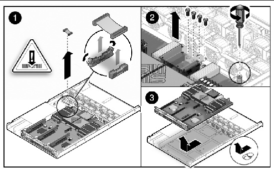
Figure showing how to remove a motherboard (Sun Fire X4140 Server).
|
|
Caution - This procedure requires that you handle components that are sensitive to static discharge. Static discharges can cause the component failures. To avoid damage, ensure that you follow antistatic practices as described in Performing Electrostatic Discharge and Antistatic Prevention Measures. |
2. Attach an antistatic wrist strap.
See Performing Electrostatic Discharge and Antistatic Prevention Measures.
3. Place the motherboard into the chassis (FIGURE 4-13).
Position the motherboard carefully.
FIGURE 4-13 Installing the Motherboard Assembly
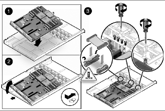
Figure showing how to install a motherboard (Sun Fire X4140 Server).
4. Install the 4 screws that secure the motherboard to the bus bar.
Torque screws to 7 inch-pounds (0.8 newton-meters). Use a manual torque driver settable to 7 inch-lbs (0.8 newton-meters) with a No. 2 Phillip screwdriver.
5. Tighten the green captive screw on the front of the motherboard, that secures the motherboard tray to the chassis.
6. If you are replacing the motherboard only, replace the processors, as required.
Apply thermal grease. You need the a thermal grease kit to replace the processors. Follow the applicable grease procedure included with the grease.
FIGURE 4-14 Required Pattern for Thermal Grease Application
.")
7. Install the plastic air flow bezel between the fans and the motherboard.
8. Install the processor heat sinks. See Installing a Processor FRU.
9. Carefully connect the power distribution board ribbon cable to the motherboard.
Make sure it is seated properly.
10. Connect the two drive data cables.
|
|
Caution - The drive data cables are delicate. Carefully connect them and make sure that they are seated properly when servicing the motherboard. |
11. Install all DDR2 DIMMs in the motherboard assembly.
| Note - Only install the DDR2 DIMMs in the slots (connectors) from which they were removed. See DDR2 DIMM Guidelines. |
See Installing the Air Baffle.
13. Reinstall the PCIe cards and risers.
14. Return the server to operation.
b. Install the server into the rack.
See Reinstalling the Server in the Rack.
c. Reconnect the power cord (or cords) to the power supply (or supplies).
Verify that the AC Present LED is lit.
15. After you replace the board FRU, use the servicetool command to update FRU information about the board. See Servicetool FRU Update Procedures.
The following topics are covered:
|
|
Caution - The SunService account is for the use of Sun service representatives only. Do not use the SunService account unless you are instructed to do so in a procedure developed by Sun Microsystems. |

| Note - Before beginning these procedures, obtain Service/Escalation passwords from the Customer Support Center. |
1. Use SSH to log into the SunService account. The default password is changeme.
# ssh <SP IP address> -l sunservice
# <SP IP Address>'s password: changeme
2. At the prompt, enter the servicetool command with options. The options are defined in the table below.
# servicetool --fru_update=serviceprocessor <OtherOptions>=<value>
3. Watch the output from the command and respond to the confirmation prompts for continuing the update and rebooting the server:
Servicetool is going to collect system information for the service processor for future part swaps.
The following preconditions must be true for this to work:
    * The new service processor must be installed.
Do you want to continue (y|n)? y
Service processor FRU information ready to be collected.
You MUST reboot the service processor for to complete
this process. Allow the service processor to fully boot.
DO NOT UNPLUG THE SYSTEM WHILE THE SERVICE PROCESSOR IS BOOTING!
Would you like to reboot the service processor now (y|n)? y
The system is going down NOW!!
Sending SIGTERM to all processes.
1. In Escalation mode in ILOM, view product information on the FRUID PROM that is on the Power Distribution Board (PDB) by issuing this command:
# frutool -t pb --read_cmm_product_area
product part_number 594-5133-03
product serial_number 0829QAS003
product asset_tag NULL:16
chassis serial_number 0226LHF-0822B402YH
chassis part_number 540-7618-XX
2. Save the entire motherboard FRUID image, in case it later needs to be restored to its original state:
# frutool -r mb > /persist/mb.bin
3. Copy the product information from the PDB to a file:
# frutool -t pb --read_cmm_product_area > /dev/shm/product.info
4. View the file by issuing the following command to verify the previous step was successful:
5. Write the product information to the motherboard by issuing this command:
# frutool -t mb --write_cmm_product_area < /dev/shm/product.info
6. View the file to ensure that the product data has been updated in the motherboard FRUID PROM:
# frutool -r mb | hexdump -C | egrep ’^000004’
00000400  00 00 00 00 00 00 00 00  00 00 00 00 00 a4 70 72  |..............pr|
00000410  6f 64 75 63 74 20 70 61  72 74 5f 6e 75 6d 62 65  |oduct part_numbe|
00000420  72 20 35 39 34 2d 35 31  33 33 2d 30 33 0a 70 72  |r 594-5133-03.pr|
00000430  6f 64 75 63 74 20 73 65  72 69 61 6c 5f 6e 75 6d  |oduct serial_num|
00000440  62 65 72 20 30 38 32 39  51 41 53 30 30 33 0a 70  |ber 0829QAS003.p|
00000450  72 6f 64 75 63 74 20 61  73 73 65 74 5f 74 61 67  |roduct asset_tag|
00000460  20 4e 55 4c 4c 3a 31 36  0a 63 68 61 73 73 69 73  | NULL:16.chassis|
00000470  20 73 65 72 69 61 6c 5f  6e 75 6d 62 65 72 20 30  | serial_number 0|
00000480  32 32 36 4c 48 46 2d 30  38 32 32 42 34 30 32 59  |226LHF-0822B402Y|
00000490  48 0a 63 68 61 73 73 69  73 20 70 61 72 74 5f 6e  |H.chassis part_n|
000004a0  75 6d 62 65 72 20 35 34  30 2d 37 36 31 38 2d 58  |umber 540-7618-X|
000004b0  58 0a 5d f3 b7 f3 b7 00  00 00 00 00 00 00 00 00  |X.].............|
000004c0  00 00 00 00 00 00 00 00  00 00 00 00 00 00 00 00  |................|
7. Remove the files you created in the previous steps:
# rm /persist/mb.bin /dev/shm/product.info
A reboot enables the SP to re-read the FRUID data.
1. Once in Escalation mode in ILOM, copy the current product information from the motherboard to a file by issuing this command:
frutool -t mb --read_cmm_product_area > /dev/shm/product.info
2. Edit the /dev/shm/product.info file to contain the correct serial numbers.
3. Write this file back to the motherboard by issuing this command:
frutool -t mb --write_cmm_product_area < /dev/shm/product.info
4. Read this file to ensure the changes have been made successfully:
frutool -t mb --read_cmm_product_area
5. Remove the file you created in the first step of this procedure:
A reboot enables the SP to re-read the FRUID data.
The following topics are covered:
| Note - FRU: This field-replaceable unit should be replaced only by qualified service technicians. Contact your Sun Service representative for assistance. |
See Illustrated Parts Breakdown for illustrations of the server and processors.
If you are replacing a faulty processor, press the Remind button on the motherboard to locate the processor that you want to replace.
The faulty processor LED flashes when the Fault Remind button is pressed and held. All faulty processors are indicated with an amber LED, so that you can install the replacement processor in the same location.
1. Prepare the server for service.
b. Disconnect the power cord (or cords) from the power supply (or supplies).
c. Slide the server out of the rack.
See Extending the Server to the Maintenance Position.
d. Attach an antistatic wrist strap.
See Performing Electrostatic Discharge and Antistatic Prevention Measures.
2. Identify which processor to remove.
Processor 0 is closest to the PSU bay.
3. Unscrew the two heatsink screws.
4. Twist the heatsink slightly to break the seal with grease, and then lift off the heatsink.
5. Disengage the lever by pushing down and moving to the side, and then rotating upward.
8. Place the removed processor in an anti-static package.
|
|
Caution - Avoid damaging the pins on the processor when placing an old processor in the return package. Use the correct processor package. |
1. Prepare the server for service.
b. Disconnect the power cord (or cords) from the power supply (or supplies).
c. Slide the server out of the rack.
See Extending the Server to the Maintenance Position.
d. Attach an antistatic wrist strap.
See Performing Electrostatic Discharge and Antistatic Prevention Measures.
2. Remove the heatsink on top of the failed processor.
3. Remove the failed processor.
4. Clean off the old thermal interface material from the heatsink and processor, using the supplied alcohol wipe.
6. Place the new processor in the socket.
Make sure the orientation is correct.
Make sure the pressure plate sits flat around the periphery of the processor.
8. Engage the lever by rotating downward and slipping under the catch.
9. Using the supplied grease syringe, empty the syringe on to the processor in a star shaped pattern.
10. Smooth the grease into a thin even layer on top of the processor.
You can use a piece of plastic bag over your finger.
11. Orient the heatsink so that the two screws line up with the mounting studs.
12. Tighten the screws alternately one-half turn until fully seated.
13. Return the server to operation.
b. Install the server into the rack.
See Reinstalling the Server in the Rack.
c. Reconnect the power cord (or cords) to the power supply (or supplies).
Verify that the AC Present LED is lit.
1. Prepare the server for service.
b. Disconnect the power cord (or cords) from the power supply (or supplies).
c. Slide the server out of the rack.
See Extending the Server to the Maintenance Position.
d. Attach an antistatic wrist strap.
See Performing Electrostatic Discharge and Antistatic Prevention Measures.
2. Remove the shipping cover from socket.
3. Clean the top of the processor with the provided alcohol wipe.
4. Place the processor in the socket with the correct orientation.
Make sure the pressure plate sits flat around the periphery of the processor.
6. Engage the lever by rotating downward and slipping under the catch.
7. Remove the plastic protective cover from heatsink.
Be careful not to disturb or touch the pre-installed thermal interface material.
8. Orient the heatsink so the two screws line up with the mounting studs.
9. Tighten the screws alternately one 1/2 turn until fully seated.
10. Return the server to operation.
b. Install the server into the rack.
See Reinstalling the Server in the Rack.
c. Reconnect the power cord (or cords) to the power supply (or supplies).
Verify that the AC Present LED is lit.
The following topics are covered:
You can reset a password from the BIOS screen or with a jumper. You can also clear the NVRAM or BIOS Password by changing the J1802 jumper position as follows.
J1802 jumper position 1-3: Clears CMOS NVRAM
J1802 jumper position 2-4: Clears the password
Access the J1802 jumper on the motherboard in the rear, on the opposite side of the power supply unit.
| Note - Reset of any password on the security BIOS screen resets the BIOS password only, not the ILOM password. |
To reset a password for the BIOS, access the BIOS Security screen.
2. Press F2 at the Sun splash screen to enter Setup.
3. At the BIOS screen, move to the Security Screen tab.
To clear the CMOS NVRAM using a jumper:
2. Disconnect the power cord (or cords) from the power supply (or supplies).
3. Extend the server into the maintenance position.
See Extending the Server to the Maintenance Position.
4. Attach an antistatic wrist strap.
See Performing Electrostatic Discharge and Antistatic Prevention Measures.
The jumper is on the rear of the motherboard, opposite side of the power supply.
7. Place the jumper on position 1-3.
8. Power on the server and boot until message about NVRAM has been cleared.
9. Power off the server, and remove AC power.
10. Remove jumper from position 1-3, and replace it back in its original location.
12. Slide the server into the rack.
See Returning the Server to the Normal Rack Position.
13. Reconnect the power cord (or cords) to the power supply (or supplies).
Verify that the AC Present LED is lit.
If the SP (service processor) software becomes corrupted, you can reinstall the default SP software image from the Tools and Drivers CD.
This emergency flash recovery procedure returns the SP to a default configuration.
The ILOM SPBIOS <file-name>.pkg file format (for example ilom.X4150-2.0.2.6.pkg) cannot be used for emergency recovery. Use the <file-name>.bin recovery image instead.
1. Copy the following SP files from the Tools and Drivers CD, located in the recovery directory, to a USB bootable flash device.
2. Insert the bootable flash drive into the USB port.
a. Press F8 to get a list of the boot devices.
b. Choose the USB flash boot device.
a. Press F2 to enter the BIOS setup screen.
b. Choose the USB flash device as the first boot device.

3. Once the flash device is booted, run the following command:
socflash -p 1 -f <sp-binary-file>
If you want to back up the current flash content, run following command:
socflash -p 1 -f <sp-binary-file> -b <backup-binary-file>
socflash -p 1 -f g12n.bin -b ilombak.bin
| Note - If you choose to back up the SP binary (-b <backup-filename>), you must ensure there is sufficient free space on the USB flash device to hold the backup file. |
| Note - Use the command socflash -h to get a complete option listing. |
4. After a successful flash, perform an AC power cycle or reset the SP using the following command:
| Note - Using -r (resetting the SP hardware) can cause the VGA display to become disrupted. |
| Note - The BIOS is not upgraded by this emergency recovery procedure. Perform a 2nd ILOM-based flash upgrade, to update the BIOS version. |
| Note - This emergency flash recovery procedure returns the SP to default configuration. |
5. Press F2 to enter system BIOS and verify that the flash device is in the boot order.
6. After a successful flash, remove the flash drive from the USB port.
Wait at least 2 minutes to let SP come up first.
8. Power on the server and enter BIOS.
9. Confirm following items are correct in BIOS:
a. BMC Firmware Revision is correct on the Main page.
b. Status of BMC is working in Advanced -> IPMI 2.0 Configuration page.
10. Exit BIOS and start the operating system.
|
|
Caution - Do not use the Reset and NMI Dump switches unless you are instructed to do so by a Field Service engineer. |
The Reset switch (SW2 on the motherboard) sends a reset order to the processors, resetting the main system, but not the service processor. The button for this switch can be pushed by sticking a paper clip or similar object through the hole provided on the rear of the chassis.
The NMI button is the center button of the row of 3 hidden (recessed) buttons on the back of the motherboard. The button for this switch can be pushed by sticking a paper clip or similar object through the hole provided on the rear of the chassis.
The Non-Maskable Interrupt (NMI) Dump switch sends an NMI order to the processors, which is used by Field Service for debugging activities at the request of operating system engineers. NMI can also be asserted by ILOM. Refer to the Sun Integrated Lights Out Manager User's Guide.
| Sun Fire X4140 Server Service Manual | 820-2401-14 |
Copyright © 2010, Oracle and/or its affiliates. All rights reserved.