| Sun Fire X4440 Server Service Manual |
| C H A P T E R 3 |
|
Servicing Customer-Replaceable Devices |
This chapter describes how to replace the hot-swappable and hot-pluggable customer-replaceable units (CRUs) in the Sun Fire X4440 Server. A customer-replaceable unit can be replaced by anyone.
The following topics are covered:
Hot-pluggable devices can be removed and installed while the server is running, but you must perform administrative tasks before or after installing the hardware (for example, mounting a drive).
In the Sun Fire X4440, only drives are hot-pluggable. To hot-plug a drive you must take the drive offline (to prevent any applications from accessing it, and to remove the logical software links to it) before you can safely remove it. See Servicing Drives.
Hot-swappable devices can be removed and installed while the server is running without affecting the rest of the server’s capabilities.
In the Sun Fire X4440, the following devices are hot-swappable:
| Note - The chassis-mounted drives can be hot-swappable, depending on how they are configured. See Servicing Drives. |
The following topics are covered:
| Note - CRU: This customer-replaceable unit can be replaced by anyone. |
TABLE 3-1 shows physical drive locations for a Sun Fire X4440 server with 8 drives.


Drives can be hot-plugged or cold-plugged. Drives in the Sun Fire X4440 might be hot-pluggable, depending on the drive configuration.
To hot-plug a drive you must take the drive offline (to prevent applications from accessing it, and to remove the logical software links to it) before you can safely remove it.
To remove a drive from a Sun Fire X4440:
1. Identify the drive you want to remove.
The amber Service Required LED might be lit. For specific drive locations, see Sun Fire X4440 Server Drive Guidelines.
2. Determine if the drive can be hot-plugged, or cold-plugged.
The following conditions might prevent you from hot-plugging a drive. You must power off the server, if the drive:
Unconfigure the drive, as required. You must take the drive offline before you can safely remove it. Placing the drive offline prevents applications from accessing the drive, and removes logical software links to the drive.
See one of the following HBA documents, if your system uses RAID:
For Sun StorageTek: Sun StorageTek RAID Manager Software User's Guide
For LSI MegaRAID Storage Manager (MSM): x64 Server Utilities Reference Manual
You must power off the server before you can safely remove the drive. Do one of the procedures described in Powering Off the Server.
4. On the drive you plan to remove, push the drive release button to open the latch (FIGURE 3-3 [1]).
5. Grasp the latch [2] and pull the drive out of the drive slot [3].

|
Caution - The latch is not an ejector. Do not bend it too far to the right. Doing so can damage the latch. |
FIGURE 3-3 Locating the Drive Release Button and Latch

Installing a drive into the Sun Fire X4440 Server is a two-step process. You must first install a drive into the drive slot, and then configure that drive to the server.
|
|
Caution - Before inserting a replacement drive, wait 15 seconds, and verify that your monitoring or administration application has detected the missing or failed drive. |
To install a drive into a Sun Fire X4440 server:
1. If necessary, remove the drive fillers from the chassis.
The Sun Fire X4440 might have as many as eight drive fillers covering unoccupied drive slots.
2. Determine the drive slot location for the replacement drive.
If you removed an existing drive from a slot in the server, you must install the replacement drive in the same slot as the drive that was removed. Drives are physically addressed according to the slot in which they are installed. See TABLE 3-1 for drive locations.
3. Slide the drive into the drive slot until it is fully seated. (FIGURE 3-4)

4. Close the latch to lock the drive in place.
Configure the drive. See one of the following HBA documents:
For Sun StorageTek: Sun StorageTek RAID Manager Software User's Guide
For LSI MegaRAID Storage Manager (MSM): x64 Server Utilities Reference Manual
Restore power to the server. Do the procedure described in Powering On the Server.
The following topics are covered:
See also Using Drive Fillers
For latest software versions that support SSDs, see SSD Minimum Required Firmware.
| Note - CRU: This customer-replaceable unit can be replaced by anyone. |
The Sun Fire X4440 servers support solid-state drives (SSDs) under the following conditions:
Sun Fire X4440 with on-board controller:
| Note - You can create RAID volumes with SAS hard drives and SATA SSDs, as long as you do not mix them in a same volume. |
The following cable kits are used for the HBA controller when using hard drives and SSDs:
The following cable kits are used for the on-board controller with SSDs:
The procedure to remove an SSD is the same as removing the hard drive. See Removing a Drive.
The procedure to install an SSD is the same as installing the hard drive. See Installing a Drive.
All drive slots in the Sun Fire X4440 Server must have drive fillers in place during operation to maintain efficent airflow. To remove fillers, pull the ejector and pull the filler out of the chassis. (FIGURE 3-5)

The following topics are covered:
| Note - CRU: This customer-replaceable unit can be replaced by anyone. |
Six pairs of fan modules are located under the top cover door, providing N+1 cooling redundancy. Each fan module contains two fans mounted in an integrated, hot-swappable CRU.
If a fan module fails, replace the fan as soon as possible to maintain server availability.
Fan modules are hot-swappable and can be removed and installed while the server is running without affecting the rest of the server’s capabilities.
Each fan module contains LEDs that are visible when you open the fan tray access door. TABLE 3-4 describes fan tray module LEDs and their functions.
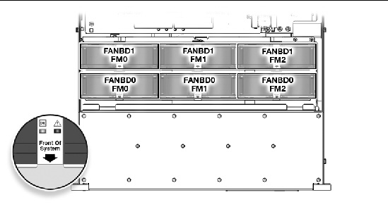
FIGURE 3-6 shows the fan module locations.
FIGURE 3-6 Fan Module Locations
The following LEDs are lit when a fan module fault is detected:
If an overtemperature condition occurs, the front panel CPU overtemperature LED becomes lit and a message is displayed on the console and logged by the ILOM. Refer to the Sun Integrated Lights Out Manager User's Guide.
The system Overtemp LED might be lit if a fan fault causes an increase in system operating temperature. See Chapter 1, Sun Fire X4440 Front Panel Features for more information about system status LEDs.
FIGURE 3-7 Detecting a Faulty Fan Module

|
|
Caution - Hazardous moving parts. Unless the power to the server is completely shut down, the only service permitted in the fan compartment is the replacement of the fan modules by trained personnel. |
1. Extend the server into the maintenance position.
See Extending the Server to the Maintenance Position.
2. Unlatch the fan module door.
Pull the release tabs back to release the door. Open the top cover toward the rear of the server.
3. Identify the faulty fan module with a corresponding Service Required LED.
The Fan Fault LEDs are located on the fan board.
4. Using thumb and forefinger in between the two fans, pull the fan module up and out of the connector.
FIGURE 3-8 Removing a Fan Module

1. With the top cover door open, install the replacement fan module into the server (FIGURE 3-9).
The fan modules are keyed to ensure that they are installed in the correct orientation.
FIGURE 3-9 Installing a Fan Module

2. Apply firm pressure to fully seat the fan module.
3. Verify that the Fan OK LED is lit, and that the Fan Fault LED on the replaced fan module is not lit.
5. Verify that the Top Fan LED, Service Required LEDs, and the Locator LED/Locator button are not lit.
See Sun Fire X4440 Server Chassis Overview for more information about identifying and interpreting system LEDs.
Some versions of the Sun Fire X4440 Servers are equipped with redundant hot-swappable power supplies. Redundant power supplies enable you to remove and replace a power supply without shutting the server down, provided that the other power supply is online and working.

|
|
Caution - If a power supply fails and you do not have a replacement available, leave the failed power supply installed to ensure proper air flow in the server. |
The following topics are covered:
| Note - CRU: This customer-replaceable unit can be replaced by anyone. |
The following LEDs are lit when a power supply fault is detected:
See Power Supply LED Reference for power supply LED information.
See Sun Fire X4440 Front Panel Features and Sun Fire X4440 Rear Panel Features for more information about identifying and interpreting system LEDs.
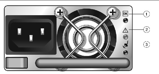
Each power supply contains a series of LEDs on the rear panel of the system.
FIGURE 3-11 Power Supply Status LEDs
If space is limited behind the server, you might need to remove the server from the rack. See Removing a Server From the Rack.

|
Caution - Hazardous voltages are present. To reduce the risk of electric shock and danger to personal health, follow the instructions. |
1. Determine which power supply (0 or 1) requires replacement.
A lit (amber) failure LED on a power supply indicates that a failure was detected.
2. Gain access to the rear of the server where the faulty power supply is located.
3. Release the cable management arm (CMA). (FIGURE 3-12)
The CMA is located at the rear of the server rack.
b. Rotate the cable management arm out of the way so that you can access the power supply.
FIGURE 3-12 Releasing the Cable Management Arm

4. Disconnect the power cord from the faulty power supply.
5. Grasp the power supply handle and press the release latch. (FIGURE 3-13)
6. Pull the power supply out of the chassis.
FIGURE 3-13 Power Supply Release Handle
.")
1. Align the replacement power supply with the empty power supply chassis bay.
2. Slide the power supply into the bay until it is fully seated. (FIGURE 3-14)
3. Reconnect the power cord (or cords) to the power supply (or supplies).
Verify that the AC Present LED is lit.
4. Close the CMA, inserting the end of the CMA into the rear left rail bracket (FIGURE 3-12).
FIGURE 3-14 Installing a Power Supply
.")
5. Verify that the following LEDs are not lit:
| Note - See Sun Fire X4440 Front Panel Features and Sun Fire X4440 Rear Panel Features for more information about identifying and interpreting system LEDs. |
6. Verify the status of the power supplies.
Solaris OS: At the -> prompt, type the showenvironment command.
Linux OS: Refer to the Sun Integrated Lights Out Manager User's Guide.
Windows OS: Refer to the Sun Integrated Lights Out Manager User's Guide.
The DVD drive and front USB board are mounted in a removable module that is accessible from the front panel of the system. The DVD/USB module must be removed from the drive cage to service the drives backplane.
| Note - CRU: This customer-replaceable unit can be replaced by anyone. |
1. Remove media from the drive.
2. Prepare the server for service.
b. Disconnect the power cord (or cords) from the power supply (or supplies).
c. Attach an antistatic wrist strap.
See Performing Electrostatic Discharge and Antistatic Prevention Measures.
3. Remove the Sun Fire X4440 HDD7 hard drive.
See Sun Fire X4440 Server Chassis Overview for drive locations.
4. Release the DVD/USB module from the drives backplane. (FIGURE 3-15)
Use the sliding pull tab in the drive bay below the DVD/USB module to detach the module from the backplane.
5. Slide the DVD/USB module out of the drive cage.
6. Place the module on an antistatic mat.
FIGURE 3-15 Removing the DVD/USB Module
.")
1. Slide the DVD/USB module into the front of the chassis until it seats. (FIGURE 3-16)
2. Install the drive you removed during the DVD/USB module removal procedure.
FIGURE 3-16 Installing the DVD/USB Module
.")
| Sun Fire X4440 Server Service Manual | 820-3836-14 |
Copyright © 2010, Oracle and/or its affiliates. All rights reserved.