| Sun Ultra 24 Workstation Service Manual |
| C H A P T E R 2 |
|
Unpacking, Cabling, and Powering the Sun Ultra 24 Workstation |
This chapter describes how to connect cables and power the Sun Ultra 24 workstation on and off. The chapter includes the following sections.
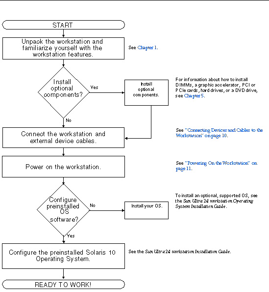
Use the following flowchart to assist you with installing the Sun Ultra 24 workstation.
EXAMPLE 2-1 Process Flow for Setting Up the Sun Ultra 24 Workstation
Carefully unpack all workstation components from the packing cartons. The following items are contained in the package.
|
Documentation[1] |
A country kit is optional, ships in a separate package and includes a power cable, keyboard, and mouse.
|
1. Connect the workstation power cord to a grounded electrical outlet (see FIGURE 2-1).
FIGURE 2-1 External Cable Connections

2. Connect the keyboard to a USB connector on the back or front panel (see FIGURE 2-1).
3. Connect the mouse to the USB connector on the underside of the keyboard or to a USB connector on the front or back panel (see FIGURE 2-1).
4. Connect the Ethernet cable to the Ethernet connector on the Sun Ultra 24 workstation and connect the other end of the cable to an Ethernet RJ-45 jack (see FIGURE 2-1).
5. Connect the monitor cable to the external port of the PCIe graphics card that is installed in the PCIe-2 slot (fourth slot from the bottom); see FIGURE 2-2.
Your graphics card might require a DVI cable to connect to your monitor.
FIGURE 2-2 Connecting the Monitor to the System Image

6. Connect any additional external devices to the workstation’s other connectors.
|
1. Turn on the power to the monitor and to all external devices.
2. Turn the power switch on the rear of the workstation to the On ( | ) position.
3. Press and release the power switch on the front panel.
4. After several seconds, verify that the Platform Power LED next to the power switch is lit.
The Platform Power LED lights after the workstation begins the internal booting process.
5. If you need to change the system parameters in the BIOS, press the F2 key during the POST process to access the BIOS Setup Utility.

|
Caution - Be careful when making changes to the system BIOS, as some changes can cause your system to malfunction. |
|
1. Save your data and close any open applications.
2. Read the following power-off options and then follow one of the options to turn off the workstation.
In most cases, this initiates an orderly shutdown of the operating system and shuts off the workstation power.
|
|
Caution - To avoid data loss, use the first option whenever possible. |
This option shuts down the power to the workstation but does not initiate an orderly shutdown of the operating system. This option might result in data loss.
| Note - After powering off the workstation, wait at least four seconds before powering on the workstation again. |
| Sun Ultra 24 Workstation Service Manual | 820-2480-12 |
Copyright © 2009 Sun Microsystems, Inc. All rights reserved.
 To Connect Devices and Cables