Sun Ultra 24 Workstation Hardware Features
|
This chapter provides an overview of the Sun Ultra 24 workstation hardware features and includes the following sections:
Front Panel
FIGURE 1-1 Front Panel Components

Figure Legend
|
1
|
Power Button
|
4
|
Two USB 2.0 ports
|
|
2
|
Power LED
|
5
|
Microphone-in jack
|
|
3
|
Two 1394 ports
|
6
|
Microphote-out jack
|
Back Panel
FIGURE 1-2 Back Panel Components

Figure Legend
|
1
|
Power Connector
|
10
|
Ethernet port
|
|
2
|
Power switch
|
11
|
Blank, unsed
|
|
3
|
Audio connector
|
12
|
x16 PCIe slot
|
|
4
|
Audio connector
|
13
|
x1 PCIe slot
|
|
5
|
Audio connector
|
14
|
x16 PCIe slot
|
|
6
|
Audio connector
|
15
|
PCI slot
|
|
7
|
Audio connector
|
16
|
PCI slot
|
|
8
|
Audio connector
|
17
|
PCIe x8 (4,1) slot
|
|
9
|
Four USB Ports
|
18
|
Release screws (captive) for
left side access cover
|
Internal Components and ConnectorsInternal Components
FIGURE 1-3 Internal System Components

Figure Legend
|
1
|
Power supply
|
8
|
x16 PCIe slot
|
|
2
|
Memory (DIMMs)
|
9
|
Two PCI slots
|
|
3
|
System fan
|
10
|
PCIe x8 (4,1) slot
|
|
4
|
Heatsink and CPU
|
11
|
DVD release lever
|
|
5
|
Blank unused slot
|
12
|
I/O board release screw (captive)
|
|
6
|
x16 PCIe slot
|
13
|
Hard drive cage
|
|
7
|
x1 PCIe slot
|
14
|
Hard drives
|
Power Supply Cables and Connections.
FIGURE 1-4 Power Supply and Component Cable Connections to Motherboard

Figure Legend
|
1
|
Power supply to DVD drive
|
|
2
|
Storage Backplane
|
|
3
|
Power supply P1 to motherboard PWR1
|
|
4
|
Power supply P2 to motherboard PWR2
|
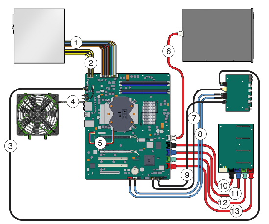
Component Cables and Connections
FIGURE 1-5 Internal Component Cables and Connections
 [ D ]
[ D ]
Figure Legend
|
1
|
Power supply P1 to MB PWR1
|
8
|
I/O Board J8 to MB 13940-0 and 1394-1
|
|
2
|
Power supply P2 to MB PWR2
|
9
|
I/O Board J12 to MB FPB_CONN
|
|
3
|
I/O Board J1 to MB FPB_Audio
|
10
|
SATA 1 to Storage Backplane HDD1 (black)
|
|
4
|
System Fan to MB SYS_FAN
|
11
|
SATA 2 to Storage Backplane HDD2 (blue)
|
|
5
|
CPU Fan to MB CPU_FAN
|
12
|
SATA 3 to Storage Backplane HDD3 (green)
|
|
6
|
DVD to MB SATA 0 (white)
|
13
|
SATA 4 Storage Backplane HDD4 (red)
|
|
7
|
I/O Board J5 to MB FPB_USB
|
|
|
| Sun Ultra 24 Workstation Service Manual
|
820-2480-12
|
   
|
Copyright © 2009 Sun Microsystems, Inc. All rights reserved.