| C H A P T E R 5 |
|
Replacing the Motherboard and Associated Components |
This chapter describes the removal and installation procedures for the motherboard and associated components. The procedures described in this chapter are written for workstation service providers and system administrators.
| Note - Only Sun authorized service providers should perform the procedures described in Section 5.5, Replacing the Motherboard Tray Assembly. |
This chapter contains the following sections:

|
Caution - To prevent equipment damage, review the safety requirements, safety symbols, and safety precautions in Section 4.1, Safety Informationbefore you perform any replacement procedure. Additional cautions, warnings, and instructions are provided in the Ultra 40 Workstation Safety and Compliance Guide, part number 820-0122. The document is available at: http://www.sun.com/documentation/ |

|
Caution - The procedures in this chapter should be performed with the workstation chassis on its side. |
FIGURE 5-1 shows the devices and cables on the Ultra 40 motherboard.
FIGURE 5-2 shows the devices and cables on the Ultra 40 M2 motherboard.
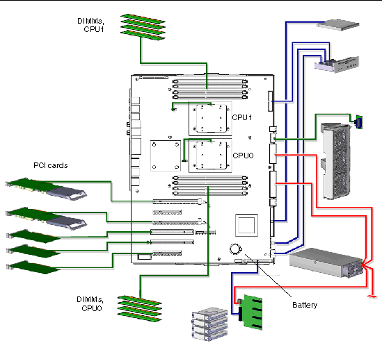
FIGURE 5-1 Ultra 40 Motherboard Components
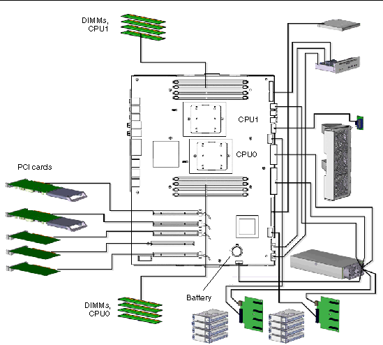
FIGURE 5-2 Ultra 40 M2 Motherboard Components

|
Caution - DIMMs are installed in adjacent pairs. However, if you replace a single DIMM, the new DIMM must be identical to the DIMM that you removed. |
Sun Ultra 40 memory is installed as pairs of DDR400 PC3200 Registered ECC DIMMs. Sun Ultra 40 M2 memory is installed as pairs of DDR2-667 DIMMs.
The DIMMs in a pair must be identical, from the same manufacturer with the same type and number of memory devices, the same amount of memory per device, and the same memory speed. All installed DIMMs must have the same memory speed.

|
Caution - The Ultra 40 and Ultra 40 M2 DIMMs are numbered the same but located differently, and this difference is critical. On the Ultra 40, DIMM slots 0/1 and 4/5 are closestto their respective CPUs. On the Ultra 40 M2, DIMM slots 0/1 and 4/5 are farthestfrom their respective CPUs. See FIGURE 5-4and FIGURE 5-5respectively. The slot color coding and provisioning rules are the same. |
The DIMM connectors on the motherboard are color-coded blue and black:
TABLE 5-1 lists some common DIMM pair configurations.
When your workstation boots, the BIOS checks for compatible memory modules. See Section 5.2.4, BIOS Memory Check for additional information.
Before replacing DIMMs, verify that the latest version of BIOS, system firmware, and recommended system patches are installed on your system. If necessary, check the Sun System Handbook at SunSolve Online:
http://sunsolve.sun.com/handbook_pub/
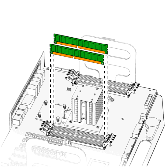
FIGURE 5-3 Minimum DIMM Configuration (Ultra 40 shown)
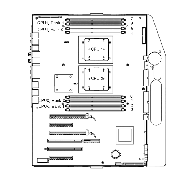
FIGURE 5-4 Ultra 40 DIMM Configurations for Single and Dual CPU
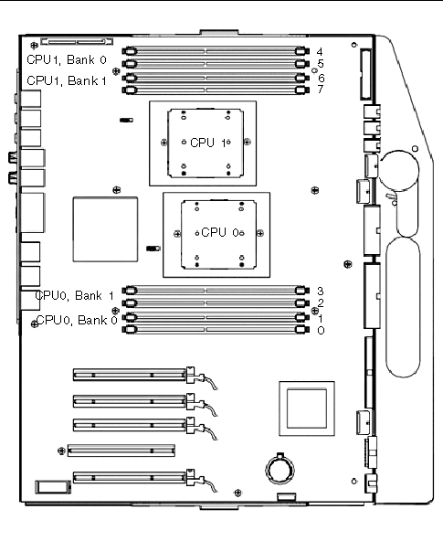
FIGURE 5-5 Ultra 40 M2 DIMM Configurations for Single and Dual CPU
1. Power off the system, open and position the chassis, and remove the access panel.
Refer to Section 4.3, Preparing the Workstation for Servicing.
2. Open the memory cooler (Ultra 40 M2 Only).
a. Squeeze the latch until it releases.
b. Raise the housing to expose the DIMMs.
See FIGURE 5-6.
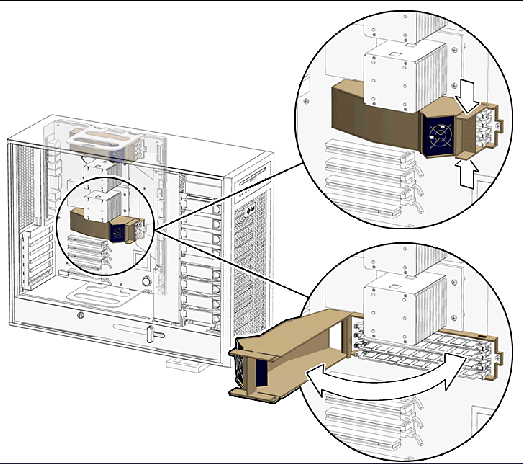
FIGURE 5-6 Memory Cooler (Ultra 40 M2 Only)
3. Release the DIMM by simultaneously pressing down on both ejector levers at the ends of the DIMM slot.
See FIGURE 5-7.
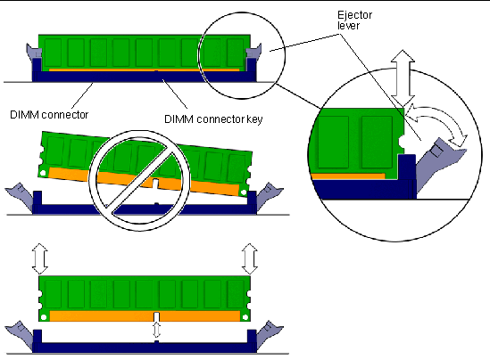
4. Lift the DIMM straight out of the DIMM slot.
See FIGURE 5-7.

|
Caution - Do not lift the DIMM out of the DIMM slot at an angle. This can damage the edge connector for the DIMM or the DIMM slot. |
5. Set the DIMM aside on an antistatic mat.
6. Repeat Step 3 through Step 5 until you have removed all relevant DIMMs.
Before installing new DIMMs, ensure they meet the following requirements:

|
Caution - The Ultra 40 and Ultra 40 M2 DIMMs are numbered the same but located differently, and this difference is critical. On the Ultra 40, DIMM slots 0/1 and 4/5 are closestto their respective CPUs. On the Ultra 40 M2, DIMM slots 0/1 and 4/5 are farthestfrom their respective CPUs. See FIGURE 5-4and FIGURE 5-5respectively. The slot color coding and provisioning rules are the same. |
Before installing memory, verify that the latest version of BIOS, system firmware, and recommended system patches are installed on your system. If necessary, check the Sun System Handbook at SunSolve Online:
http://sunsolve.sun.com/handbook_pub/

1. Power off the system, open and position the chassis, and remove the access panel.
Refer to Section 4.3, Preparing the Workstation for Servicing.
2. Remove the new DIMM from its antistatic container.
3. Review the recommended DIMM installation and configurations before installing the DIMM.
See FIGURE 5-4 (for Ultra 40) and FIGURE 5-5 (for Ultra 40 M2), and refer to Section 5.2, Replacing the DIMMs.

|
Caution - If you replace a single DIMM, the replaced DIMM must be identical to the one that you removed. |
4. Align the DIMM notch to the DIMM connector key.
See FIGURE 5-8.
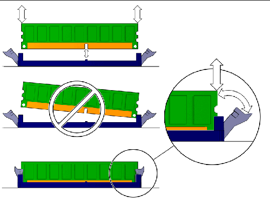
FIGURE 5-8 Aligning and Securing the DIMM to the DIMM Connector Slot
5. Using both thumbs, press the DIMM straight down into the DIMM connector slot until both ejector levers close, locking the DIMM in the DIMM connector slot.
See FIGURE 5-8.
| Note - The DIMMs must be inserted evenly, straight down into the DIMM connector slot, until the ejector levers lock into place. |
The DIMM is seated when you hear a click and the ejector levers are in the vertical position.
6. Repeat Step 4 through Step 5 until all DIMMs are installed.
7. Verify that the DIMM ejector levers are upright, seated, and tight.
8. Close the memory cooler as shown in FIGURE 5-6 (Ultra 40 M2 only).
9. Install the side cover and the access panel, power on the system, and verify the installation.
Refer to Section 8.1, Reassembling the Workstation.
| Note - Before installing DIMMs, verify that the latest version of BIOS, system firmware, and recommended system patches are installed on your system. |
During system startup, BIOS checks for DIMM type and DIMM manufacturer, and signals what it finds. TABLE 5-2 shows the result and the action taken by the BIOS.
| Note - If you have only one DIMM pair installed and the DIMMs have a different architecture, the system beeps three times and powers off. No message is displayed. |
Each CPU has four memory slots and two banks. The two black slots comprise physical Bank 0 and the two blue slots comprise physical Bank 1. See FIGURE 5-4 (for Ultra 40) and FIGURE 5-5 (for Ultra 40 M2).
BIOS references memory by bank if a problem is found. For example, if each DIMM of a DIMM pair is from a different manufacturer the following error is displayed:
This message means that each of the two DIMMs in the Bank 0 slots comes from a different manufacturer. The system still attempts to use the DIMMs, but this configuration is not supported.
This message means that each of the two DIMMs in the blue slots has a different internal memory layout. The system does not use the DIMMs.
A system must have at least one functional pair of DIMMs to display a message. A system with more than one pair of DIMMs might display more than one message.
This section describes removal and installation of the battery.
The battery is a CR 2032, part number is F371-2210-01.
1. Power off the system, open and position the chassis, and remove the access panel.
Refer to Section 4.3, Preparing the Workstation for Servicing.
2. Release the battery by pressing the battery clip away from the battery until the battery shifts out of the battery socket.
See FIGURE 5-9 for Ultra 40 and FIGURE 5-10 for Ultra 40 M2.
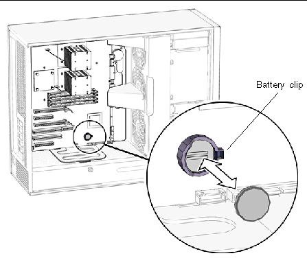
FIGURE 5-9 Removing the Battery From the Motherboard, Ultra 40
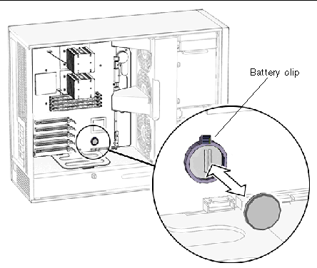
FIGURE 5-10 Removing the Battery From the Motherboard, Ultra 40 M2
TABLE 5-3 lists the battery specifications.
| Note - The workstation does not function without the battery. |
The battery fits directly into a socket on the motherboard. There are no additional fasteners or cables.
1. Identify the battery installation site, as shown in FIGURE 5-9.
2. Position the battery over the battery socket with the plus (+) side up.
3. Press the battery down into the socket until the battery clicks into place.
4. Install the side cover and the access panel, power on the system, and verify the installation.
Refer to Section 8.1, Reassembling the Workstation.
This section describes the removal and installation of PCI cards in the workstation.
The Ultra 40 motherboard supports six PCI connectors, as listed in TABLE 5-4.
|
PCI-0[1] |
||
The Ultra 40 M2 motherboard supports five PCI connectors, as listed in TABLE 5-4.
|
PCI-0[2] |
||
The card in PCI-E1 is designated the default console display and assigned the aliases screen and /dev/fb.You can move it to PCI-E3, but you must reconfigure the BIOS.
Each x16 slot without supplemental power can supply 75W.
When used with supplemental power, PCI-E1 and PCI-E3 each support a maximum power draw of 150W. This is sufficient for the NVIDIA Quadro FX 4500/5500 or the Quadro FX 3450/3500 3-D PCI E graphics cards supported for that configuration.
FIGURE 5-11 shows the location of PCI cards on the Ultra 40. FIGURE 5-12 shows the location of PCI cards on the Ultra 40 M2.
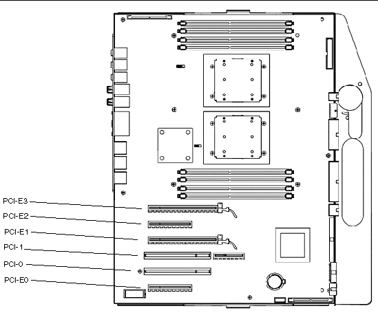
FIGURE 5-11 Ultra 40 PCI Card Location and Identification
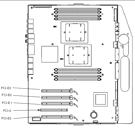
FIGURE 5-12 Ultra 40 M2 PCI Card Location and Identification
The PCI configuration includes two supplementary power cables used for either the NVIDIA Quadro FX4500/5500 or the Quadro FX3450/3500 graphics cards. The connectors appear in FIGURE 5-18 and FIGURE 5-19.
The NVIDIA Quadro FX 4500/5500 is a double width card. It is not possible to install more than two in a system (either Ultra 40 or Ultra 40 M2). The Ultra 40 M2 can support up to 4 FX3500, FX1500, FX560 or NVS 285 graphics cards.
This section describes how to enable SLI.
TABLE 5-6 lists the PCI cards and configurations.
To enable SLI, you need two of same cards installed. The following graphics cards are supported for SLI operation:
If these cards are already installed in your workstation, the SLI connector will be already installed. If you still need to install one or both cards, follow the instructions in Section 5.4.6, Installing a PCI Card.
1. Right-click on the desktop or click on the NVIDIA setting icon located on the taskbar and select nvidia display -> (select your monitor).
2. Select SLI-Multi GPU and select the enable SLI multi-GPU checkbox.
A message will appear stating that SLI is enabled and that a reboot is required.
To enable SLI for Linux operating systems:
1. Log in to the workstation as root (superuser).
This will modify the X configuration file automatically
4. Refer to the readme for more information on configuring the different operation modes. The readme files are located at:
/usr/share/doc/NVIDIA_GLX-1.0/readme.txt or
1. Power off the system, open and position the chassis, and remove the access panel.
Refer to Section 4.3, Preparing the Workstation for Servicing.
2. If there is an auxiliary PCI card power cable, disconnect it from the PCI card.
3. Using a No. 2 Phillips screwdriver, remove the screw that secures the PCI card retainer to the chassis rear panel.
See FIGURE 5-13. Place the screw aside in a container.

|
Caution - If you are removing a graphics accelerator from a PCI Express connector, ensure that you release the PCI-X connector latch. See FIGURE 5-14. |
4. Gently rock the PCI card forward, then lift it straight out of the PCI card slot, and place it aside on an antistatic mat.
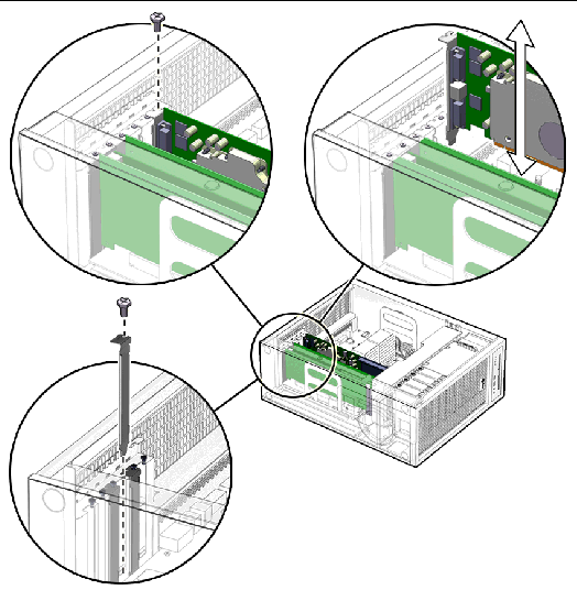
FIGURE 5-13 Removing the PCI Card Screws (Ultra 40 Shown)
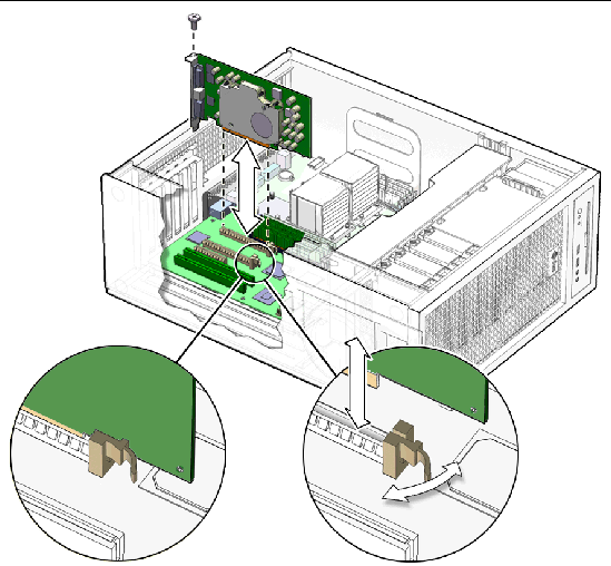
FIGURE 5-14 Releasing the PCI Card Latches and Removing a PCI Card (Ultra 40 Shown)
5. If you are not installing another PCI card in the empty slot:
a. Insert a filler panel into the rear panel slot.
The rear panel slot must be closed with a filler panel to meet system EMI and airflow requirements. See FIGURE 5-15.
b. Install the side cover and the access panel, power on the system, and verify the installation.
Refer to Section 8.1, Reassembling the Workstation.
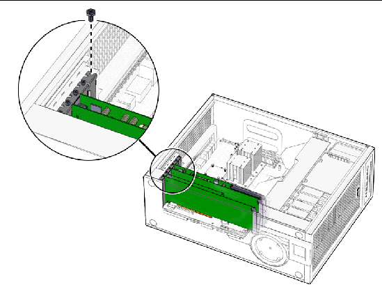
FIGURE 5-15 Installing a PCI Card Filler Panel (Ultra 40 Shown)
Before installing a PCI card, refer to Section 5.4.1, General PCI Guidelines and Section 5.4.3, Graphics Accelerators.
If the card is going to use SLI, see Section 5.4.4, Enabling SLI.
1. Power off the system, open and position the chassis, and remove the access panel.
Refer to Section 4.3, Preparing the Workstation for Servicing.
2. Locate the available PCI card slots.
If you are installing an additional PCI card, ensure that you install it in an appropriate slot. See Section 5.4.1, General PCI Guidelines.
3. Use the No. 2 Phillips screwdriver to remove the chassis filler panel from the PCI card slot that you wish to use.
Some PCI cards require use two slots. If necessary, remove a second chassis filler panel to accommodate these cards.
See FIGURE 5-16.
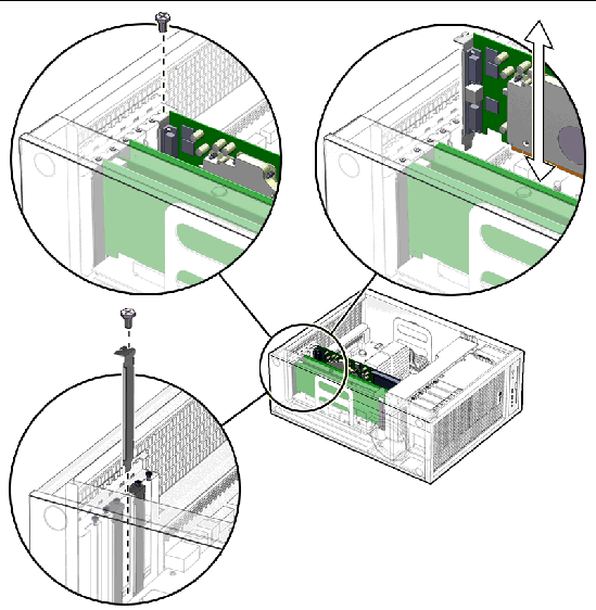
FIGURE 5-16 Opening the PCI Card Retainer(Ultra 40 Shown)
4. Remove the new PCI card from its antistatic container.
5. Position the PCI card so that the PCI bracket aligns with the chassis rear panel slot and the PCI card edge aligns with the motherboard PCI card slot.
6. Insert the PCI card into the PCI card slot.
If you are installing a long PCI Express card, be sure to engage the PCI E connector latch. See FIGURE 5-17.
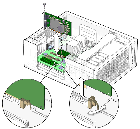
FIGURE 5-17 Installing the PCI Card (Ultra 40 Shown)
7. Firmly press the PCI card straight down into the PCI card slot until it is fully seated in the slot.
8. Use a No. 2 Phillips screwdriver to fasten the screw that secures the PCI card retainer.
See FIGURE 5-17.
9. For NVIDIA Quadro FX 4500, FX5500, FX3450 or FX3500 3-D PCI E Gfx cards in that require supplemental power, connect the supplemental power cables as follows:
10. Inspect the PCI card fasteners to verify the following:
11. If you are finished working, install the side cover and the access panel, power on the system, and verify the installation.
Refer to Section 8.1, Reassembling the Workstation.
| Tip - Boot the workstation with the -r option, so that the Solaris operating system can reconfigure itself for the new component. See Section 8.1, Reassembling the Workstation. |
This section describes the removal and installation of the motherboard tray assembly.

|
Caution - This procedure is intended for Sun authorized service providers only. |
The motherboard tray assembly is a single replaceable unit consisting of the motherboard and CPUs. See FIGURE 5-20.
CPUs are also available separately. See Section 5.3, Removing and Replacing the CPU and HeatsinkReplacing the Battery.
FIGURE 5-18 shows the connectors and slots on the motherboard.
| Note - Do not unscrew the motherboard from the tray assembly. |
To remove the motherboard tray assembly:
1. Power off the system, open and position the chassis, and remove the access panel.
Refer to Section 4.3, Preparing the Workstation for Servicing.
2. Disconnect all external cables from the back panel.
3. If necessary, remove the PCI cards.
Refer to Section 5.4.5, Removing a PCI Card
Place these components onto an antistatic mat.
4. Disconnect the following power and signal cables from the corresponding motherboard connectors and set them out of the way of the motherboard.
TABLE 5-7 lists the connectors. See FIGURE 5-18 for Ultra 40 and FIGURE 5-19 for Ultra 40 M2.
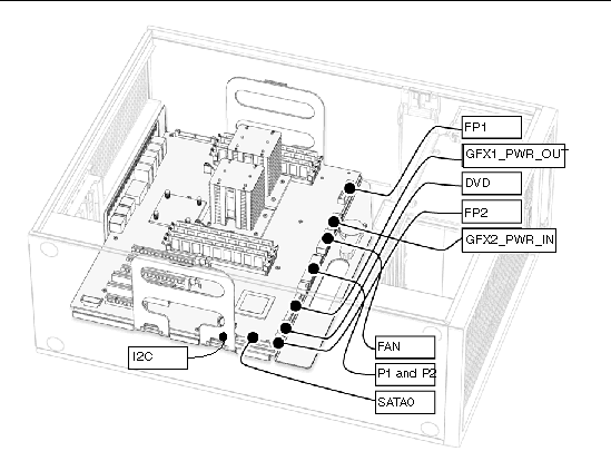
FIGURE 5-18 Motherboard Connectors for Ultra 40
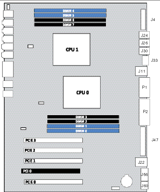
FIGURE 5-19 Motherboard Connectors for Ultra 40 M2
5. Turn the motherboard latch 90 degrees counterclockwise.
See FIGURE 5-20.
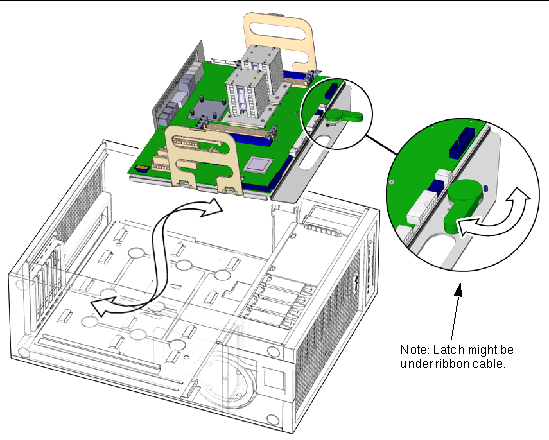
FIGURE 5-20 Motherboard, Tray, and Latch (Ultra 40 Shown)
6. Move the cables out of the way.
7. Using the handles on the tray assembly, tilt the motherboard to one side and lift it until it is free of the chassis.
See FIGURE 5-20.
8. Place the motherboard on an antistatic mat.
Proceed to Section 5.5.3, Installing the Motherboard Tray Assembly to install the new motherboard.
To install the motheboard tray assembly:
1. Remove the new motherboard tray assembly from its antistatic package and place it on an antistatic mat.
2. Move all cables out of the way.
3. Align the tray assembly’s rear panel connectors with the matching holes in the rear panel.
4. Gently lower the tray assembly while tilting it down.
See FIGURE 5-20.
5. Align the tray assembly so that the hooks fit into the holes of the tray.

|
Caution - Ensure that the hooks are located in the holes. Improper alignment might damage the motherboard. |
6. Turn the tray assembly latch 90 degrees clockwise to secure the motherboard.
Ensure that the motherboard connector panel aligns with the chassis rear panel.
7. Connect the cables to the corresponding motherboard connectors. See TABLE 5-7 and
Refer to Section 5.2, Replacing the DIMMs.
9. Inspect the motherboard to verify the following:

|
Caution - Take particular care to ensure that cables will not interfere with or get tangled in the fan tray. |
10. Install the side cover and the access panel, power on the system, and verify the installation.
Refer to Section 8.1, Reassembling the Workstation.
This section describes how to remove and replace the CPU and heatink/fan assembly on a Sun Ultra 40 Workstation.
| Note - The CPU should be replaced only by trained field service technicians. |
Each CPU is associated with a heatsink, which must be replaced with the CPU.
On single CPU systems, a bridge plug is plugged in to the CPU1 socket.
To remove a CPU from an Ultra 40:
1. Open and position the chassis.
Refer to Refer to Section 4.3, Preparing the Workstation for Servicing.
2. Unfasten the heatsink power cable from the motherboard connector labeled CPU0 Fan or CPU1 Fan. See FIGURE 5-21.

|
Caution - Heatsinks can get extremely hot. To avoid personal injury, allow sufficient time for them to cool before touching them. |
3. Loosen the four Phillips screws fastening the heatsink to the motherboard.
The screws are captive, and will not come away from the heatsink assembly.
4. Disconnect the heatsink power cable from the CPU0 Fan or CPU1 Fan connector on the motherboard.
5. Lift the heatsink gently up, exposing the CPU.
Place the heatsink upside down on a flat surface to prevent the thermal grease from contaminating other components.
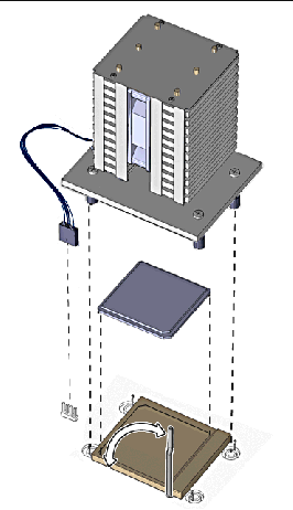
FIGURE 5-21 Removing and Replacing the CPU and Heatsink
6. Pull up the socket retaining lever holding the CPU in place.
7. Lift the CPU out of its socket.
Place it on an antistatic mat.
To replace a CPU in an Ultra 40:
1. Remove the new CPU from its antistatic wrapping.

|
Caution - Handle the CPU carefully, by its edges. Place it on an antistatic mat when you are not handling it. |
2. Ensure that the CPU socket retaining lever is in the upright position.
3. Align the CPU to its socket so that pin 1 of the CPU (indicated by the notched corner) is aligned with hole 1 of the socket (indicated by the arrow in the corner of the socket).
4. Insert new CPU in the socket, pushing it gently into place.
See FIGURE 5-21.
When it is properly aligned, the CPU slips easily into its slot. Do not force it or allow the pins to bend.
5. Press down on the socket retaining lever so it is in the fully closed position.
a. Clean any contamination from the top of surface of the CPU, using the supplied alcohol wipe.
The heatsink assembly already has thermal grease applied. You do not need to apply additional thermal grease.
b. Remove the plastic cover from the heatsink/fan assembly.
a. Remove the grease from the CPU and remove the thermal interface material from the heatsink using the alcohol wipe supplied with the motherboard.
b. Use the syringe that is supplied with the motherboard to apply approximately 0.5 ml of thermal grease to the center of the top of the CPU.
Empty the entire syringe onto the chip.
c. Using the wrapper of the alcohol wipe or a finger inserted into a clean plastic bag, spread out the thermal grease to a thin uniform thickness over the CPU.

|
Caution - Do not use an unprotected finger to spread the thermal grease, as the oils present will degrade the performance. |
7. Inspect the heatsink for dust and lint, and clean it if necessary.
8. Place the heatsink over the CPU, so that the captive screws align with the receptacles.
Ensure that the “Air Flow” symbol on top of the heatsink points toward the workstation back panel.
See FIGURE 5-21.
9. Tighten the Phillips screws until the heatsink is firmly in place.
10. Connect the heatsink power cable to the motherboard connector labeled CPU0 fan or CPU1 Fan.
11. Inspect the CPU and motherboard to ensure that all connectors are properly connected.
12. Verify that you have not left any tools, loose screws, or loose components inside the system.
13. Replace the fan tray if you removed it.
14. If you are finished working, install the side cover and the access panel, power on the system, and verify the installation.
Refer to Section 8.1, Reassembling the Workstation.
To remove a CPU from an Ultra 40 M2:
1. Open and position the chassis.
Refer to Refer to Section 4.3, Preparing the Workstation for Servicing.
2. Unfasten the heatsink power cable from the motherboard connector labeled CPU0 Fan or CPU1 Fan. See FIGURE 5-21.

|
Caution - Heatsinks can get extremely hot. To avoid personal injury, allow sufficient time for them to cool before touching them. |
3. Loosen the two Phillips screws fastening the heatsink to the motherboard.
The screws are captive, and will not come away from the heatsink assembly.
4. Disconnect the heatsink power cable from the CPU0 Fan or CPU1 Fan connector on the motherboard.
5. Lift the heatsink gently up, exposing the CPU.
Place the heatsink upside down on a flat surface to prevent the thermal grease from contaminating other components.
6. Pull the CPU socket lever slightly away from the socket. See FIGURE 5-22.
7. Pivot the lever up, into the fully open, vertical, position.
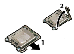
FIGURE 5-22 Releasing the Socket Lever
8. Open the hinged plate that covers the CPU until it is in the fully open position. See FIGURE 5-23.
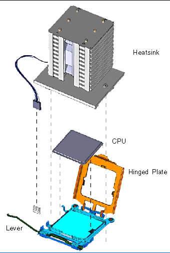
FIGURE 5-23 Removing and Replacing the CPU and Heatsink
9. Open the hinged plate that covers the CPU until it is in the fully open position. See FIGURE 5-24.
10. Lift the CPU out of the socket, leaving the lever in the vertical, open position. See FIGURE 5-24.
Place it on an antistatic mat.
To replace a CPU in an Ultra 40 M2:
1. Remove the new CPU from its antistatic wrapping.

|
Caution - Handle the CPU carefully, by its edges. Place it on an antistatic mat when you are not handling it. |
2. Ensure that the CPU socket retaining lever is in the upright position.
3. Align the CPU with the alignment keys, as shown in FIGURE 5-24.
| Note - Use the alignment keys in the CPU socket to match the alignment notches on the sides of the CPU. See FIGURE 5-24. |
When it is properly aligned, the CPU slips easily into its slot. Do not force it or allow the pins to bend.
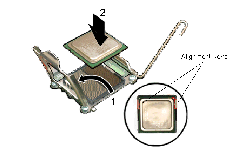
FIGURE 5-24 Opening the Retainer Plate and Installing the CPU
4. Press down on the socket retaining lever so it is in the fully closed position.
a. Clean any contamination from the top of surface of the CPU, using the supplied alcohol wipe.
The heatsink assembly already has thermal grease applied. You do not need to apply additional thermal grease.
b. Remove the plastic cover from the heatsink/fan assembly.
a. Remove the grease from the CPU and remove the thermal interface material from the heatsink using the alcohol wipe supplied with the motherboard.
b. Use the syringe that is supplied with the motherboard to apply approximately 0.5 ml of thermal grease to the center of the top of the CPU.
Empty the entire syringe onto the chip.
c. Using the wrapper of the alcohol wipe or a finger inserted into a clean plastic bag, spread out the thermal grease to a thin uniform thickness over the CPU.

|
Caution - Do not use an unprotected finger to spread the thermal grease, as the oils present will degrade the performance. |
6. Inspect the heatsink for dust and lint, and clean it if necessary.
7. Place the heatsink over the CPU, so that the captive screws align with the receptacles.
Ensure that the “Air Flow” symbol on top of the heatsink points toward the workstation back panel.
See FIGURE 5-21.
8. Tighten the Phillips screws until the heatsink is firmly in place.
9. Connect the heatsink power cable to the motherboard connector labeled CPU0 fan or CPU1 Fan.
10. Inspect the CPU and motherboard to ensure that all connectors are properly connected.
11. Verify that you have not left any tools, loose screws, or loose components inside the system.
12. Replace the fan tray if you removed it.
13. If you are finished working, install the side cover and the access panel, power on the system, and verify the installation.
Refer to Section 8.1, Reassembling the Workstation.
Copyright © 2008, Sun Microsystems, Inc. All Rights Reserved.