| C H A P T E R 3 |
|
Shelf Alarm Panel Description |
The shelf alarm panel (SAP) is a removable module mounted at the top right side of the shelf, above slots 9 through 14 in the shelf. It provides the connectors for the serial console interfaces of the shelf management cards, telco alarm connector, temperature sensors, Telco Alarm LEDs, user-definable LEDs, and Alarm Silence push button.
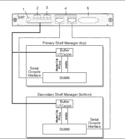
The I2C-bus devices on the shelf alarm panel are connected to the master-only I2C-bus of both shelf management cards. Only the active shelf management card has access to the shelf alarm panel.
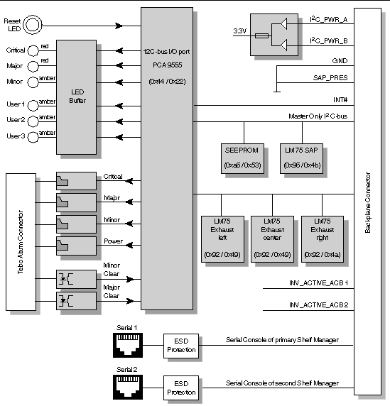
FIGURE 3-1 shows the connection between the shelf management cards and the shelf alarm panel. FIGURE 3-2 shows the block diagram for the shelf alarm panel.
This chapter includes the following topics:

FIGURE 3-1 Connection Between Shelf Management Cards and Shelf Alarm Panel

FIGURE 3-2 Shelf Alarm Panel Block Diagram
FIGURE 3-3 shows the components on the front panel of the shelf alarm panel.
FIGURE 3-3 Shelf Alarm Panel Front Panel Components
|
Serial console connector for primary (top) shelf management card |
|
|
Serial console connector for backup (lower) shelf management card |
|
The following sections give detailed descriptions of each of the shelf alarm panel components:
The Alarm Silence push button on the shelf alarm panel activates the alarm cutoff (ACO) state. When the alarm cutoff is activated, the active alarm LEDs blink and all of the alarm relays are deactivated.
| Note - This button only activates the alarm cutoff state. It does not clear alarms completely. |
The shelf alarm panel provides three Telco Alarm LEDs to indicate the presence of critical, major, and minor alarms. TABLE 3-3 describes the function of the Telco Alarm LEDs.
The User LEDs are user definable. They are connected to the I2C-bus I/O port on the PCA 9555 on the shelf alarm panel.
The shelf alarm panel provides the following RS-232 serial console interface connectors:
A full set of RS-232 signals, including modem control, is provided. The serial interface is implemented on the shelf management card.
Following is the default configuration for the serial console:
The serial console connectors are RJ-45 DTE serial ports. Refer to the Netra CT 900 Server Service Manual for the pinouts for these ports.
| Note - You must use shielded cables when connecting to either of the serial ports on the shelf alarm panel. |
The shelf alarm panel provides a telco alarm connector on the front panel. The telco alarm connection relay circuits are capable of carrying 60 VDC or 30 VAC at 1A. The shelf alarm panel accepts timed pulse inputs for clearing minor and major alarm states (there is no reset for the critical state). Reset is accomplished by asserting a voltage differential from 3.3V to 48V for between 200 and 300 milliseconds. The acceptance voltage range is from 0 to 48 VDC continuous (handles up to 60 VDC at a 50 percent duty cycle). The current drawn by a reset input does not exceed 12mA.
The telco alarm connector is a standard DB-15 connector. Refer to the Netra CT 900 Server Service Manual for the pinouts for this port.
The SEEPROM is connected to the master-only I2C-bus and is located at I2C address 0xa6/0x53. It is a Microchip 24LC256 device.
Three LM75 temperature sensors for measuring the exhaust temperatures and one sensor for the board temperature are located on the shelf alarm panel PCB. The temperature sensors are connected to the master-only I2C-bus.
Copyright © 2009 Sun Microsystems, Inc. All rights reserved.