| C H A P T E R 2 |
|
Shelf Description |
The Netra CT 900 server provides OEM equipment designers with carrier-grade, standards-based, high-availability solutions built on the PCI Industrial Computer Manufacturers Group (PICMG) specification. (Sun ATCA products are currently based on PICMG 3.0 R2.0 AdvancedTCA Base Specification ECN-001 and ECN-002, May 26, 2006.) This high-capacity platform features twelve node board slots and a redundant infrastructure (switch, management, power, and cooling), making it ideal for carrier-grade telecom and Internet applications. Beyond its high-availability features, the Netra CT 900 server is highly modular, scalable, and serviceable.
Hot-swappable system components provide built-in redundancy to simplify replacement and minimize service time. Redundant shelf management cards enable customers to manage multiple processor boards and conduct shelf diagnostics remotely for enhanced system reliability. Two 8U slots are reserved for PICMG 3.0/3.1 switches. The Netra CT 900 server routes Ethernet signals across the midplane without the use of cables, saving time in setup, maintenance, and repair, and eliminating the thermal challenges of traditional cabling methods.
This chapter includes the following topics:
This product complies with PICMG® 3.0 Revision 1.0. Following are the features of the Netra CT 900 server:
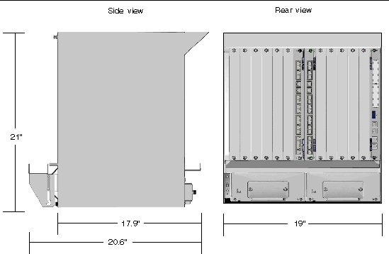
TABLE 2-1 and FIGURE 2-1 give the physical specifications for the Netra CT 900 server.
|
Depth, without front and rear cable management brackets (from PEM screw end to fan tray front edge) |
||

FIGURE 2-1 Physical Specifications, Netra CT 900 Server
The PICMG 3.0 Revision 2.0 specifications define the ATCA system architecture. The Netra CT 900 server sends all Ethernet signals across the midplane. By moving system traffic from the shared bus architecture to a fault-tolerant switched midplane, overall system throughput can be vastly increased while retaining the reliability and hot-swap capability of ATCA.
The Netra CT 900 server incorporates a 14-slot ATCA monolithic midplane with two dedicated shelf management card slots, one shelf alarm panel (SAP) slot, three fan tray slots, and two power entry module (PEM) slots.
The Netra CT 900 server also accommodates dual redundant switches and twelve node boards. Following are definitions of the switches and the node boards:
The physical slots are sequentially numbered from left to right. The logical slots are numbered from 1 through 14. Refer to TABLE 2-2 for the physical-to-logical slot mapping.
Logical slots 1 and 2 (physical slots 7 and 8) are the switch slots for the Dual Star Base interface. Base interface channel 1 of logical slot 1 and 2 is cross-connected to both shelf management card slots on the midplane.
The Fabric interface in the midplane is wired as a Dual Star, supporting four ports per channel.
Synchronization clocks are bused between all fourteen ATCA slots and are terminated at both ends.
The update channels are wired between adjacent midplane slots (see TABLE 2-2). The switches installed in physical slots 7 and 8 (logical slots 1 and 2) are interconnected with their update channel, which can be used to pass data or routing information between the switches. The update channel routing for the other slots is configured to support connections between single-slot ATCA boards.
The Intelligent Platform Management Bus (IPMB) interfaces are routed to the ATCA slots in a radial configuration. The IPMBs are wired redundantly. Every ATCA board is connected to an IPMB-A and IPMB-B interface, and they are routed to both dedicated shelf management card slots on the midplane.
The two slots to the right of physical slot 14 are designed to accept the two shelf management cards. The dedicated shelf management card slots are wired to both IPMB buses, Base interface channel 1 of the switch slots, and to the fan tray connectors on the midplane. The dedicated shelf management card slots also have interconnected signals that allow the shelf management cards to run in a redundant configuration. The shelf management cards also connect to the shelf alarm panel to provide shelf-level serial I/O, telco alarms, and telco relay outputs. They also connect to the power entry modules to allow for the monitoring and hot-swapping of the power entry modules. See Chapter 4 for more information on the shelf management cards.
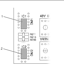
The midplane incorporates two 24LC256 SEEPROMs that are used by the dedicated shelf management cards to store shelf FRU data. Both SEEPROMs are at I2C address 0xa4, but they are on different inter-integrated circuit (I2C) buses. I2C bus Channel 1 of both shelf management cards is connected to SEEPROM1 (DM1) on the midplane, and I2C bus Channel 2 is connected to SEEPROM2 (DM2) on the midplane. Only the active shelf management card has access to the SEEPROMs on the midplane.

FIGURE 2-2 SEEPROM Location on the Midplane (Back View)
The Netra CT 900 server contains three front-pluggable fan trays. Each fan tray contains two fans for cooling the front boards and the rear transition module section of the shelf. Air is guided through cutouts in the midplane to provide cooling for the rear transition module section.
The fan speed is monitored by a tachometer signal sent from the fan trays to the shelf management card. The shelf management card regulates the fan speed with a DC voltage signal.
There are three modular fan trays at the front of the shelf. The display module at the front of each fan tray provides a blue Hot-Swap LED, a red Alarm LED, and a green Fan-Tray-Good LED, as well as a Hot-Swap push button. FIGURE 2-3 shows the location of these LEDs on the fan tray.
FIGURE 2-3 1Gbe Chassis Fan Tray LEDs
The temperature sensors (LM75) in the fan trays measure the intake temperature of the shelf. The temperature sensors are connected to Channel 3 of the master-only I2C-bus.
The SEEPROM (Microchip 24LC256) on the fan tray control board stores the FRU data and is connected to Channel 3 of the master-only I2C-bus.
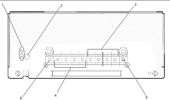
There are two hot-pluggable redundant power entry modules (PEMs) at the back of the shelf (FIGURE 2-4).

FIGURE 2-4 Power Entry Module Terminal Posts
Each power entry module provides four feeds with a capability of 28A each, of which 27.6 Amps is available per feed for use. There are two 28A fuses for each power feed at -48V and VRTN. Power filtering consists of filtered power terminals at the back panel of the power entry module, and a discrete line-filter is provided for each power input. The midplane is divided into four power segments. This topology is used to keep the maximum current per fuse lower than 28A.

|
Caution - Although there are fuses in the power entry circuit of the shelf, the power lines have to be protected on the rack level with 28A breakers. |
The input voltage range for the shelf is from -40.5 VDC to -72 VDC. The shelf is capable of distributing:
A signal from the shelf management card, which is grounded by a power entry module, indicates the presence of the power entry module in the shelf. A stud is provided at the back side of the shelf that is wired to the shelf ground.
Each of the four redundant power feeds supplies power to a separate zone of the midplane. FIGURE 2-5 illustrates how power is distributed within the Netra CT 900 server.
FIGURE 2-5 Power Distribution for Netra CT 900 Server (Rear View)
Node board power can be affected by CPU type, memory configuration, mezzanine cards (PMC or AMC), and ARTMs.
As the industry moves to multi-core CPUs, the number of cores can have an impact on power depending on the design. UltraSPARC T1 comes in four, six, and eight core. UltraSPARC T2 comes in six and eight core for ATCA blades. CPU workload represents a significant variable in power calculations. One of the significant advantages of the multi-core architecture is high memory utilization. In the past, single-core CPUs running memory stress programs would result in memory power data that was 30-50% higher than found with actual applications. This is not the case with UltraSPARC Core Multi Thread (CMT) architecture. Applications yield peak power data nearly the same as with memory stress tests. In UltraSPARC CMT designs, memory clocking is gated when accesses are idle. This results in a significant power delta between idle and full load.
Memory power is affected by configuration of a given DIMM. As memory technology matures, higher and higher density Integrated Circuits (ICs) become available. The higher the density, the fewer ICs are needed for a given size DIMM. The number of ICs used will determine the power. For example, 2GByte ECC DIMMs can be made with either 36 512Mbit DRAM ICs or 18 1Gbit DRAMs ICs. In this case, a 1GByte DIMM made with 512Mb will have a similar power demand as a 2GByte DIMM made with 1Gb ICs. Because node board power is limited, often the only way to accommodate a higher density DIMM configuration is when the memory technology progresses to the point where the power consumption is the same as the lower density.
Mezzanine cards are another variable in node board power, and most newer node board designs have moved to Advanced Mezzanine Card (AMC) designs. AMCs can support a wide variety of configurations from hard drives to Sonet interfaces. The challenge to power planners is that these cards are hot pluggable from the front and could be changed at some point. ARTMs are logically an AMC in a different form factor. In the case of the Sun CP32x0 ARTMs, they can house two SAS drives.
IPMC EKeying software verifies AMC and ARTM power and will not power on a node board if the sum of the components exceeds the maximum allowed. Power distribution planning is a primary end-user of power data, and, therefore we provide worse case numbers for a given configuration.
The ATCA specification requires the support of dual power feeds to all front boards (PICMG 3.0 section 4.1.1). Because of power density and typical central office wiring practices, the input power is divided into four power groups (zones). The word zone in this context might be a bit confusing because the midplane signals are grouped by connector and referred to as zones in the ATCA PICMG Specifications. Also, the term zone can refer to the grouping of node boards, fantrays, and ACBs.
Power to the node boards is distributed through Zone 1 connectors. All power zones are not equal, and zones 2 and 3 have three node boards, a switch, a fantray, and an ACB, as shown in FIGURE 2-5.
Central Office or Data Center power distribution provides DC power feeds that can vary from 15 to 50 AMPs per feed. The Netra CT 900 server has four 30A input feeds (derated to 28A for Safety) to the redundant Power Entry Modules (PEMs A and B). There is an additional loss through the PEMs, so the maximum current is 27.6A per feed.
The other variable is input voltage. ATCA PICMG 3.0 specifies a minimum input voltage to the shelf of -40.5VDC. The actual shutdown limit for the node boards shall be below -39.5VDC to provide for the drop across the midplane. For power planning, -40.5 VDC is used. Therefore, the worse case power-per-feed or zone is as follows:
This calculation is the maximum power available under worst-case conditions, which occurs at minimum input voltage.
As stated previously, the loading of each of the four power feeds is different. Calculating the zones with the most load results in the following.
This calculation leaves almost 50W of margin for Zone 2 and 3, which have the most load.
The switch can consume 200 Watts of power. For example, the Netra CP3240 switch has three AMC slots plus it supports an optical ARTM with up to six 10G SFP+ transceivers.
As you can see this result is under the total power feed capacity of 4,471 Watts.
For power distribution planning, it might not be practical to use different powers for different feeds. One approach would be to take the worst-case zone and multiply it by four.
Using the previous example: worst-case Zones 2 and 3 power is 1,089 x 4 = 4,356 Watts.
These numbers are worst-case numbers, and there are other node boards that either can be configured to less than 200watts or will be less, based on software applications running.
| Note - Keep in mind these calculations are for example purposes and actual load values can change when other memory and peripherals become available. |
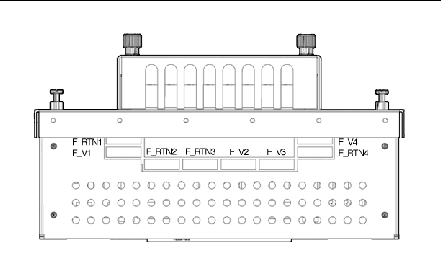
The four feeds of each power supply are protected by a 28A fuse in the -48V path and a 28A fuse in the VRTN path. The fuses are inside each power entry module and can be replaced after removing the power entry module from the shelf.
FIGURE 2-6 shows the location of the fuses in the power entry modules.

FIGURE 2-6 Fuses in the Power Entry Modules
Copyright © 2009 Sun Microsystems, Inc. All rights reserved.