| C H A P T E R 1 |
|
Introduction to the Netra CT 900 Server |
This chapter provides an overview of the Netra CT 900 server’s basic hardware components. The Netra CT 900 server is an Advanced Telecommunications Computing Architecture (AdvancedTCA® or ATCA) packet-switching, backplane-based, rack-mountable server.
| Note - Reliability, Availability and Serviceability (RAS) metrics for the Netra CT 900 server are available through the Sun Sales office under a Non-Disclosure Agreement. |
The Netra CT 900 server complies with the following specifications:
The hardware components for the Netra CT 900 server can be broken down into four sections:
Two versions of the Netra CT 900 server are available: a 1GbE and a 10GbE version. For systems configured with Netra CP3240 switches functioning as 10GbE switches, the 10GbE server is required.
FIGURE 1-1 shows the components in a Netra CT 900 server 1GbE version from the front, and FIGURE 1-2 shows the components in a Netra CT 900 server 1GbE version from the back. To use the next generation node boards and advanced rear transition modules in the 1GbE chassis, fan trays must be upgraded to provide adequate cooling. (Refer to the Netra CT 900 Server Upgrade Guide, 820-3255)
FIGURE 1-3 shows the components in a Netra CT 900 server 10GbE version from the front, and FIGURE 1-4 shows the components in a Netra CT 900 server 10GbE version from the back. This chassis is designed for the next generation of switches, node boards, and advanced rear transition modules.
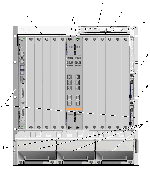
FIGURE 1-1 Netra CT 900 Server 1GbE Chassis Components (Front View)
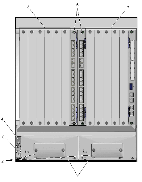
FIGURE 1-2 Netra CT 900 Server 1GbE Chassis Components (Back View)
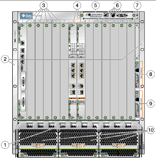
FIGURE 1-3 Netra CT 900 Server 10GbE Chassis Components (Front View)
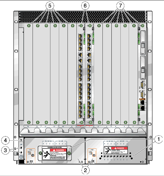
FIGURE 1-4 Netra CT 900 Server 10GbE Chassis Components (Back View)
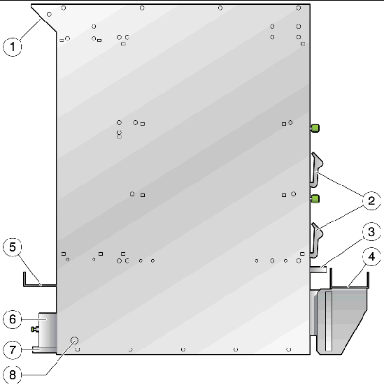
FIGURE 1-5 Netra CT 900 Server 10GbE Chassis Components (Left Side View)
|
Primary and secondary shelf manager ejectors (small handles right side of illustration) |
|
|
Filter tray hanle (below shelf manager handles above front cable management bracket |
|
|
Front adjustable cable management bracket (lower right side of illustration) |
|
|
Power entry module handle (lowest rectangle at bottom left of illustration) |
|
|
Chassis side mounting location (larger circle at the lower left) |
Copyright © 2009 Sun Microsystems, Inc. All rights reserved.