| Sun Netra CT 900 Server Installation Guide |
| C H A P T E R 4 |
|
Cabling the System |
This chapter provides pinouts for each port on the cards in the Sun Netra CT 900 server. Most of the software for each of the cards can be run through the serial port on each card, so if you are unsure where to begin, connect a cable to these serial ports on the following cards:
This chapter includes the following topics:
| Note - There are no cable connections to the shelf management cards. Each shelf management card has an Ethernet port that is not utilized by the user; instead, Ethernet traffic from the shelf management card is routed to the Ethernet ports on the switches. Serial and telco alarm traffic from the shelf management card are routed to the ports and LEDs on the shelf alarm panel. Refer to Connecting the Cables to the Shelf Alarm Panel and Connecting Cables to Switches for more information. |
The shelf alarm panel on the Sun Netra CT 900 server provides connectors for the serial console interfaces of the shelf management cards and the telco alarm.
FIGURE 4-1 Shelf Alarm Panel Front Panel Components
|
Serial console connector for primary (top) shelf management card |
|
|
Serial console connector for backup (lower) shelf management card |
|
To view the pinouts for each of the ports on the shelf alarm panel, see:
The serial console connectors to the primary and backup shelf management cards use standard RJ-45 connectors. The serial consoles are normally configured for 115200 baud, no parity, 8 data bits, and one stop bit.
| Note - You must use shielded cables when connecting to either of the serial ports on the shelf alarm panel. |
FIGURE 4-2 shows the RJ-45 serial connector pinouts and TABLE 4-1 gives the RJ-45 port signals.
FIGURE 4-2 RJ-45 Serial Connector Diagram

FIGURE 4-3 shows the connector pinouts for the RJ-45 and DB-9 connectors. Note that connectors are viewed with the cable going away from you.
FIGURE 4-3 Serial Console Cable Connector Pin Numbering
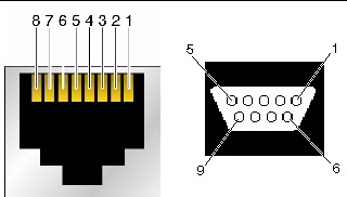
TABLE 4-2 gives the information necessary to create a console cable to convert the RJ-45 serial console connectors on the shelf alarm panel to DB-9 connectors, if necessary.
The telco alarm connector on the shelf alarm panel uses a standard Micro-DB-15 connector.
FIGURE 4-4 DB-15 Connector Diagram

TABLE 4-3 gives the pinouts for the telco alarm port.
The Sun Netra CT 900 server is available both as a front-access and a rear-access server. For rear-access servers, there are no active components on the rear transition module, so you must have the accompanying switch installed in the same slot at the front of the server, even though no cables will be connected to that front card.
FIGURE 4-5 shows the location of the ports on the switch, and FIGURE 4-6 shows the location of the ports on the rear transition module for the switch.
FIGURE 4-5 Ports and LEDs on the Switch
FIGURE 4-6 Ports on the Rear Transition Module for the Switch
|
Base and Fabric gigabit Ethernet 10/100BASE-TX management port |
|
To view the pinouts for each of the ports on the switch, see:
The Fabric gigabit Ethernet 10/100/1000BASE-T and Base 10/100/1000BASE-T Ethernet uplink ports on the switch use standard RJ-45 connectors.
The Base 10/100/1000BASE-T port is port number 17 on the Base network. The Base 10/100/1000BASE-T port is mutually exclusive with the second ShMC port. That is, if the ShMC cross-connection is being used, this port goes to the second ShMC and not the faceplate of the switch.
The Fabric gigabit Ethernet 10/100/1000BASE-T port is port number 16 on the Fabric network.
FIGURE 4-7 shows the pinouts for the 10/100/1000BASE-T ports.
FIGURE 4-7 10/100/1000BASE-T Ports Connector Diagram

TABLE 4-4 gives the signals for the 10/100/1000BASE-T ports.
The Base 10/100BASE-TX management port uses a standard RJ-45 connector. This port can be used to manage the Base and Fabric. This port and the 10/100 management port on the rear transition module can be used at the same time.
FIGURE 4-8 shows the pinouts for the 10/100BASE-TX management ports.
FIGURE 4-8 Base 10/100BASE-TX Management Port Connector Diagram

TABLE 4-5 gives the pinout information for the 10/100BASE-TX management port.
The Fabric gigabit Ethernet serial port and Base serial port on the switch use standard RJ-45 connectors. Note that the front serial port and rear transition module serial port are actually the same port. Only one of the interfaces can be used. Jumpers E7 and E8 can be used to steer the port out the front or out the back, or to allow software to control the direction.
FIGURE 4-9 shows the pinouts for the Fabric gigabit Ethernet serial port and Base serial port.
FIGURE 4-9 Fabric Gigabit Ethernet and Base Serial Ports Connector Diagram

TABLE 4-6 gives the pinout information for the Fabric gigabit Ethernet serial port and Base serial port.
TABLE 4-7 gives the minimum crossover cable pinouts needed to create a special cable or adapter to convert the serial ports’ RJ-45 connectors on the switch to the more standard DB-9 connectors.
For instructions on connecting cables to the Sun Netra CP3240 switch, refer to the switch product documentation. All of the documentation for the Sun Netra CP3240 switch is provided separately. Please refer to the following table for a list of the documentation for this product. The online documentation is available at:
http://docs.sun.com/app/docs/prod/cp3240.switch?l=en#hic
Refer to the documentation that came with your node board for cabling instructions for that board.
| Sun Netra CT 900 Server Installation Guide | 819-1175-14 |
Copyright © 2010, Oracle and/or its affiliates. All rights reserved.


