| C H A P T E R 3 |
|
Installing Additional Cards |
If you have any additional boards to install in the server, follow the instructions in this chapter. If you do not have any additional boards to install, go to Chapter 4.
This chapter includes the following topics:
Before you can install any additional cards into your system, you must first take the necessary antistatic precautions.
ESD ground jacks are located at the front and rear of the system. To protect system components from static shock when handling them, wear a wrist strap plugged into a ESD jack. Refer to FIGURE 2-2 and FIGURE 2-3 for the locations of the ESD ground jacks.
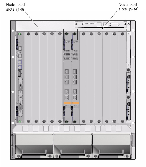
If you are installing additional cards in a rear-access model Sun Netra CT 900 server, you should first install the rear transition module at the rear of the server, and then install the front card in the front of the server. Even though you install the rear transition module first, it might be useful to look at the front of the server and locate the slot number where you will be installing the cards. Then go to the back of the server and install the rear transition module in that particular slot. Note that you can install additional cards only into node board slots 1-6 and 9-14; the other two slots are reserved for the switches. FIGURE 3-1 shows the location of the node slots from the front of the Sun Netra CT 900 server.
To install additional node cards into a front-access Sun Netra CT 900 server, go to Installing Node Cards. To install additional node cards into a rear-access Sun Netra CT 900 server, go first to Installing Rear Transition Modules, then go to Installing Node Cards.
FIGURE 3-1 Location of Node Slots

1. Verify that you have taken the necessary antistatic precautions.
See Antistatic Precautions for those instructions.
2. Go to the rear of the system and choose an appropriate slot for the rear transition module.
Rear transition modules must be installed inline behind the accompanying front board. For example, if the accompanying front board is going to be installed in slot 3, its rear transition module must be installed at the back of the system in slot 3.
3. Remove the slot filler panel from the selected node board slot, if necessary.
4. Get the rear transition module from the ship kit.
5. Perform any card-specific hardware procedures, if necessary.
Refer to the documentation that you received with the card for more information.
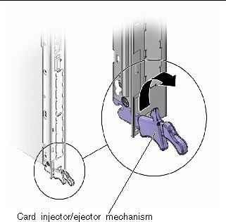
6. Prepare the card by opening the injector/ejector mechanisms at the top and bottom of the card (FIGURE 3-2).
FIGURE 3-2 Card Injector/Ejector Mechanism (Open Position)

7. Carefully align the edges of the card with the card guides in the appropriate slot.
It might be helpful to look into the enclosure to verify correct alignment of the rails in the guides.
8. Taking care to keep the board aligned in the guides, slide the card in until the injector/ejector mechanisms engage the retention bars.
9. Simultaneously push in the board and rotate the injector/ejector mechanisms inward to their closed positions to seat the midplane connectors.
10. Tighten the board retention screws to ensure the board is secured into the shelf.
11. Install the front node card into the shelf.
Go to Installing Node Cards for those instructions.
1. Go to the front of the system and locate the card slot where you installed the rear transition module at the rear of the system.
2. Remove the filler panel, if necessary.
The filler panel is secured to the card cage using two screws--one at the top of the filler panel, the other at the bottom. Store the filler panel in a safe place; you might need to use it again if you have to remove a card for an extended period of time.
3. Get the node card that you want to install in the Sun Netra CT 900 server from the ship kit.
4. Perform any card-specific hardware procedures, if necessary.
Refer to the documentation that you received with the card for more information.
5. Prepare the board by opening the injector/ejector mechanisms (FIGURE 3-2).
6. Carefully align the edges of the board with the card guides in the appropriate slot.
It might be helpful to look into the enclosure to verify correct alignment of the rails in the guides.
7. Taking care to keep the board aligned in the guides, slide the board in until the injector/ejector mechanisms engage the retention bars.
8. Simultaneously push in the board and rotate the injector/ejector mechanisms inward to their closed positions to seat the midplane connectors.
If system power is on, the node board Hot-Swap LED should light up. The Hot-Swap LED should blink for several seconds, and then go off. If the Hot-Swap LED does not go off after several seconds, push harder on the injector/ejector handles to verify that they are pushed in all the way.
9. Tighten the board retention screws to ensure the board is secured into the shelf.
Copyright © 2010, Oracle and/or its affiliates. All rights reserved.