| C H A P T E R 2 |
|
Hardware Installation and Service |
This chapter describes the Sun Netra CP3250 blade server hardware installation and service procedures.
This chapter contains the following sections:
Refer to the Important Safety Information for Sun Hardware Systems (816-7190) for general safety information and to the Netra CP3250 Blade Server Safety and Compliance Guide (820-5198) for specific safety information.
Read the following safety statements that are specific to the Sun Netra CP3250 blade server carefully before you install or remove any part of the system.
The installer must be familiar with commonly accepted procedures for integrating electronic systems and the general practice of Sun systems integration and administration. Although parts of these systems are designed for hot-swap operation, other components must not be subjected to such stresses. Work with power connected to a shelf only when necessary, and follow these installation procedures to avoid equipment damage.
This equipment is sensitive to damage from electrostatic discharge (ESD) from clothing and other materials. Use the following antistatic measures during an installation:
The other end of the antistatic wrist strap lead should be connected to one of the following:
The grounded mat or the chassis must be connected to a facility ground to prevent a floating ground.
The tools required for installation and service are as follows:
Refer to Section 1.6, System Components for information on hardware requirements.
Prepare for installation by reading and performing the following steps.
1. Become familiar with the contents of the documentation referenced in the steps.
2. Verify that all listed hardware and software are available (see Section 1.6, System Components).
3. Check power, thermal, environmental, and space requirements (see Section 2.2.1.1, Check Power, Thermal, Environmental, and Space Requirements).
4. Verify that local area network (LAN) preparations are completed (see Section 2.2.1.2, Local Network IP Addresses and Host Names Worksheet).
5. Ensure that the host names and their network IP addresses are allocated and registered at the site. Record this information in TABLE 2-1.
Observe that your environment meets the following requirements:
The Sun Netra CP3250 blade server fits into a standard ATCA shelf. If your installation requirements are different, contact your field applications engineer.
Collect the information listed in TABLE 2-1 to connect hosts to the LAN. Ask your network administrator for help, if necessary. This information is not needed for a stand-alone installation.
|
IP address[1] and host name for each Sun Netra CP3250 blade server client |
|
|
Type of name service and corresponding name server names and IP addresses--for example DNS and NIS (or NIS+) |
|
You might need the MAC (Ethernet) addresses of the local hosts to make name server database entries. You can see the MAC address in the console output while booting the blade server. You can also find it on the barcode label on the node blade server (see Section 1.7.1, Locating the Part Number and Serial Number Information).
This section summarizes the high-level procedures that are required to install the Sun Netra CP3250 blade server. Ensure that you are familiar with the information in Section 2.2.2, Configuring the Hardware through the end of Chapter 2 before installing the blade server.
The process to set up and configure a Sun Netra CP3250 blade server in a system includes the following procedures:
1. Configuring the blade server’s physical hardware.
For example, install the AMC and set switches, as necessary (Section 2.2.2, Configuring the Hardware).
2. Physically installing the advanced rear transition module (ARTM) as necessary (Section 2.2.3.1, Installing an Advanced Rear Transition Module (ARTM)).
3. Physically installing the Sun Netra CP3250 blade server, and any peripheral boards into the ATCA shelf Section 2.2.3, Installing the Netra CP3250 Blade Server in an ATCA Shelf).
4. Connecting the nodes to a local network. (Section 2.2.4, Connecting External I/O Cables).
5. Downloading and installing SunVTS (Section 4.1, Operating Systems), if you are running the Solaris Operating System on the Sun Netra CP3250 blade server and want to verify system integrity.
This section lists hardware installation and settings that might apply to your blade server configuration. Read and perform the procedures, as necessary, before installing the Sun Netra CP3250 blade server into the ATCA shelf.
 To verify if the fan tray upgrade is installed on a Netra CT 900 server, log into the Shelf Manager and issue the following command for fan trays 1,2, and 3:
If the “Product Part/Model Number” is 370-7764-xx, the fan trays must be replaced with high-speed fan trays. Refer to the Netra CT 900 Server Upgrade Guide (820-3255) for more information.
If the “Product Part/Model Number” is 371-3033-xx or newer, an upgraded fan tray is already installed.
Use the following table to locate your options and installation instructions.
If you are using one of the Netra advanced rear transition modules (ARTMs), refer to the documentation: Netra CP32x0 SAS Storage Advanced Rear Transition Module, Dual HD User’s Guide (820-3147) (ARTM-HD)
See Section B.3, Connectors and Pinouts for detailed connector pin assignments for the Sun Netra CP3250 blade server.
If you install the Sun Netra CP3250 blade server with an ARTM, the ARTM must be installed first.
| Note - Slots 1 through 6 and 9 through 14 are available for Sun Netra CP3250 blade servers. Slots 7 and 8 are reserved for the switch card. |
A compatible ARTM must be used with the Sun Netra CP3250 blade server for rear I/O access. The ARTM enables access to the network, a boot device, and a console terminal. You can use one of the Netra CP32x0 ARTMs or you can design your own ARTM-compatible transition module. For more information, see Section 1.4.2, Advanced Rear Transition Module.
1. Verify that you have taken the necessary antistatic precautions.
See Section 2.1.1, Equipment and Operator Safety.
2. From the rear of the system, choose the corresponding slot for the ARTM.
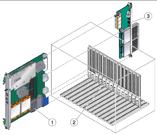
The rear transition module must be installed, inline, behind a compatible Netra blade server.
For example, if the Sun Netra CP3250 blade server will be installed in slot 3, the corresponding rear transition module must be installed at the back of the system in slot 3 (FIGURE 2-1). If you do not install the rear transition module and the Sun Netra CP3250 blade server in corresponding slots, the system will recognize the Sun Netra CP3250 blade server and not the rear transition module.
| Note - Slots 1 through 6 and 9 through 14 are available for Sun Netra CP3250 blade servers. Slots 7 and 8 are reserved for the switch card. |
FIGURE 2-1 Installing a Netra CP32x0 ARTM
|
Netra CP32x0 ARTM (installed from rear in corresponding slot to blade server’s front slot) |
3. Remove the slot filler panel from the selected slot, if necessary.
4. Retrieve the advanced rear transition module (ARTM) from the ship kit.
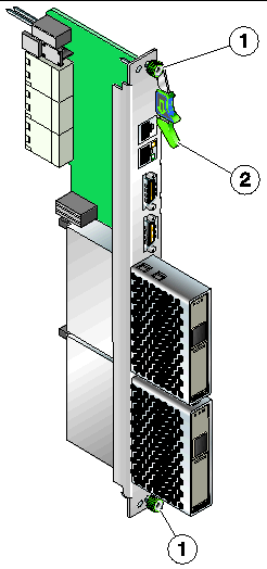
5. Prepare the rear transition module by opening the injector/ejector latch at the top of the module (FIGURE 2-2).
FIGURE 2-2 Injector/Ejector Latch and Locking Screw on the ARTM
6. Carefully align the edges of the ARTM with the card guides in the appropriate slot.
Look into the enclosure to verify correct alignment of the rails in the guides.
7. Keep the ARTM aligned in the guides, and slide the module in until the injector/ejector latches engage the card cage.
8. Push the ARTM into the backplane connectors, and close the latch.
9. Tighten the locking screws to ensure that the module is secured into the ATCA shelf.
10. Install the Sun Netra CP3250 blade server into the front of the ATCA shelf in the corresponding slot.
See Section 2.2.3.2, Installing the Blade Server Into the Shelf for instructions.
| Note - You can install the Sun Netra CP3250 blade server in any available slot in the ATCA shelf except for slots 7 and 8. |
1. If you have installed an advanced rear transition module (ARTM), go to the front of the system and locate the corresponding slot number of the ARTM.
2. Remove the filler panel from the blade server slot, if necessary.
The filler panel is secured to the card cage using two screws, one at the top of the filler panel, the other at the bottom. Store the filler panel in a safe place; you might need to use it again if you remove a blade server for an extended time.
3. Prepare the Sun Netra CP3250 blade server by opening the injector/ejector latches.
4. Carefully align the edges of the blade server with the guides in the appropriate slot.
Look into the enclosure to verify correct alignment of the rails in the guides.
5. Keep the blade server aligned in the guides and slide the blade server in until the injector/ejector latches engage the card cage.
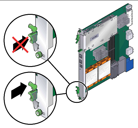
6. Push the blade server slightly into the backplane connectors and close the latches to seat the blade server in the connectors (FIGURE 2-3).
Push the upper latch lever to engage the blade server. When the upper and lower levers are engaged properly, the blue Hot-Swap LED blinks while the blade server is initializing. The blue LED turns off and the green OK LED lights when the blade server is ready for use.
| Note - If the hot-swap LED does not light, then wiggle and push the latch so it engages the hot-swap switch. |
FIGURE 2-3 Engaging the Netra CP3250 Blade Server Latch
7. Tighten the locking screws and the top and the bottom of the Sun Netra CP3250 blade server to ensure that it is secured to the ATCA shelf (FIGURE 2-2).
The blade server is now completely installed and will power on automatically.
8. Configure the switches accordingly as described in Section 4.4, Configuring Sun Netra CP3250 blade server For 1 GbE or 10 GbE Switches.
Front panel ports are typically used for maintenance and troubleshooting purposes in installed and running systems. External I/O cables are connected to the Sun Netra CP3250 blade server or to the Netra CP32x0 rear transition module when a rear transition module is used.
To connect each of these following cables:
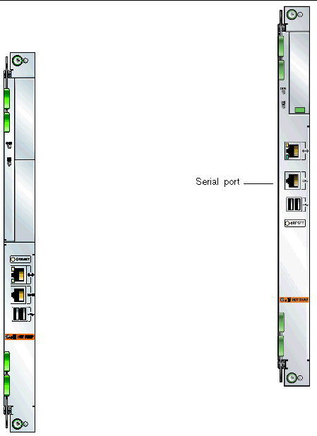
1. Connect a RJ-45 style serial cable to the serial console port on the front panel of the Sun Netra CP3250 blade server (FIGURE 2-4) or the Netra CP32x0 rear transition module.
Serial access (both front and rear) is through the same serial interface controller. If both ports are connected at the same time, console input and output can be performed through both, however, this configuration is not recommended. If both access interfaces are not connected at the same time, console input/output can be performed through NetConsole session via the ShMM.
2. Connect the other end of the serial cable to the serial port of the system serving as the serial console.
FIGURE 2-4 Serial Port on the Netra CP3250 Blade Server
3. Use one of the following to establish a full-duplex serial terminal connection with the Sun Netra CP3250 blade server:
For example, if you are using a UNIX system as the system console, at the UNIX prompt in a command tool or shell tool, or serial port A, type:
1. Connect a serial cable to the serial console port on the front panel of the Sun Netra CP3250 blade server (FIGURE 2-4) or the Netra CP32x0 rear transition module.
2. Connect the other end of the serial cable to the serial port of the system serving as the system console.
3. Set the serial communications settings to 9600 baud, 8 bit, 1 stop bit, no parity, and no handshake.
TABLE 2-2 provides a map of netinstall boot devices. You may need this information to understand which MAC address is associated with the system IP address on the install server.
For example, the Base Fabric interface is connected to the switch model-number in slot 8 of the ATCA shelf. To install to this device, select the xxx Ethernet interface from the BIOS setup menus.
The Sun Netra CP3250 blade server supports virtual LAN configuration for the Sun 10 GbE Multithreaded Networking Technolgy ports (MAC addresses 4, 5, 6, and 7). When configured, the virtual LAN feature enables the assignment of multiple MAC address to one port. TABLE 2-3 lists the extra MAC addresses available for the Sun 10 GbE Multithreaded Networking Technolgy ports.
You can remove the Sun Netra CP3250 blade server without powering off the entire chassis by performing these steps.
1. Power off the blade server.
See Section 2.3.2, Powering Off the Netra CP3250 Blade Server.
See Section 2.3.3, Removing the Netra CP3250 Blade Server.
1. Shut down the operating system.
Log in and shut down any OS operating on the blade server or its companion ARTM.
2. Deactivate the blade server.
Log in to the shelf manager and deactivate the blade server in the target slot.
For example, to shut down the blade server in slot 3, log in to the shelf manager and type:
Wait for the blue Hot-Swap LED to light steadily before removing the blade server.
1. Power off the Sun Netra CP3250 blade server.
Use the instructions in Section 2.3.2, Powering Off the Netra CP3250 Blade Server.
2. If installed, remove all cables from the front of the Sun Netra CP3250 blade server.
3. Loosen the locking screws to release the blade server from the ATCA shelf.
4. When the blue Hot-Swap LED lights steadily, release the upper latch and the lower latch at the same time to unseat the blade server from the connectors.
5. Remove the blade server from the ATCA shelf and place the blade server on an antistatic mat.
Sun Netra CP3250 blade servers are powered on automatically via the H8 BMC when you install the blade server into a slot in the ATCA shelf. Once installed, the blade server sequences through power-on states until it is fully powered on.
A power-off sequence is initiated either by a request from the shelf manager or a fault condition. The Sun Netra CP3250 blade server shuts down to standby power mode when the following upper critical threshold conditions are met:
Thermal trip of DC brick turns off all local power (standby included)
The Sun Netra CP3250 blade server supports a total of six DIMMs and the maximum memory capacity of 24 GB (using four 4 GB DIMMs). The Sun Netra CP3250 blade server accommodates the following DIMMs and configurations:
The Sun Netra CP3250 blade server supports DIMMs that have the following characteristics:
FIGURE 2-5 Locating DIMM Slots
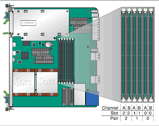
Populate DIMMs in matching pairs, starting with Pair 0, then adding Pair 1, then Pair 2.
There are two channels, Channel A and Channel B. DIMMs are identified as A0, B0, A1, B1, A2, and B2. Where Pair 0 would be A0 and B0, and so on.
The following procedure provides a general guide for installing additional memory. However, for specific directions on installing DIMMs on the Sun Netra CP3250 blade server, refer to the documentation that shipped with the DIMMs.
1. Access the blade server by performing one of the following procedures:
2. Take antistatic precautions: Attach and electrically ground the wrist strap.

|
Caution - Always wear a grounded antistatic wrist strap when handling DIMMs. |
3. Locate the DIMM connectors on the Sun Netra CP3250 blade server.
Select the connectors where you will install the DIMM. See FIGURE 2-5 for DIMM slot locations.
4. Remove the DIMM from its protective packaging, holding the module only by the edges.
| Note - Before installing a replacement DIMM, verify that the new DIMM is the same size as its paired DIMM. |
5. Holding the DIMM upright to the blade server, insert the bottom edge of the DIMM into the bottom of the slot’s hinge-style connector (FIGURE 2-6).
The socket and module are both keyed, which means that the DIMM can be installed only one way. With even pressure, push simultaneously on both upper corners of the DIMM until its bottom edge (the edge with the gold fingers) is firmly seated in the connector.
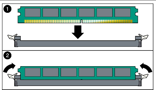
6. Press the top edge of the DIMM toward the blade server until the retainer clips click into place in the notches on the DIMM sides (FIGURE 2-6).
The small metal retainer clips on each side of the DIMM slot are spring-loaded, and they should click into place in the notches on the sides of the DIMM.
If you are returning the DIMM or the blade server for service, or if you are replacing a DIMM with another DIMM, remove the DIMM from the Sun Netra CP3250 blade server.
| Note - Safely store the original factory-shipped DIMM and related DIMM packaging. Store any removed DIMM in the new DIMM packaging. |
To remove a DIMM from the Sun Netra CP3250 blade server, perform the following steps:
1. Access the blade server by performing one of the following procedures:
If an ESD mat is not available, you can place the blade server on the antistatic envelope in which it was packaged.

|
Caution - Do not place blade servers on top of an antistatic bag unless the outside of the bag also has antistatic protective properties. |
2. Take antistatic precautions: Attach and electrically ground the wrist strap.

|
Caution - Always wear a grounded antistatic wrist strap when handling DIMMs. |
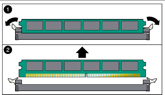
3. Simultaneously pull both spring retainer clips outward from the slot for the DIMM you want to remove.
4. Grasp the DIMM by the edges, and carefully pull it out of its connector.
Place it in an antistatic bag.
5. If you are replacing the DIMM you removed with a new DIMM, install it as described in Section 2.3.6.2, Installing a DDR2 DIMM.
An IDE Compact Flash card can be installed on the Sun Netra CP3250 blade server. The Compact Flash card is not hot-swappable, and there is no access to the Compact Flash card once the Sun Netra CP3250 blade server is installed in an ATCA shelf.
1. Access the blade server by performing one of the following procedures:
If an ESD mat is not available, you can place the blade server on the antistatic envelope in which it was packaged.

|
Caution - Do not place blade servers on top of an antistatic bag unless the outside of the bag also has antistatic protective properties. |
2. Push where indicated on door that provides access to the Compact Flash, then open the door.
FIGURE 2-8 shows the door.
FIGURE 2-8 Opening the Door to Access Compact Flash
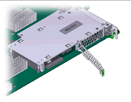
3. Locate the Compact Flash connector.
The connector is located on the blade server, behind the sheet metal door protecting the AMC slot B1 (FIGURE 2-9).
FIGURE 2-9 Compact Flash Location
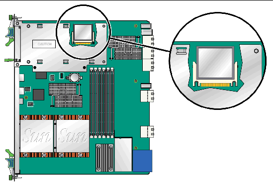
4. To install the Compact Flash card, use the arrow on the card as a guide to insert the card into the Compact Flash connector.
| Note - Sun Compact Flash cards have a life time of 2,000,000 write/erase cycles. Users are responsible for ensuring that the operating system and applications do not exceed this limitation. |
An Advanced Mezzanine card (AMC) is a card or module that provides additional functionality to the Sun Netra CP3250 blade server. The blade server contains one AMC slot in which you can install an optional AMC device. An AMC device can be installed and removed via a cutout in the front panel while the Sun Netra CP3250 blade server is installed in the chassis.
1. Retrieve the wrist strap from the shipping kit.
2. Attach the adhesive copper strip of the antistatic wrist strap to the metal chassis.
Wrap the other end twice around your wrist, with the adhesive side against your skin.
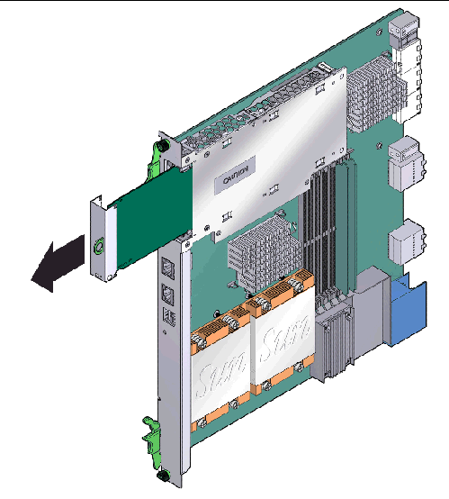
3. Remove the AMC slot filler panel from the blade server’s front panel (FIGURE 2-10).
FIGURE 2-10 Removing an AMC Filler Panel
4. Retrieve the AMC from its shipping kit and place it on an antistatic surface.
5. Insert the AMC through the cutout and into the AMC slot (FIGURE 2-11).
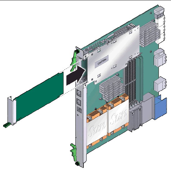
6. Carefully push the AMC into the AMC connector.
7. Refer to the AMC documentation for software and cabling installation instructions.
The Sun Netra CP3250 blade server does not ship with the battery. If you want CMOS settings to be preserved in the event of power loss, obtain and install the battery.
The battery must be type CR1632, with a minimum of 4ma abnormal charging current rating (for example; a Renata CR1632).

|
Caution - Risk of explosion if the battery is replaced by an incorrect type. Dispose of used batteries properly in accordance with manufacturer’s instructions and local regulations. |
1. Remove the old battery, if necessary.
2. Slide the new battery into the holder with the side labeled “+” facing up.
Jumpers and their switches are located near the heatsink on the blade server.
Reset jumper 2 to clear the CMOS settings, which restores the default BIOS settings.
Jumper 2 is shown in FIGURE 2-12. The jumper housing should be stored in the P2/P3 position, which is the run position.
FIGURE 2-12 Jumper 2 in the Default Run Position
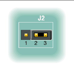
TABLE 2-4 provides information on the pin functions on jumper 2.
|
BATT_CLR (resistor to GND, used to drain capacitive charge and clear the CMOS memory) |
To reset the jumper and return the CMOS settings to the default settings, perform the following steps:
1. Remove the jumper housing from the run position (P2/32) and move it to the reset position (P1/P2).
2. Wait at least one second for the CMOS settings to reset and then move the jumper housing back to the run position (FIGURE 2-12).
3. Reinstall the blade server.
Use the procedure in Section 2.2.3.2, Installing the Blade Server Into the Shelf.
| Note - The blade server will operate normally only when the jumper housing is in the run position. |
The color of the Out-of-service (OOS) LED can be set to red or amber by moving jumper 13 to the appropriate position. Amber is the default color for the OOS LED.
To change the Jumper 13 position to display a red OOS LED:
1. Remove the jumper housing from the default (amber) position (P2/P3) and move it to the red position (P1/P2).
2. Reinstall the blade server.
Use the procedure in Section 2.2.3.2, Installing the Blade Server Into the Shelf.
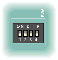
DIP switch settings are set by default at the factory. The following settings are required for normal operation of the blade server.
FIGURE 2-13 SW1 Default DIP Switch Settings
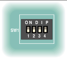
FIGURE 2-14 SW4 Default DIP Switch Settings
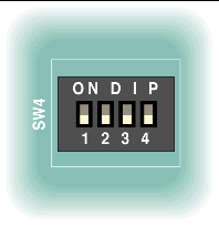
FIGURE 2-15 SW5 Default DIP Switch Settings
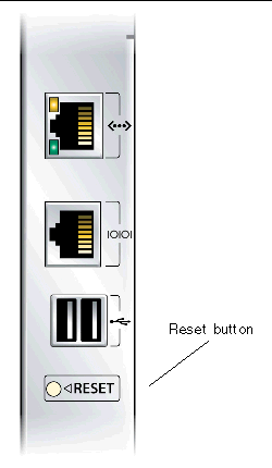
1. Use a spudger tool or other stylus to press and release the recessed Reset button on the front of the Sun Netra CP3250 blade server (FIGURE 2-16).
2. Confirm the progress of the reset by monitoring the BIOS POST messages.
FIGURE 2-16 Netra CP3250 Blade Server Front Panel
Copyright © 2009 Sun Microsystems, Inc. All rights reserved.