| C H A P T E R 5 |
|
Configuration Overview |
This chapter highlights the tools and the important limitations and guidelines which must be understood prior to configuring your array.
This chapter covers the following topics:
Subsequent chapters in this manual describe further procedures used to complete the installation and configuration of the arrays. The flexible architecture of Sun StorEdge 3510 FC arrays and Sun StorEdge 3511 SATA arrays makes many configurations possible.
Sun StorEdge 3510 FC arrays and Sun StorEdge 3511 SATA arrays are preconfigured with a single RAID 0 logical drive mapped to LUN 0, and no spare drives. This is not a usable configuration, but it enables in-band connections with management software. You must delete this logical drive and create new logical drives.
All configuration procedures can be performed by using the COM port. You can also perform all procedures except the assignment of an IP address through an Ethernet port connection to a management console.
The following steps describe the typical sequence of steps for completing a first-time configuration of the array.
1. Mount the array on a rack, cabinet, desk, or table.
2. Set up the serial port connection.
See Section 4.9.2, Configuring the RS-232 Serial Port Connection.
3. Set up an IP address for the controller.
See Section 4.9, Establishing Communications With An Array.
|
Note - For detailed information in performing steps 4-14, refer to the Sun StorEdge 3000 Family RAID Firmware User's Guide for optimization mode guidelines. |
4. Check the status of the available physical drives.
5. Determine whether sequential or random optimization is more appropriate for your applications and configure your array accordingly.
6. (Optional) Configure host channels as drive channels.
7. Confirm or change the Fibre Connection Option (point-to-point or loop).
8. Revise or add host IDs on host channels.
The IDs assigned to controllers take effect only after the controller is reset.
9. Delete default logical drives and create new logical drives.
10. (Optional) In dual-controller configurations only, assign logical drives to the secondary controller to load-balance the two controllers.
11. (Optional) Partition the logical drives.
12. Map each logical drive partition to an ID on a host channel, or apply a host LUN filter to the logical drives.
For information about different operating system procedures, see:
14. Save the configuration to a disk.
15. Make sure that the cabling from the RAID array to the hosts is complete.
|
Note - You can reset the controller after each step or at the end of the configuration process. |

|
Caution - Avoid using in-band and out-of-band connections at the same time to manage the array. Otherwise, conflicts between multiple operations can cause unexpected results. |
Remember the following guidelines when implementing point-to-point configurations in your array and connecting to fabric switches:
The controller displays a warning if the user is in point-to-point mode and tries to add an ID to the same channel but on the other controller. The warning is displayed because you have the ability to disable the internal connection between the channels on the primary and secondary controller using the Sun StorEdge CLI set inter-controller link command and, by doing this, you can have one ID on the primary and another ID on the secondary as a legal operation.
However, if you ignore this warning and add an ID to the other controller, the RAID controller does not allow a login as a Fabric Loop (FL) port because this would be illegal in a point-to-point configuration.
For example, to provide redundancy, map half of the LUNs across Channel 0 (PID 40) and Channel 4 (PID 42), and then map the other half of your LUNs across Channel 1 (SID 41) and Channel 5 (SID 43).
A point-to-point configuration has the following characteristics:
In a dual-controller array, one controller automatically takes over all operation of a second failed controller in all circumstances. However, when an I/O controller module needs to be replaced and a cable to an I/O port is removed, the I/O path is broken unless multipathing software has established a separate path from the host to the operational controller. Supporting hot-swap servicing of a failed controller requires the use of multipathing software, such as Sun StorEdge Traffic Manager software, on the connected servers.
Remember these important rules:
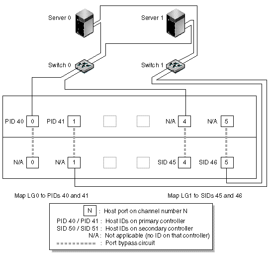
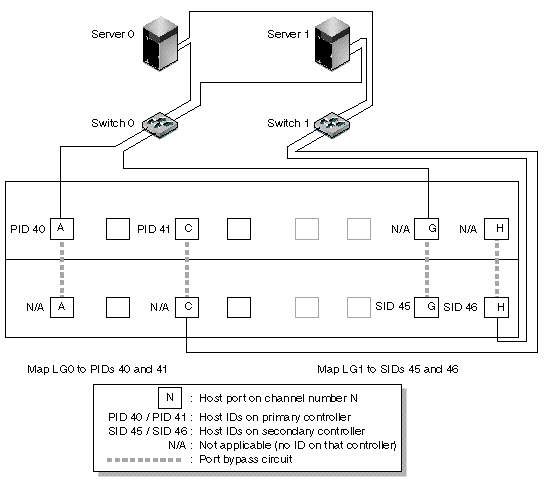
FIGURE 5-1 and FIGURE 5-2 show the channel numbers (0, 1, 4, and 5) of each host port and the host ID for each channel. N/A means that the port does not have a second ID assignment. The primary controller is the top I/O controller module, and the secondary controller is the bottom I/O controller module.
The dashed lines between two ports indicate a port bypass circuit that functions as a mini-hub. The port bypass circuit on each channel connects the upper and lower ports on the same channel and provides access to both controllers at the same time. If there are two host connections to the upper and lower ports on Channel 0, and one host connection is removed, the other host connection remains operational. Therefore, if you have a redundant multipathing configuration in which you have two host connections to each logical drive and one connection fails, the remaining path maintains a connection to the logical drive.
In FIGURE 5-1 and FIGURE 5-2, with multipathing software to reroute the data paths, each logical drive remains fully operational when the following conditions occur:


TABLE 5-1 summarizes the primary and secondary host IDs assigned to logical drives 0 and 1, as shown in FIGURE 5-1 and FIGURE 5-2.
Perform the following steps to set up a typical point-to-point SAN configuration based on FIGURE 5-1 and FIGURE 5-2.
1. Check the position of installed SFPs. Move them as necessary to support the connections needed.
2. Connect expansion units, if needed.
3. Create at least two logical drives (logical drive 0 and logical drive 1) and configure spare drives.
Leave half of the logical drives assigned to the primary controller (default assignment). Assign the other half of the logical drives to the secondary controller to load-balance the I/O.
4. Create up to 32 partitions (LUNs) in each logical drive.
5. Change the Fibre Connection Option to "Point to point only" ("view and edit Configuration parameters  Host-side Parameters
  Fibre Connections Option").
6. For ease of use in configuring LUNs, change the host IDs on the four channels to the following assignments:
Channel 0: PID 40 (assigned to the primary controller)
Channel 1: PID 41 (assigned to the primary controller)
Channel 4: SID 50 (assigned to the secondary controller)
Channel 5: SID 51 (assigned to the secondary controller)

|
Caution - Do not use the command, "Loop preferred, otherwise point to point." This command is reserved for special use and should be used only if directed by technical support. |
7. Map logical drive 0 to channels 0 and 1 of the primary controller.
Map LUN numbers 0 through 31 to the single ID on each host channel.
8. Map logical drive 1 to channels 4 and 5 of the secondary controller.
Map LUN numbers 0 through 31 to the single ID on each host channel. Since each set of LUNs is assigned to two channels for redundancy, the total working maximum number of LUNs is 64 LUNs.
|
Note - The LUN ID numbers and the number of LUNs available per logical drive can vary according to the number of logical drives and the ID assignments you want on each channel. |
9. Connect the first switch to ports 0 and 4 of the upper controller.
10. Connect the second switch to ports 1 and 5 of the lower controller.
11. Connect each server to each switch.
12. Install and enable multipathing software on each connected server.
The multipathing software prevents path failure but does not alter the controller redundancy through which one controller automatically takes over all functions of a second failed controller.
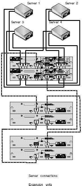
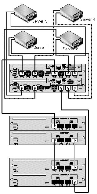
The typical direct attached storage (DAS) configuration shown in FIGURE 5-3 and FIGURE 5-4 includes four servers, a dual-controller array, and two expansion units. Expansion units are optional.
Servers, as shown in FIGURE 5-3 and FIGURE 5-4, are connected to the following channels:


Establishing complete redundancy and maintaining high availability requires the use of multipathing software such as Sun StorEdge Traffic Manager software. To configure for multipathing:
1. Establish two connections between each server and the array.
2. Install and enable multipathing software on the server.
3. Map the logical drive each server is using to the controller channels that the server is connected to.
DAS configurations are typically implemented using a fabric loop (FL_port) mode. A loop configuration example is described in Section 5.1.3, A Sample DAS Loop Configuration.
FL_port connections between a Sun StorEdge 3510 FC array or Sun StorEdge 3511 SATA array and multiple servers allow up to 1024 LUNs to be presented to servers. For guidelines on how to create 1024 LUNs, refer to the Sun StorEdge 3000 Family RAID Firmware User's Guide.
Perform the following steps to set up a DAS loop configuration as shown in FIGURE 5-3 and FIGURE 5-4.
1. Check the location of installed SFPs. Move them as necessary to support the connections needed.
You must add SFP connectors to support more than four connections between servers and a Sun StorEdge 3510 FC array or Sun StorEdge 3511 SATA array. For example, add two SFP connectors to support six connections and add four SFP connectors to support eight connections.
2. Connect expansion units, if needed.
3. Create at least one logical drive per server, and configure spare drives as needed.
4. Create one or more logical drive partitions for each server.
5. Confirm that the Fibre Connection Option is set to "Loop only."

|
Caution - Do not use the command, "Loop preferred, otherwise point to point." This command is reserved for special use and should be used only if directed by technical support. |
6. Set up to eight IDs on each channel, if needed (see TABLE 5-3).
7. Map logical drive 0 to channels 0 and 5 of the primary controller.
8. Map logical drive 1 to channels 1 and 4 of the secondary controller.
9. Map logical drive 2 to channels 0 and 5 of the primary controller.
10. Map logical drive 3 to channels 1 and 4 of the secondary controller.
11. Connect the first server to port FC 0 of the upper controller and port FC5 of the lower controller.
12. Connect the second server to port FC 4 of the upper controller and port FC1 of the lower controller.
13. Connect the third server to port FC 5 of the upper controller and port FC0 of the lower controller.
14. Connect the fourth server to port FC 1 of the upper controller and port FC4 of the lower controller.
15. Install and enable multipathing software on each connected server.
Except in some clustering configurations, if you connect more than one host to channel 0 or channel 1 in a DAS loop configuration, you must use host filtering when you want to control host access to storage. Refer to the Sun StorEdge 3000 Family RAID Firmware User's Guide for information about host filters. Refer to the user documentation for your clustering software to determine whether the clustering software can manage host access in this configuration.
Larger configurations are possible using additional expansion units connected to Sun StorEdge 3510 FC arrays or Sun StorEdge 3511 SATA arrays:
Certain limitations and considerations apply to these mixed configurations:
See Section 1.1, Comparison of Sun StorEdge 3510 FC Arrays and Sun StorEdge 3511 SATA Arrays for information about appropriate uses of these products to make sure the solutions you choose suit your applications and requirements.
For more detailed information, and for suggestions about the most appropriate configurations for your applications and environment, refer to the Sun StorEdge 3000 Family Best Practices Manual for your array.
Copyright © 2004, Sun Microsystems, Inc. All rights reserved.