| C H A P T E R 2 |
|
Installing Trays |
Use the procedures in this chapter to install trays in a cabinet or Telco rack. The number of trays you need to install depends on your overall storage requirements. You can install a maximum of eight, one controller tray and up to seven expansion trays, in a Sun cabinet or third-party Telco rack.
This chapter describes the process of installing Sun StorEdge 6130 trays. It contains the following sections:
The installation procedures in this chapter require the following items:
Use the following procedures to prepare for installation:
Unpack the rackmount kit and check the contents. The contents will vary, depending upon whether you ordered a kit for a cabinet installation or a Telco rack installation.
With a cabinet installation, the CAM100 3RU rail kit contains the following items:
The rails can be adjusted to fit the following Sun cabinets:
With a Telco rack installation, kits contain the following items:

2. Check the contents of the box for the following items:
Select the cabinet in which you will be installing the array. Be sure the cabinet is installed as described in the installation instructions provided with it.
1. Stabilize the cabinet as described in the cabinet documentation.
2. If the cabinet has casters, make sure the casters are locked to prevent the cabinet from rolling.
3. Remove or open the top front panel.
4. Remove or open the vented back panel.
Select the rack in which you will be installing the tray. The Telco mounting rails are designed to fit two types of racks:
Install the rack as described in the installation instructions provided by the manufacturer.
Install the trays starting with the first controller tray at the bottom of the cabinet. Next install the expansion trays for the first controller tray. If room remains in the cabinet, repeat for the next controller and expansion trays.
Starting at the bottom distributes the weight correctly in the cabinet.
Depending on the type of Sun cabinet you have, use one of the following procedures to attach the rails:
Because this rail kit can be adapted for several cabinets, closely follow the procedures; they may require actions you have not previously taken.
|
Note - In this section, you will loosely hang the rails from screws you attach to the side walls, before connecting the rails to the front and back. |
The procedure for attaching the rails to the Sun StorEdge Expansion cabinet and Sun Fire cabinet are the same, with one exception. For the Sun Fire cabinet, the rail extensions are not required and the following procedure instructs you to remove the screws and the extension from each rail.
|
Note - All of the drawings show the Sun StorEdge Expansion cabinet. |
1. Depending on the type of cabinet you have, do one of the following:
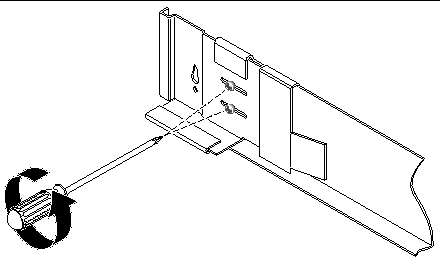
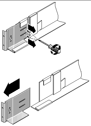
2. Insert four 10-32 screws (two per side) in the front and back mounting holes of the cabinet (FIGURE 2-3). Do not tighten at this time. You will hang the side rails on these screws.
Use the numbered marks on the inside of the cabinet to be sure that all four screws are aligned and mounted at the same height. Use hole 10 for the first tray and hole 19 for the second.
3. Locate the proper mounting holes by using the rack alignment template for the Sun StorEdge Expansion and Sun Fire cabinet (FIGURE 2-3).
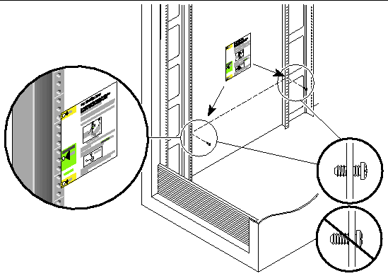
4. Place the template over the front left rail inside the cabinet.
5. Slide the template up and down until all three holes line up with the cabinet rail holes.
6. Note the screw hole number of the mounting hole that will be used by the keyhole slots in the rail (FIGURE 2-4).
You will use the same screw hole number for the front and back mounting holes on the left and right sides inside the cabinet.
7. Hang the left rail by aligning the large slots of the rail over the front and back screws and then pulling the rail down so that each screw is at the top of the slot (FIGURE 2-4). Repeat for the right rail.
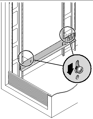
8. For the Sun StorEdge Expansion cabinet, adjust the length of each rail to fit the cabinet.
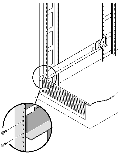
9. Using the #2 Phillips screwdriver, insert two 8-32 screws in the front of the left rail to secure the rail to the front of the cabinet (FIGURE 2-5). Repeat for the right rail.
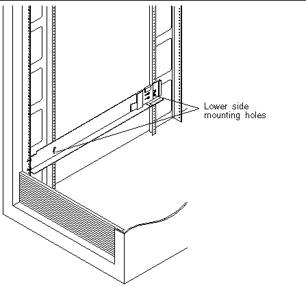
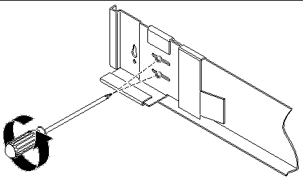
10. Using the #2 Phillips screwdriver, insert two 10-32 screws in the lower side mounting holes of the side rails (FIGURE 2-6). Use hole 8 for the first tray and hole 11 for the second tray. Repeat for the right rail.
11. Tighten all screws on the left and right rails.
1. Using the #2 Phillips screwdriver, loosen the side-rail screws and adjust each rail to its maximum length (FIGURE 2-7).
2. Locate the proper mounting holes by placing the rack alignment template for the Sun Rack 900/1000 cabinet over the front left cabinet rail (FIGURE 2-8).
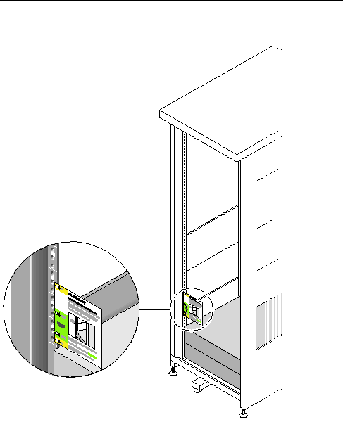
3. Slide the template up and down until all four holes line up with the cabinet rail holes.
4. Note the screw hole numbers of the two mounting holes.
You will use the same screw hole numbers for the rest of this installation.
5. Using the #2 Phillips screwdriver, insert and tighten two 8-32 screws to secure the the left rail to the front of the cabinet (FIGURE 2-9). Repeat for the right rail.
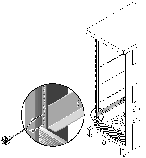
6. At the back of the cabinet, adjust the length of each rail as needed to fit the cabinet, and position the rail flange over the vertical rail (FIGURE 2-10).
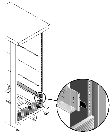
7. Using the #3 Phillips screwdriver, insert and tighten the M6 screws on each side at the back of the rail (FIGURE 2-11).
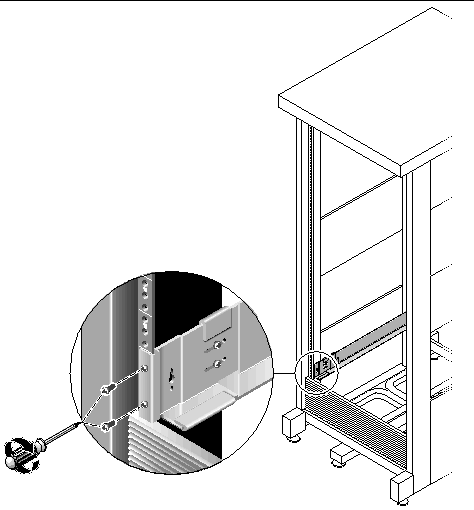
8. Using the #2 Phillips screwdriver, tighten the four adjusting screws (two on each side) toward the back of each rail (FIGURE 2-12).
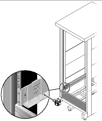
Install the controller tray in the first empty slot at the bottom of the cabinet. If you are installing expansion trays, continue installing the trays from the bottom up.
After installing each tray, you must connect its power cables and set the tray ID as described on page 52.
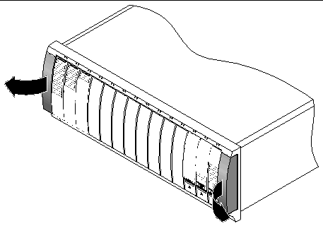
1. Unsnap and remove the left and right end caps on the array to permit access to the screw mounting holes (FIGURE 2-13).
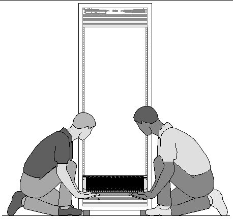
2. Using two people, one at each side of the array, carefully lift and rest the array on the bottom ledge of the left and right rails (FIGURE 2-14).

|
Caution - Use care to avoid injury. An array can weigh up to 95 pounds (45 kg). |
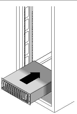
3. Carefully slide the array into the cabinet until the front flanges of the array touch the vertical face of the cabinet (FIGURE 2-15).
4. Depending on the type of cabinet you have, do one of the following:
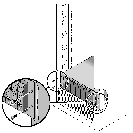
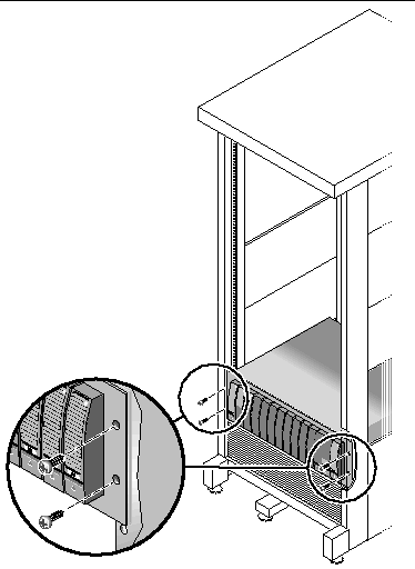
5. Replace the left and right end caps to hide the front mounting screws.
The end caps snap onto the front bezel of the tray.
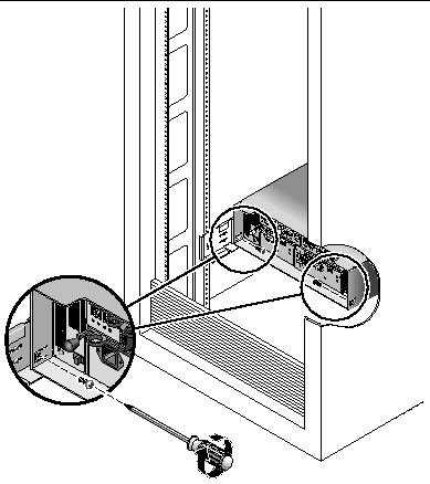
6. At the back of the tray, install and tighten two 8-32 screws (one per side) to secure the back of the array to the cabinet (FIGURE 2-18).
Depending on the type of Telco rack you have, use one of the following procedures to attach the rails:
Because this rail kit can be adapted for several cabinets, closely follow the procedures; they may require actions you have not previously taken.
|
Note - In this section, you will loosely hang the rails from screws you attach to the side walls, before connecting the rails to the front and back. |
This procedure describes how to attach the rackmount rail kit to a Telco 2-post
3-inch width "C" channel frame.
You will mount each tray with its horizontal center aligned with the frame of the Telco 2-post rack.
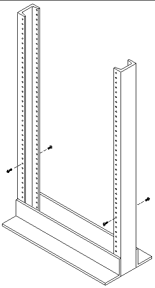
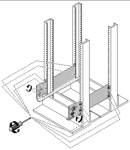
1. Insert four 12-24 screws (two in each post) in the front and back mounting holes of the left and right posts (FIGURE 2-19). Do not tighten at this time.
Use the lowest available mounting holes at the bottom of each post. Make sure that all four screws are aligned and mounted at the same height.
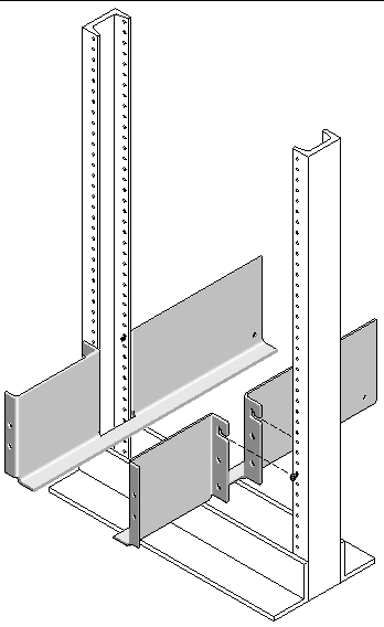
2. Align the open slot of the left mounting rail over the front and back screws of the left post, and press the rail down until it is seated over the screws (FIGURE 2-20). Repeat for the right rail.
3. Insert eight 12-24 screws (four in each post) in the lower mounting holes at the front and back of the left and right rails (FIGURE 2-21).
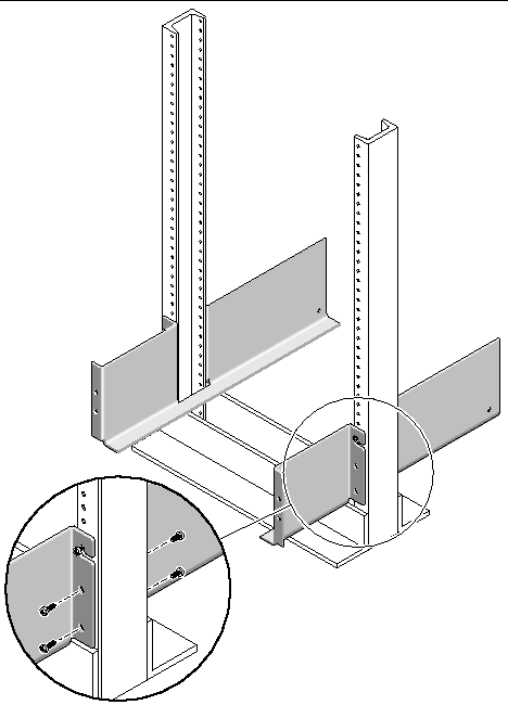
4. Using the #3 Phillips screwdriver, tighten all twelve screws (six on each side) at the front and back of both mounting rails to secure each rail to its post (FIGURE 2-22).
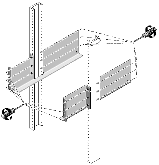
This procedure describes how to attach the rackmount rail kit to a Telco 4-post
3-inch "C" rack. You can adjust the mounting rails to allow for a 12-inch to 14-inch space between the front and back posts.
1. Insert eight 12-32 screws (two in each post) in the back mounting holes of the left and right posts (FIGURE 2-23). Do not tighten at this time.
Use the lowest available mounting holes at the bottom of each post. The screws in the back posts will be slightly lower than the screws in the front posts.
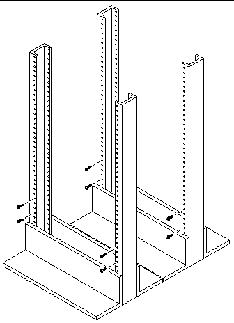
2. Loosen, but do not remove, the two hand knobs on the adjustable bracket at the back of the left rail. Align the back bracket of the left mounting rail so it fits against the back post, and then tighten the two knobs (FIGURE 2-24). Repeat for the right rail.
3. Align the open slot of the left mounting rail over the front and back screws of the left post, and press the rail down until it is seated over the screws (FIGURE 2-24). Repeat for the right rail.
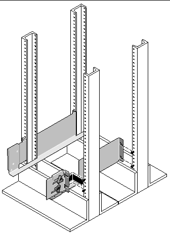
4. Tighten the eight screws (four per side) at the front and back of both mounting rails to secure each rail to its post (FIGURE 2-25).
Use the following procedures to install a tray in Telco 2-post or 4-post rack:
Be sure to install the controller tray in the first empty slot at the bottom of the cabinet. If you are installing expansion trays, continue installing the trays from the bottom up. After installing each tray, you must connect the power cables and set the tray ID as described on page 52.
When installing a tray in a Telco 2-post rack, follow these instructions:
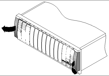
1. Unsnap and remove the left and right end caps on the tray to permit access to the screw mounting holes (FIGURE 2-26).
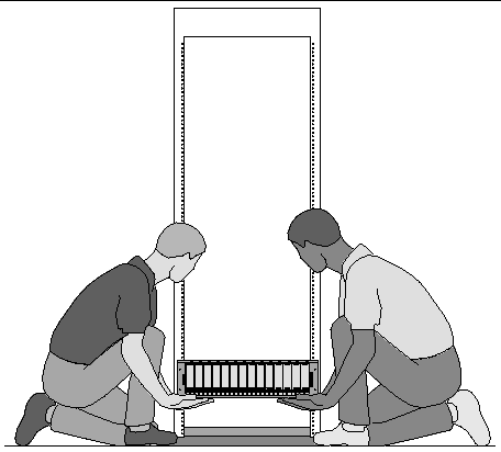
2. Using two people, one at each side of the tray, carefully lift and rest the tray on the bottom ledge of the left and right rails (FIGURE 2-27).

|
Caution - Use care to avoid injury. An tray can weigh up to 95 pounds (45 kg). |
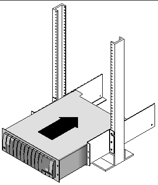
3. Carefully slide the tray onto the mounting rails until the front bezel of the tray contacts the rail flange on each side (FIGURE 2-28).
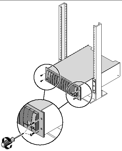
4. Use the #2 Phillips screwdriver to insert and tighten four 10-32 screws (two per side) to secure the tray to the front of the rack (FIGURE 2-29).
5. Replace the left and right end caps to hide the front mounting screws.
The end caps snap onto the front bezel of the tray.
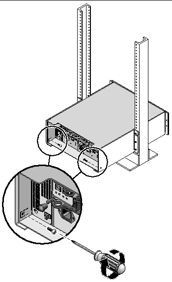
6. At the back of the tray, use the #2 Phillips screwdriver to install and tighten two
8-32 screws (one per side) through the back mounting points (FIGURE 2-30).
When installing a tray in a Telco 4-post rack, follow these instructions:
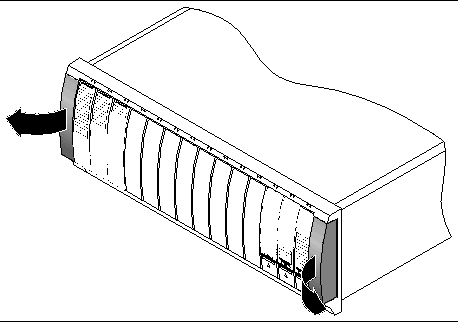
1. Unsnap and remove the left and right end caps on the tray to permit access to the screw mounting holes (FIGURE 2-31).
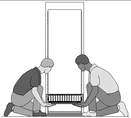
2. Using two people, one at each side of the tray, carefully lift and rest the tray on the bottom ledge of the left and right rails (FIGURE 2-32).

|
Caution - Use care to avoid injury. A tray can weigh up to 95 pounds (45 kg). |
3. Carefully slide the tray onto the mounting rails until the front bezel of the tray contacts the rail flange on each side (FIGURE 2-33).
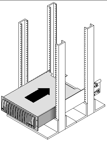
4. Use the #2 Phillips screwdriver to insert and tighten four 10-32 screws (two per side) to secure the tray to the front of the rack (FIGURE 2-34).
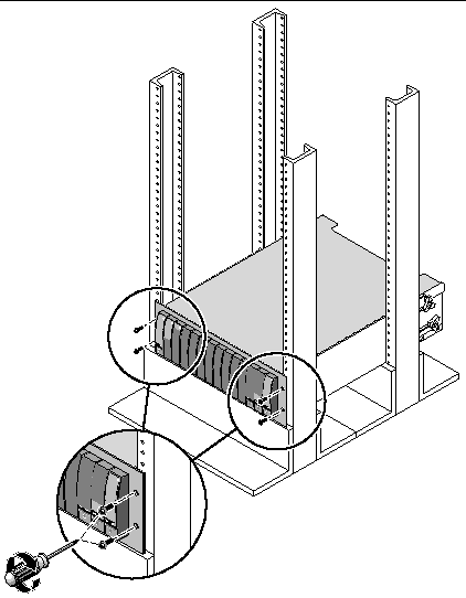
5. Replace the left and right end caps to hide the front mounting screws.
The end caps snap onto the front bezel of the tray.
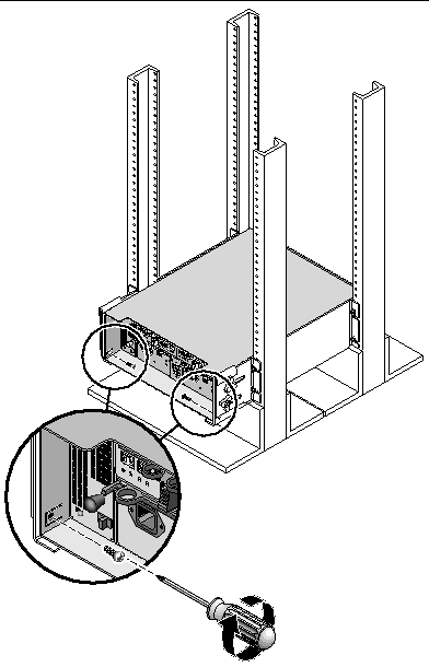
6. At the back of the tray, use the #2 Phillips screwdriver to install and tighten two
8-32 screws (one per side) through the back mounting points (FIGURE 2-35).
1. Verify that both power switches are off for each tray in the cabinet.
2. Connect each power supply in the tray to a separate power source in the cabinet.
3. Connect the primary power cables from the cabinet to the external power source.
|
Note - Do not power on the array until you complete the procedures in this chapter. The power-on sequence is described in detail in Chapter 3. |
You set the tray ID using the Tray ID switch at the back of the controller tray. You must set the tray ID of each tray to a unique number from 00 to 77.
1. Locate the Tray ID switch at the back of the controller tray, between the two power supplies (FIGURE 2-36).
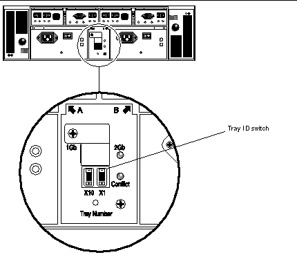
2. Use a pen tip to press the plus and minus buttons on the X10 and X1 switch to the appropriate setting.
The X10 switch at the left sets the tens place of the tray ID, and the X1 switch sets the ones place. For example, to set the tray ID to 11, set the X10 switch to 1 and the X1 switch to 1.
By convention, tray ID 00 refers to the controller tray. The first expansion tray located above the controller tray is tray ID 01. The second expansion tray is tray ID 02. The tray ID increments by 01 for each expansion tray installed in the cabinet.
When you have finished installing all trays, connecting their power cables, and setting their tray IDs, you are ready to connect the controller array to the expansion trays as described in the next section.
This section describes how to cable a controller tray to expansion trays for several different configurations. The controller tray uses Controller A and Controller B expansion ports to connect to FC-AL ports at the back of an expansion tray (FIGURE 2-37).
The configuration naming convention is "controllers x trays" where the first number is the controller tray and the second is the total number of trays. For example, 1x1 is a standalone controller tray, 1x2 is one controller tray and one expansion tray, and 1x8 is one controller tray and 7 expansion trays (TABLE 2-1).
Use the following instructions to connect the dual-RAID controller tray to one or more expansion trays. Interconnection cabling instructions are provided for 1x2, 1x3, 1x4, and 1x8 configurations. You can also use these instructions as a guide for cabling 1x5, 1x6, and 1x7 configurations.
A 1x2 array configuration consists of one controller tray and one expansion tray. Two 2-meter copper FC cables are required (530-3327-01).
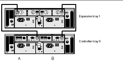
1. Locate the Controller A side and B side expansion ports at the back of the controller tray (FIGURE 2-37).
2. Locate the Controller A side and B side FC-AL ports 1 and 2 at the back of the expansion tray (FIGURE 2-37).
3. Connect one FC cable between the A side expansion port of the controller tray and the A side port 1 of the expansion tray (FIGURE 2-38).
4. Connect one FC cable between B side expansion port of the controller tray and the B side port 2 of the expansion tray (FIGURE 2-38).
|
Note - The A side port 2 and B side port 1 of expansion tray 1 remain empty. |
A 1x3 array configuration consists of one controller tray and two expansion trays. Four 2-meter copper FC cables are required (530-3327-01).
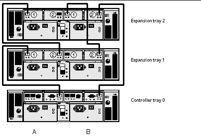
1. Locate the Controller A side and B side expansion ports at the back of the controller tray (FIGURE 2-37).
2. Locate the Controller A side and B side FC-AL ports 1 and 2 at the back of each expansion tray (FIGURE 2-37).
3. Connect one FC cable between the A side expansion port of controller tray 0 and the A side port 1 of expansion tray 1 (FIGURE 2-39).
4. Connect one FC cable between the A side port 2 of expansion tray 1 and the A side port 1of expansion tray 2 (FIGURE 2-39).
5. Connect one FC cable between the B side expansion port of controller tray 0 and the B side port 2 of expansion tray 2 (FIGURE 2-39).
6. Connect one FC cable between the B side port 1 of expansion tray 2 and the B side port 2 of expansion tray 1 (FIGURE 2-39).
|
Note - The A side port 2 of expansion tray 2 and the B side port 1 of expansion tray 1 remain empty. |
A 1x4 array configuration consists of one controller tray and three expansion trays. Six 2-meter copper FC cables are required (530-3327-01).
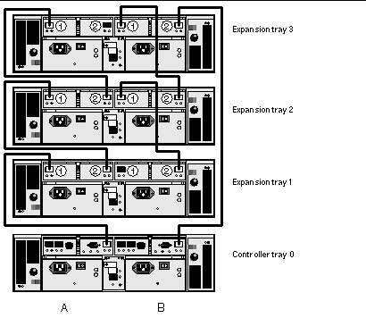
1. Locate the Controller A side and B side expansion ports at the back of the controller tray (FIGURE 2-37).
2. Locate the Controller A side and B side FC-AL ports 1 and 2 at the back of each expansion tray (FIGURE 2-37).
3. Connect one FC cable between the A side expansion port of controller tray 0 and the A side port 1 of expansion tray 1 (FIGURE 2-40).
4. Connect one FC cable between the A side port 2 of expansion tray 1 and the A side port 1 of expansion tray 2 (FIGURE 2-40).
5. Connect one FC cable between the A side port 2 of expansion tray 2 and the A side expansion port 1 of expansion tray 3 (FIGURE 2-40).
6. Connect one FC cable between the B side expansion port of controller tray 0 and B side port 2 of expansion tray 3 (FIGURE 2-40).
7. Connect one FC cable between the B side port 1 of expansion tray 3 and the B side port 2 of expansion tray 2 (FIGURE 2-40).
8. Connect one FC cable between the B side port 1 of expansion tray 2 and the B side port 2 of expansion tray 1 (FIGURE 2-40).
|
Note - The A side port 2 of expansion tray 3 and the B side port 1 of expansion tray 1 remain empty. |
A 1x8 array configuration consists of one controller tray and seven expansion trays. Fourteen 2-meter copper FC cables are required (530-3327-01).
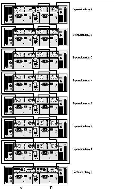
1. Locate the Controller A side and B side expansion ports at the back of the controller tray (FIGURE 2-37).
2. Locate the Controller A side and B side FC-AL ports 1 and 2 at the back of each expansion tray (FIGURE 2-37).
3. Connect one FC cable between the A side expansion port of controller tray 0 and the A side port 1 of expansion tray 1 (FIGURE 2-41).
4. Connect one FC cable between the A side port 2 of expansion tray 1 and the A side port 1 of expansion tray 2 (FIGURE 2-41).
5. Continue to connect one FC cable between the A side port 2 of each expansion tray and the A side port 1 of the expansion tray directly above it, until the A sides of all expansion trays are interconnected with FC cables (FIGURE 2-41).
6. Connect one FC cable between the B side expansion port of controller tray 0 and the B side port 2 of expansion tray 7 (FIGURE 2-41).
7. Connect one FC cable between the B side port 1 of expansion tray 7 and the B side port 2 of expansion tray 6 (FIGURE 2-41).
8. Continue to connect one FC cable between the B side port 1 of each expansion tray and the B side port 2 of the expansion tray directly below it, until the B sides of all expansion trays are interconnected with FC cables (FIGURE 2-41).
|
Note - The A side port 2 of expansion tray 7 and the B side port 1 of expansion tray 1 remain empty. |
After you cable all of the trays, you can power on the trays, as described in Chapter 3.
Copyright © 2004, Sun Microsystems, Inc. All Rights Reserved.