C H A P T E R  1

Overview

This chapter provides an overview of the Sun StorEdge 6130 array. It contains the following sections:


Product Overview

The Sun StorEdge 6130 array is a high-performance, enterprise-class, full 2 Gigabit per second (Gb/s) Fibre Channel solution that combines outstanding performance with the highest reliability, availability, flexibility, and manageability.

The Sun StorEdge 6130 array is modular, rackmountable and scalable from a single controller tray (1x1) configuration to a maximum configuration of 1x8 with seven additional expansion modules behind one controller tray (FIGURE 1-1).

This section contains an overview of the Sun StorEdge 6130 array hardware and software.


FIGURE 1-1 Sun StorEdge 6130 Array Product Overview

Figure showing a sample Sun StorEdge 6130 array configuration. [ D ]


Hardware Overview

The Sun StorEdge 6130 array is a modular storage device that can scale from one controller tray to an array with a maximum of eight modules, consisting of one controller tray and seven expansion modules. Each controller or expansion tray can contain 5 to 14 disk drives per tray. The StorEdge 6130 arrays can be installed in the Sun StorEdge Expansion, Sun Fire System, and Sun Rack 900 /1000 cabinets, as well as in a third-party Telco 2-post or 4-post rack.

This section describes the main components of the Sun StorEdge 6130 array controller and expansion trays.

Controller Tray

A controller tray contains two RAID controllers, which operate independently and provide failover capability for the management path. The controller tray is configured for Fibre Channel (FC) disk drives and provides RAID functionality, caching, and disk storage.

TABLE 1-1 describes the controller tray configuration.


TABLE 1-1 Sun StorEdge 6130 Array Controller Tray

Description

Quantity

FC RAID controllers

2

FC 3.5-inch drives

5 - 14 per tray

FC hard disk drives: 73G10K, 73G15K, 146G10K

Ethernet ports for management host connections

2 (1 per controller)

2-Gbps FC host ports with SFPs

4 (2 per controller)

2-Gbps FC expansion ports

2 (1 per controller)

Power supplies

2

Fan assemblies

2


FIGURE 1-2shows the components and indicators on the front of the controller tray.FIGURE 1-2 Controller Tray (Front View)

Figure showing a front view of the controller module.[ D ]


TABLE 1-2 describes the LEDs and switches on the front of the controller tray.


TABLE 1-2 Controller Tray LEDs and Switches (Front)

LED/Switch

Description

Drive set ID/Fault LED

This LED is steady amber to indicate a drive fault and blinks amber to indicate drive position identification.

Drive in place/Active LED

This LED is steady green for each drive that is in place and blinks green to indicate disk activity.

Power LED

This LED is steady green when at least one power supply is installed and functional.

Summary fault LED

This LED is amber when a tray level fault occurs.


FIGURE 1-3shows the ports and switches at the back of the controller tray. You will use these during the installation procedure.FIGURE 1-3 Controller Tray Ports and Switches (Back View)

Figure showing a back view of the controller module. [ D ]


TABLE 1-3 describes the ports and switches on the back of the controller tray.


TABLE 1-3 Controller Tray Ports and Switches (Back)

Ports/Switches/LEDs

Description

Host 1 and 2 ports

2-Gbit FC Small Form-factor Plug-in (SFP) ports used to connect to data hosts.

Ethernet ports

RJ-45 Ethernet port used for out-of-band management of the RAID controller. An internal Ethernet device provides standard 10 Mbits/second and 100 Mbits/second full-duplex connectivity.

Expansion ports (Out)

2-Gbit FC ports used to connect to the drive channel device and expansion modules.

Tray ID switch

A pair of rotary switches used to select the array's tray number. One switch sets the tens place, and the other sets the ones place.

Rate select switch

A toggle switch used to set the transfer rate of the FC disk drive loop to 1 Gbit/second or 2 Gbits/second.


FIGURE 1-4shows the LEDs at the back of the controller tray. You will also use these during the installation procedure.FIGURE 1-4 Controller Tray LEDs (Back View)

Figure showing a back view of the controller module. [ D ]


TABLE 1-4 describes the LEDs on the back of the controller tray.


TABLE 1-4 Controller Tray LEDs (Back)

LED

State/Color

Cause and Action

Connection Active/
Not Active LED
(on Ethernet connector)

On/Green

There is an active connection.

No action is needed.


Off

No active connection.

Ensure that you have two active connections to the controller module.

100BaseTX Indicator
(on Ethernet connector)

On/Green

100BaseTX connection.

No action is needed.


Off

10BaseT connection, if Connection Active/Not Active LED is on.

No action is needed.

Host Connector 1/

Host Connector 2 Link LEDs

On/Green

Host connection is functioning normally.

No action is needed.


Off

No host is attached, or a problem is detected.

If a host is attached, check logs for errors.

Host Connector 1/

Host Connector 2 Speed LEDs

On/Green

2 Gb/s data rate from the host is detected.

No action is needed.


Off

1 Gb/s data rate from the host is detected.

To change the rate, refer to Checking the Link Rate LED.

Power Supply Power LED

On/Green

The module is receiving power.

No action is needed.


Off

The module is not receiving power.

Check the status of the Power Supply Fault LED.

Power Supply Fault LED

On/Amber

There is a problem with the power supply.

Check logs for errors.


Off

Power is off, or power supply is functioning normally.

No action is needed.

Drive Link LED

On/Green

Drive link is functioning normally.

No action is needed.


Off

A problem is detected inside the internal drive loop of the controller module.

Check logs for errors.

Expansion Port Bypass LED

On/Amber

There are no expansion trays present.


If expansion trays are present, a loop problem exists between the expansion and controller trays.


Off

Normal state. No action is needed.

2 Gb Link Rate LED

On/Green

The FC loop rate between trays is 2 Gb/s.


Off

The FC disk drive loops are operating at 1 Gb/s. Set the link rate to 2 Gb/s as described in Checking the Link Rate LED.

Tray ID Conflict LED

On/Amber

Two or more trays have the same ID.

Check for other amber LEDs and set correctly.


Off

No action is needed.

Battery Charging/ Charged LED


On/Green

Battery is charged.

No action is needed.


Blinking/Green

Battery is charging.

No action is needed.


Off

There is a problem with the battery.

Check logs for errors.

Cache Active LED

On/Green

Cache is in use. There is data in the cache that has not yet been written to disk.

No action is needed.


Off

There is no data in the write cache.

Fan LED

On/Amber

There is a problem with the fan.

Check logs for errors.


Off

No action is needed.

Fault LED

On/Amber

Indicates a general fault.

Check the states of other LEDs that indicate a fault. For example, if the Fan LED is on and amber, then the Fault LED should be on, too. Also check logs for errors.


Off

Power is off, or module is functioning normally.

No action is needed.


Expansion Tray

The expansion tray provides from 5 to 14 additional FC or Serial Advanced Technology Attachment (SATA) drives. An expansion tray is cabled directly to a controller tray and cannot operate independently.

You cannot mix FC and SATA disk drives within the same expansion tray. All drives within a single expansion tray must be the same type, either all FC drives or all SATA drives.

TABLE 1-5 describes the expansion tray components.


TABLE 1-5 Sun StorEdge 6130 Array Expansion Tray

Description

Quantity

FC or SATA 3.5-inch drives

FC hard disk drives: 73G10K, 73G15K, 146G10K

5 - 14


SATA hard disk drives: 400G7.2


I/O tray with In and Out expansion ports

2

Power supplies

2

Fan assemblies

2


TABLE 1-6 describes the expansion tray LEDs.


TABLE 1-6 Expansion Tray LEDs (Back)

LED

State/Color

Cause and Action

Bypass In LED

On/Amber

No cable is connected.


Off

Cable is connected.

Power LED

On/Green

The module is receiving power.

No action is needed.


Off

The module is not receiving power.

Fault LED

On/Amber

Indicates a general fault.

Check the states of other LEDs that indicate a fault. For example, if the Fan LED is on and amber, then the Fault LED should be on, too. Also check logs for errors.


Off

Power is off, or module is functioning normally.

No action is needed.

Over Temp LED

On/Amber

Indicates an overheating problem.


Off

Module is functioning normally.

No action is required.

Bypass Out LED

On/Amber

No cable is connected.


Off

Cable is connected.

Fan LED

On/Amber

There is a problem with the fan.

Check logs for errors.


Off

No action is needed.

Power Supply Power LED

On/Green

The module is receiving power.

No action is needed.


Off

The module is not receiving power.

Check the status of the Power Supply Fault LED.

Power Supply Fault LED

On/Amber

There is a problem with the power supply.

Check logs for errors.


Off

Power is off, or power supply is functioning normally.

No action is needed.


FIGURE 1-5 shows the front and back views of the expansion tray LEDs for a SATA drive. FIGURE 1-6 shows the front and back views of the expansion tray LEDs for an FC drive.
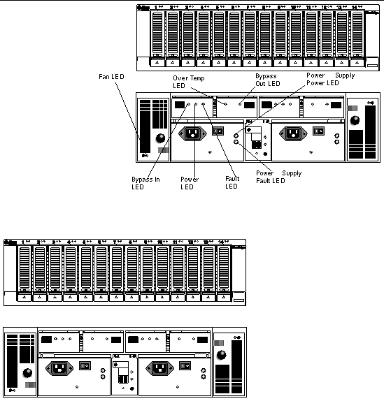
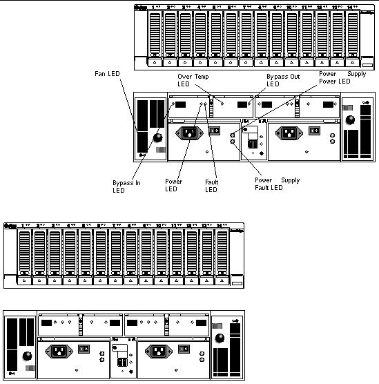
FIGURE 1-5 SATA Expansion Tray (Front and Back Views))

Figure showing the front and back views of an expansion module.


FIGURE 1-6 FC Expansion Tray (Front and Back Views)

Figure showing the front and back views of an expansion module.


Software Overview

The Sun StorEdge 6130 array software is delivered on CD and consists of the tools described in the following topics:

You specify the functionality you require, and the CD installs the necessary software.

Management Software

The Sun StorEdge 6130 array web-based management software is the primary interface for configuring and managing the array. The management software consists of a suite of tools that you install on an external management host, including the command line interface (CLI). The management host must be a Sun workstation running the Solaris 8, 9, and 10 Operating System (OS).

The management software enables the storage administrator to manage the Sun StorEdge 6130 array from any system with a web browser that is on the same network as the management host. For a list of supported browsers, see the Sun StorEdge 6130 Array Release Notes.

Remote CLI Client

You can also manage and configure storage for the Sun StorEdge 6130 array using the remote CLI client. The CLI provides the same control and monitoring capability as the web browser, and it is also scriptable for running frequently performed tasks.

The remote CLI client is available for Solaris OS and several other operating systems. See the Sun StorEdge 6130 Array Release Notes for a list of supported operating system platforms. For more information about the CLI commands, see the sscs man page.

Monitoring and Diagnostic Software

The Sun Storage Automated Diagnostic Environment (StorADE) is a monitoring and diagnostic tool for the array. You can configure the software to monitor on a 24-hour basis, collecting information that enhances the reliability, availability, and serviceability (RAS) of the Sun StorEdge 6130 array. For additional information, see the Storage Automated Diagnostic Environment Enterprise Edition Release Notes.

The monitoring and diagnostic software can be accessed from a web browser or from the command line.

Data Host Software

The Sun StorEdge 6130 array data host software controls the data path between the data host and the array. The data host software consists of the following tools:

Data host software enables Solaris 8, 9, and 10 workstations and other operating system platforms to communicate with the Sun StorEdge 6130 array. For a list of supported operating system platforms, see the Sun StorEdge 6130 Array Release Notes.

Data host software for Solaris is distributed on the Sun StorEdge 6130 Host Installation Software CD. See Chapter 7 for information about how to obtain the software for other operating systems from Sun's Download Center.


Overview of the Installation Process

Before you begin to install the array, you must do the following:

You can download the Sun StorEdge documentation from:

http://www.sun.com/products-n-solutions/hardware/docs/Network Storage Solutions/Midrange/6130/index.html

The following checklist (TABLE 1-7) outlines all of the tasks required for installing the Sun StorEdge 6130 array hardware and software and tells you where you can find detailed procedures. To ensure a successful installation, perform the tasks in the order in which they are presented.


TABLE 1-7 Sun StorEdge 6130 Array Installation Checklist

Step

Installation Task

Where to Find Procedure

  1.  

Unpack the cabinet and move it into position.

Unpacking guide attached to the outside of the shipping carton

  1.  

Install and secure the cabinet.

Sun StorEdge Expansion Cabinet Installation and Service Manual,

Sun Rack Installation Guide, or

Sun Fire Cabinet Installation and Reference Manual

  1.  

Unpack the rackmounting kit and check its contents.

Preparing the Rackmount Kit

  1.  

Unpack the tray box and check its contents.

Preparing the Tray

  1.  

Prepare the cabinet for installation.

Preparing the Cabinet

  1.  

Attach the rails to the cabinet or Telco rack.

Attaching the Rails to the Sun StorEdge Expansion or Sun Fire Cabinet,

Attaching the Rails to the Sun Rack 900/1000 Cabinet,

Attaching the Rails to a Telco 2-Post Rack, or

Attaching the Rails to a Telco 4-Post Rack

  1.  

Mount the controller tray and expansion trays in the cabinet or Telco rack.

Installing a Tray in a Cabinet, or Installing a Tray in a Telco Rack

  1.  

Attach the power cables.

Connecting the Power Cables

  1.  

Set the tray ID.

Setting the Tray ID

  1.  

Cable the controller tray and expansion trays.

Intertray Cabling

  1.  

Turn on the power and check the link rate.

Powering On Trays

  1.  

Connect the management host.

Connecting the Management Host

  1.  

Attach the host interface cables.

Connecting Data Hosts

  1.  

Install the management software.

Running the Installation Script

  1.  

Configure the controller tray IP addresses.

Configuring the IP Address of the Array Controllers

  1.  

Start and log in to the management software.

Starting the Management Software

  1.  

Set initial array settings.

Setting Up the Management Software

  1.  

Set initial Storage Automated Diagnostic Environment settings.

Setting Up the Sun Storage Automated Diagnostic Environment

  1.  

Connect Sun Remote Services Net Connect.

Connecting Sun SRS Net Connect 3.1

  1.  

Install the data host software.

Installing Data Host Software

  1.  

Install the remote CLI software.

Installing Remote Management Software

  1.  

Start to configure your storage.

Planning Your Storage Configuration