| C H A P T E R 3 |
 Replacing Storage Components
 |
This chapter provides instructions for replacing nonvolatile data storage components. Topics include:
The hard drives in the server are hot-pluggable, but this capability depends on how the hard drives are configured. To hot-plug a drive you must be able to take the drive offline before you can remove it. Prevent any applications from accessing the drive and remove the logical software links to it.
The following situations inhibit the ability to perform hot-plugging of a drive:
If your drive falls into one of these conditions, you must shut the system down before you replace the hard drive. See Powering Off the Server.
| Note - Replacing a hard drive does not require removing the server from a rack. |
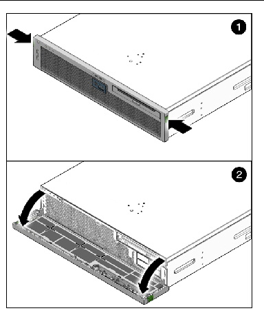
1. Press the green tabs on either side of the bezel and pull forward and down (FIGURE 3-1).
2. Identify the location of the hard drive that you want to remove (FIGURE 3-2 and FIGURE 3-3).
FIGURE 3-2 Locations of HDDs on 2 HDD Server

FIGURE 3-3 Locations of HDDs on 4 HDD Server

3. Type the Solaris OS commands required to stop using the hard drive.
Exact commands required depend on the configuration of your hard drives. You might need to unmount file systems or perform RAID commands.
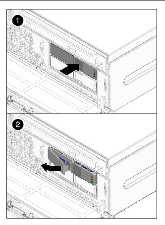
4. On the drive you plan to remove, push the latch release button (FIGURE 3-4).
FIGURE 3-4 Opening Hard Drive Latch

|
Caution - The latch is not an ejector. Do not bend it too far to the left. Doing so can damage the latch. |
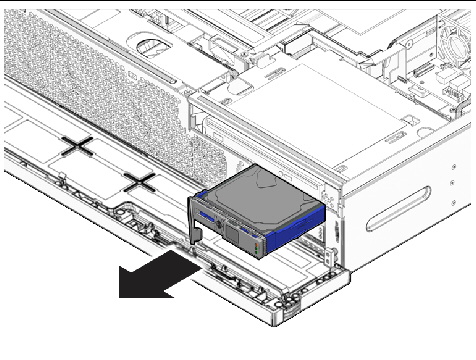
5. Grasp the latch and pull the drive out of the drive slot (FIGURE 3-5).
FIGURE 3-5 Removing Hard Drive
1. Remove the replacement hard drive from its packaging and place it on an antistatic mat.
2. Align the replacement drive to the drive slot.
The hard drive is physically addressed according to the slot in which it is installed. It is important to install a replacement drive in the same slot as the drive that was removed.
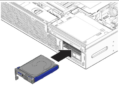
3. Slide the drive into the bay until it is fully seated (FIGURE 3-6).
FIGURE 3-6 Installing the Hard Drive
4. Close the latch to lock the drive in place.
6. Perform administrative tasks to reconfigure the hard drive.
The procedures that you perform at this point depend on how your data is configured. You might need to partition the drive, create file systems, load data from backups, or have it updated from a RAID configuration.
1. Prepare the server for media bay assembly removal. See:
3. Push the release tab to the left and pull the probe forward, freeing the optical media drive (FIGURE 3-7).
| Note - You do not need to remove the top cover to remove the optical media drive. The following illustration shows the top cover removed for clarity of placement. |
FIGURE 3-7 Releasing the Optical Media Drive
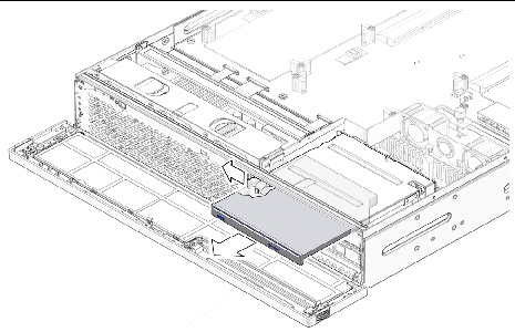
4. Remove the optical media drive from the media bay assembly and set it aside on an antistatic mat.
1. Remove the replacement optical media drive from its packaging and place it on an antistatic mat.
2. Hold the tab to the left and insert the optical media drive into the media bay assembly (FIGURE 3-8).
| Note - You do not need to install the top cover to remove the optical media drive. The following illustration shows the top cover removed for clarity of placement. |
FIGURE 3-8 Inserting the Optical Media Drive
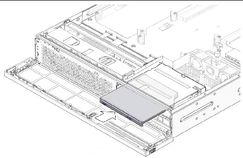
3. Press the optical media drive in until it seats and release the tab.
1. Prepare the server for media bay assembly removal. See:
2. Remove the optical media drive and the hard drives. See:
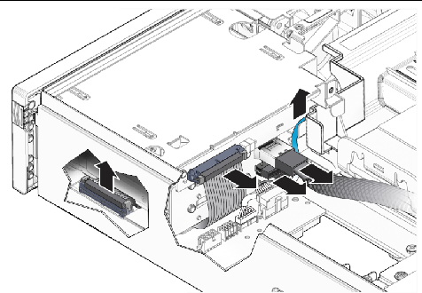
3. Disconnect the following cables from the media bay assembly (FIGURE 3-9):
a. (Optional) Disconnect the blue system fan tray assembly cable that connects to the PDB underneath the media bay assembly cables (FIGURE 3-9).
This step allows easier access to the media bay assembly cables.
b. Disconnect media bay assembly cable (top) that connects to the motherboard (FIGURE 3-9).
c. Disconnect media bay assembly cable (bottom) that connects to power distribution board (PDB) (FIGURE 3-9).
d. Disonnect media bay assembly ribbon cable that connects to the PDB (FIGURE 3-9).
You can disconnect this cable from the rear of the media bay assembly or from the PDB after loosening the screws and lifting the assembly out of the chassis.
FIGURE 3-9 Media Bay Assembly Cables
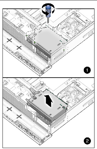
4. Loosen captive screws labeled 2 and 3, and remove non-captive screw labeled 1 closest to the front of the server (FIGURE 3-10).
5. Lift the media bay assembly out of the chassis (FIGURE 3-10).
FIGURE 3-10 Loosening the Media Bay Assembly Screws and Lifting From Chassis
6. (Optional) Disconnect and remove the ribbon cable from the PDB.
7. Set the media bay assembly aside on an antistatic mat.
1. Remove the replacement media bay assembly from its packaging and place it on an antistatic mat.
2. Move the cables as far out of the way as possible.
3. If disconnected, reconnect the media bay assembly ribbon cable to the PDB.
Arrange the cable where it can be reconnected to the assembly after it is reseated.
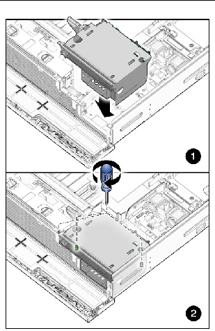
4. Lower the media bay assembly into the chassis until it seats (FIGURE 3-11).
5. Tighten the media bay assembly screws (FIGURE 3-11).
FIGURE 3-11 Setting the Media Bay Assembly Into Place and Tightening Screws
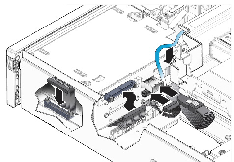
6. Connect the following cables to the media bay assembly (FIGURE 3-12):
FIGURE 3-12 Connecting the Media Bay Assembly Cables
7. Install the optical media drive and the hard drives. See:

Copyright © 2014, Oracle and/or its affiliates. All rights reserved.