| Sun Netra T5220 Server |
| Sun Netra T5220 Server |
| C H A P T E R 4 |
 Replacing Motherboard Assembly Components
 |
This chapter describes how to remove components from the motherboard assembly and how to remove the motherboard assembly itself. Topics include:
To prepare the server for servicing parts in this chapter, power off the server by performing the following procedures:
To bring the server back online, perform the following procedures:
The PCI mezzanine secures the PCIe cards into place with green PCI card retainers and captive (nonremovable) screws. The following figure shows the four PCI card retainers that ship with the server.

The following figure shows examples of how to use these retainers with differently sized PCI cards.
| Note - The short, straight retainers and the short, curved retainers can be used interchangeably to secure the same cards. The short, curved retainer provides more support. |
FIGURE 4-2 PCI Card Retainer Examples

|
Half-length, standard-height card secured with two short retainers |
|
|
Full-length, standard-height card secured with two short retainers and the retainer on the air duct |
| Note - The maximum power of any one PCI card is 25 watts. Only PCI-X slot 4 and PCIe slot 5 accept long cards. |
1. Prepare the server for PCI card removal. See Powering Off and Powering On the Server.
2. With the PCI mezzanine installed and cabled, identify which card is to be removed.
3. Loosen the appropriate PCI card retainers and securing screws (FIGURE 4-3).
The screws are captive and cannot be completely removed from the PCI mezzanine.
FIGURE 4-3 Upper PCI Card Retainers and Securing Screws

4. Slide the card to the left and lift it out of the PCI mezzanine (FIGURE 4-4).
FIGURE 4-4 Removing PCI-X 4 and PCIe 5 Cards From the PCI Mezzanine

Set the card aside on an antistatic mat.
6. Tighten the card securing screws.
7. Bring the server back online. See Powering Off and Powering On the Server.
1. Prepare the server for PCI card installation. See Powering Off and Powering On the Server.
2. With the PCI mezzanine installed and cabled, determine which slot to install the card and loosen the appropriate card securing screws (FIGURE 4-3).
3. Remove the replacement card from its packaging and place it onto an antistatic mat.
4. If a filler panel is installed, remove it by pulling the tab.
5. Lower the card into position on the PCI mezzanine, then slide it to the right to seat it into the connector (FIGURE 4-5).
You must secure the right side of the PCI card faceplate into the small slot on the right side of the PCI card slot (facing the rear of the server) before installing the PCI card.
FIGURE 4-5 Installing PCI-X 4 and PCIe 5 Cards in the PCI Mezzanine

6. Tighten the card securing screws and appropriate PCI retainers (FIGURE 4-3).
7. Bring the server back online. See Powering Off and Powering On the Server.
| Note - The maximum power of any one PCI card is 25 watts. Only PCI-X slot 4 and PCIe slot 5 accept long cards. |
1. Prepare the server for PCI card removal. See Powering Off and Powering On the Server.
2. With the PCI mezzanine installed and cabled, identify which card is to be removed.
3. Loosen the appropriate PCI card retainers and securing screws (FIGURE 4-3).
The screws are captive and cannot be completely removed from the PCI mezzanine.
4. Slide the card to the left and lift it out of the PCI mezzanine (FIGURE 4-4).
FIGURE 4-6 Removing the PCI-X 3 Card From the PCI Mezzanine

Set the card aside on an antistatic mat.
6. Tighten the card securing screws.
7. Bring the server back online. See Powering Off and Powering On the Server.
1. Prepare the server for PCI card installation. See Powering Off and Powering On the Server.
2. With the PCI mezzanine installed and cabled, loosen the appropriate card securing screws (FIGURE 4-3).
3. Remove the replacement card from its packaging and place it onto an antistatic mat.
4. If a filler panel is installed, remove it by pulling the tab (FIGURE 4-7).
5. Lower the card into position on the PCI mezzanine, then slide it to the right to seat it into the connector (FIGURE 4-7).
6. Tighten the appropriate card securing screws and PCI retainers (FIGURE 4-7).
FIGURE 4-7 Installing the PCI-X 3 Card in the PCI Mezzanine

7. Bring the server back online. See Powering Off and Powering On the Server.
| Note - The maximum power of any one PCI card is 25 watts. PCIe/XAUI slots 0 and 1 are the only slots that support XAUI cards. |
1. Prepare the server for card removal. See Powering Off and Powering On the Server.
2. Remove the PCI mezzanine and place it on an anti-static mat.
3. Loosen the appropriate card securing screws (FIGURE 4-8).
4. Lift the PCI riser assembly (with PCI card attached) from the PCI mezzanine (FIGURE 4-8).
5. If installed, remove the card securing screw on the right side of the PCI card faceplate (FIGURE 4-8).
6. Remove the PCI card from the PCI riser assembly (FIGURE 4-8).
FIGURE 4-8 Removing Lower PCIe/XAUI Cards From the PCI Mezzanine

7. Set the card aside on an antistatic mat.
9. Bring the server back online. See Powering Off and Powering On the Server.
1. Prepare the server for PCI card installation. See Powering Off and Powering On the Server.
2. Remove the PCI mezzanine and place it on an anti-static mat.
3. Remove the replacement card from its packaging and place it onto an antistatic mat.
4. Loosen the appropriate PCI riser assembly securing screws (FIGURE 4-9).
5. Lift the PCI riser assembly from the PCI mezzanine and place it on an antistatic mat.
6. If a filler panel is installed, remove it by pulling the tab (FIGURE 4-9).

|
Caution - Verify the PCI card you are installing matches the slot. The PCIe 0 and 1 slots are different than the PCIe 2 slot (FIGURE 4-10). The Sun Storage 6 Gb SAS PCIe RAID HBA, Internal card must be installed in PCIe slot 0 only. |
7. Slide the PCI card into the PCI riser assembly connector until fully seated.
8. Install the card securing screw on the right side of the PCI card faceplate (FIGURE 4-9).
9. Seat the PCI riser assembly into the PCI mezzanine (FIGURE 4-9).
10. Tighten the appropriate PCI riser assembly securing screws (FIGURE 4-9).
| Note - If you are installing the Sun Storage 6 Gb SAS PCIe RAID HBA, Internal (slot 0 only), see Cabling the Sun Storage 6 Gb SAS PCIe RAID HBA, Internal for important cabling instructions. |
FIGURE 4-9 Installing Lower PCIe/XAUI Cards in the PCI Mezzanine

11. Bring the server back online. See Powering Off and Powering On the Server.
12. See Chapter 6 to return the server to operation.
Refer to the Sun Storage 6 Gb SAS PCIe RAID HBA, Internal Installation Guide (E22410) for additional details.
This HBA requires a separate SAS cable (530-4088-01) that ships with the card, or can be ordered separately.
|
1. Remove the existing SAS cable connected to the SAS BackPlane (BP) connector and the motherboard near slot 0.
2. Install the card in PCIe slot 0, see Installing the Lower PCIe/XAUI Cards.
3. Connect the SAS cable (530-4088-01) to port SAS0 on the card and the SAS BP connector.
Route the SAS cable as shown in the following figure.
FIGURE 4-10 Cable Connections for the Sun Storage 6 Gb PCIe SAS RAID HBA

|
Unulug existing SAS cable from the SAS BackPlane (BP) connector and from the motherboard near slot 0 |
|
|
Plug the new SAS cable into port SAS0 of the HBA and into the SAS BP connector. |
4. Bring the server back online. See Powering Off and Powering On the Server.
5. See Chapter 6 to return the server to operation.
1. Prepare the server for air duct removal. See Powering Off and Powering On the Server.
2. Facing the server, release the tab on the right of the air duct and pull upward (FIGURE 4-11).
3. Lift the duct out of the chassis, releasing it from the pins on the left side of the chassis, and set it aside on an antistatic mat (FIGURE 4-11).
FIGURE 4-11 Removing the Air Duct

1. Remove the replacement air duct from its packaging.
2. With the duct at a 45 degree angle, position the pin holes in the duct to align with the pins of the chassis (FIGURE 4-12).
3. Lower the duct to the horizontal position until the tab secures in place (FIGURE 4-12).
FIGURE 4-12 Installing the Air Duct

5. See Chapter 6 to return the server to operation.
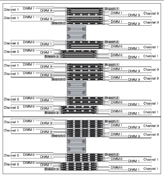
Use these FB-DIMM configuration rules, FIGURE 4-13, and TABLE 4-1 to help you plan the memory configuration of your server.
| Note - On each branch, populate CH0/D0 first. Populate CH1/D0 second. |
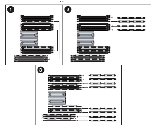
FIGURE 4-14 FB-DIMM Upgrade Path
|
FB-DIMM Installation Order[1] |
FB-DIMM Pair[2] |
||||
|---|---|---|---|---|---|
| Note - FB-DIMM names in ILOM messages are displayed with the full FRU name, such as /SYS/MB/CMP0/BR0/CH0/D0. |
This section describes how to diagnose and replace faulty FB-DIMMs. For FB-DIMM configuration guidelines, see FB-DIMM Layout.

|
Caution - Ensure that all power is removed from the server before removing or installing FB-DIMMs. You must disconnect the power cables before performing this procedure. |
|
|
Caution - Always perform antistatic measures by using a wrist strap and an antistatic mat for handling and storing removable components. |
| Note - To remove and install some of the FB-DIMMs, you might need to remove and reinstall the media bay assembly and cables. If this is necessary, see Replacing the Media Bay Assembly. |
The system Service Required LED lights if the system detects a FB-DIMM fault.
Use the showfaults command to identify faulty FB-DIMMs. See Displaying System Faults.
Use the FB-DIMM fault locator button on the motherboard to identify faulty FB-DIMMs.
1. Prepare the server for FB-DIMM removal. See Powering Off and Powering On the Server.
2. Remove the FB-DIMM/CPU duct.
3. Press the FB-DIMM fault locator button on the motherboard.
The button is located on the left edge of the motherboard, next to /SYS/MB/CMP0/BR3/CH1/D1 (J1701).
4. Note the location of faulty FB-DIMMs.
Faulty FB-DIMMs are identified with a corresponding amber LED on the motherboard.
| Note - The FB-DIMM fault LEDs remain lit only for a few minutes. |
5. Ensure that all FB-DIMMs are seated correctly in their slots.
1. Prepare the server for FB-DIMM removal. See Powering Off and Powering On the Server.
2. Remove the FB-DIMM/CPU duct.
3. If you are replacing a faulty FB-DIMM, locate the FB-DIMMs that you want to replace.
Press the DBDIMM DIAG button on the motherboard to activate the DB-DIMM status LEDs. Any faulty FB-DIMMs will be indicated with a corresponding amber fault LED on the motherboard.
| Tip - Make a note of the faulty FB-DIMM location so that you can install the replacement FB-DIMM in the same location. |
| Note - For memory configuration information see FB-DIMM Layout. |
4. Push down on the ejector tabs on each side of the FB-DIMM until the FB-DIMM is released (FIGURE 4-15).
5. Grasp the top corners of the faulty FB-DIMM and remove it from the server.

6. Place the FB-DIMM on an antistatic mat.
7. Repeat Step 4 through Step 6 to remove any additional FB-DIMMs.
1. Unpackage the replacement FB-DIMMs and place them on an antistatic mat.
| Tip - See FB-DIMM Layout for information about configuring the FB-DIMMs. |
2. Ensure that the ejector tabs are in the open position.
3. Line up the replacement FB-DIMM with the connector (FIGURE 4-16).
Align the FB-DIMM notch with the key in the connector. This ensures that the FB-DIMM is oriented correctly.
4. Push the FB-DIMM into the connector until the ejector tabs lock the FB-DIMM in place.
If the FB-DIMM does not easily seat into the connector, verify that the orientation of the FB-DIMM is as shown in FIGURE 4-16. If the orientation is reversed, damage to the FB-DIMM might occur.
FIGURE 4-16 Inserting the FB-DIMM Into the Slot

5. Repeat Step 2 through Step 4 until all replacement FB-DIMMs are installed.
b. Bring the server back online. See Powering Off and Powering On the Server
1. Access the ALOM CMT sc> prompt.
Refer to the Sun Integrated Lights Out Management 2.0 Supplement for the Sun Netra T5220 Server for instructions.
2. Run the showfaults -v command to determine how to clear the fault.
The method you use to clear a fault depends on how the fault is identified by the showfaults command.
In most cases, the replacement of the faulty FB-DIMM(s) is detected when the service processor is power cycled. In this case, the fault is automatically cleared from the system. If the fauilt is still displayed by the showfaults command, then run the enablecomponent command to enable the FB-DIMM and clear the fault.
3. Perform the following steps to verify the repair:
a. Set the virtual keyswitch to diag so that POST will run in Service mode.
c. Switch to the system console to view POST output.
Watch the POST output for possible fault messages. The following output is a sign that POST did not detect any faults:
. . . 0:0:0>INFO: 0:0:0> POST Passed all devices. 0:0:0>POST: Return to VBSC. 0:0:0>Master set ACK for vbsc runpost command and spin... |
d. Return the virtual keyswitch to normal mode.
e. Issue the Solaris OS fmadm faulty command.
No memory faults should be displayed.
If faults are reported, refer to the diagnostics flowchart in FIGURE 1-1 for an approach to diagnose the fault.
4. Gain access to the ALOM CMT sc> prompt.
5. Run the showfaults command.
6. Run the clearfault command.
7. Switch to the system console.
8. Issue the fmadm repair command with the UUID.
Use the same UUID that you used with the clearfault command.
1. Prepare the server for battery removal. See Powering Off and Powering On the Server.
2. Pry the battery out of the service processor board using a small flat-blade screwdriver (FIGURE 4-17).
FIGURE 4-17 Prying the Battery From the Motherboard

3. Set the battery aside on an antistatic mat.
4. Continue to Installing the Battery.
| Note - The Sun Netra T5220 server uses one of three lithium CR2032 batteries (part number 371-2210-01: Panasonic, Maxell or Renata). |
1. Remove the replacement battery from its packaging.
2. Press the new battery in with the “+” side facing up (FIGURE 4-18).
FIGURE 4-18 Inserting the Battery Into the Service Processor Board

3. Bring the server back online. See Powering Off and Powering On the Server.
4. See Chapter 6 to return the server to operation.
1. Prepare the server for NVRAM removal. See Powering Off and Powering On the Server.
2. Carefully pull the NVRAM from the service processor board (FIGURE 4-19).
FIGURE 4-19 Pulling the NVRAM From the Service Processor Board

3. Set the NVRAM aside on an antistatic mat.
1. Remove the replacement NVRAM from its packaging and place it on an antistatic mat.
2. Align the notch in the NVRAM socket with the key on the underside of the NVRAM, and press it into place (FIGURE 4-20).
FIGURE 4-20 Pressing the NVRAM Into the Socket

4. See Chapter 6 to return the server to operation.
| Note - The SCC module is also known as the IDPROM chip. |
1. Prepare the server for SCC module removal.
See Powering Off and Powering On the Server.
See Removing the PCI Mezzanine.
5. Carefully pull the SCC module straight up from its connector.
1. Align the SCC module with its connector on the motherboard.
| Note - The SCC module and its connector are keyed. |
2. Press the SCC module down until it seats.
See Installing the PCI Mezzanine.
5. Bring the server back online.
See Powering Off and Powering On the Server.
6. If the previous SCC module had modified ILOM configuration variables and you recorded them, configure the new SCC module with those values.
7. Return the server to operation.
See Chapter 6.
1. Back up OpenBoot PROM variables with one of the following procedures:
2. Prepare the server for motherboard assembly removal. See Powering Off and Powering On the Server.
3. Remove the following components:
4. Disconnect the cables connected to the motherboard (FIGURE 4-21).
a. Disconnect the cable connected to the PDB.
b. Disconnect the two cables connected to the media bay assembly.
FIGURE 4-21 Removing the Cables Connected to the Motherboard

5. Loosen or remove the screws that secure the motherboard assembly to the chassis (FIGURE 4-22).
FIGURE 4-22 Removing the Motherboard Assembly Screws

6. Loosen the two captive screws at the center of the motherboard assembly (FIGURE 4-22).
7. Lift slighty and slide the motherboard assembly forward approximately one inch (25.4 mm) (FIGURE 4-23).
8. Lift up on the right edge to approximately a 45 degree angle (FIGURE 4-23).
9. Remove the motherboard assembly from the chassis (FIGURE 4-23).
FIGURE 4-23 Removing the Motherboard Assembly From the Chassis

10. Set the motherboard assembly aside on an antistatic mat.
11. Continue to Installing the Motherboard Assembly.
1. Remove the replacement motherboard assembly from its packaging and place it on an antistatic mat.
2. Lower the left edge of the motherboard assembly into the chassis, then the entire board, and while slightly elevated, slide the motherboard assembly to the back of the chassis (FIGURE 4-24).
FIGURE 4-24 Installing the Motherboard Assembly Into the Chassis

3. Align the motherboard assembly screw holes over the chassis standoffs.
4. Tighten the two captive screws at the center of the motherboard assembly (FIGURE 4-25).
FIGURE 4-25 Installing the Motherboard Assembly Screws

5. Install the two power screws and four other screws that secure the motherboard assembly to the chassis (FIGURE 4-25).
6. Reconnect the cables to the following connectors on the motherboard assembly (FIGURE 4-26):
FIGURE 4-26 Reconnecting the Cables to the Motherboard Assembly

7. Install the following components:
8. Bring the server back online.
See Powering Off and Powering On the Server.
9. Restore OpenBoot PROM variables with one of the following procedures:
10. Return the server to operation.
See Chapter 6.
| Sun Netra T5220 Server | E21359-03 |
Copyright © 2014, Oracle and/or its affiliates. All rights reserved.
 To Remove the P