| C H A P T E R 3 |
|
Maintaining the Sun Fire X2270 Server |
This chapter describes how to add, replace, and configure components in the Sun Fire X2270 Server after it has been set up.
This chapter contains the following sections:
To determine and isolate a faulty component, refer to the Sun x64 Servers Diagnostics Guide, 820-6750.
You need the following tools and supplies for performing Sun Fire X2270 Server maintenance procedures.
Before removing the system’s top cover, read the following sections. These sections contain important electrostatic discharge (ESD) precautions, along with preinstallation and postinstallation instructions.
ESD can damage your processor, disk drives, expansion boards, and other components. Always observe the following precautions before you install a system component.
Always perform the following steps before you install any component:
1. Turn off the system and all of the peripherals connected to it.

|
Caution - Failure to properly turn off the system before you start installing components can cause serious component damage. |

|
Caution - Follow the ESD precautions described in ESD Precautionswhen handling a system component. |
See Powering Off the Server and Removing the Cover for the appropriate procedure for removing the cover from the server.
Perform the following steps after installing a server component.
1. Ensure that all of the components are installed as described in the component replacement instructions.
See Component Replacement Procedures.
2. Reinstall any PCI Express (PCIe) cards or peripherals that you had previously removed.
See Component Replacement Procedures.
3. Reinstall the system’s cover.
See Powering Off the Server and Removing the Cover.
4. Connect all external cables to the system.
See Powering On and Powering Off the Server.
For your safety, perform this procedure when you are powering off the system and removing the cover for a maintenance procedure in this chapter.
1. If the operating system (OS) is running, perform a shutdown of the OS, and then press and release the platform Power button on the front panel.
2. Turn off all peripheral devices connected to the system.
3. Disconnect the AC power on the back panel of the server (see FIGURE 1-3).
4. Label and disconnect all peripheral cables and all telecommunication lines connected to I/O connectors or ports on the back panel of the system.

|
Caution - The system’s printed circuit boards and hard disk drives contain components that are extremely sensitive to static electricity. |
5. Before handling components, attach a wrist strap to a chassis ground (any unpainted metal surface).
6. Loosen the captive screw securing the cover to the chassis (see FIGURE 3-1).
7. Pull the cover slightly toward the back of the server and then straight up to remove it.
8. Lift the cover and remove it.
FIGURE 3-1 Removing the Server Cover
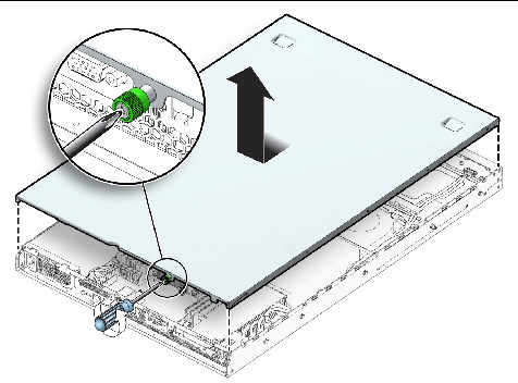
| Note - Perform the reverse of these procedures to reinstall the server cover. |
FIGURE 3-2 Sun Fire X2270 Server System Components
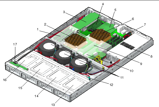
The following components are customer-replaceable units (CRUs):
The following components should be replaced only by trained field service technicians:
The following procedures describe how to remove and replace an I/O board.
1. Power off the server, including any attached peripherals, and disconnect the server from the electrical outlet.
Refer to Powering Off the Server and Removing the Cover.
2. Remove the screws securing the I/O board to the hard disk drive (HDD) cage.
FIGURE 3-3 Removing the I/O Board
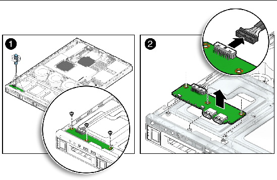
3. Lift the I/O board up slightly to clear the shoulder standoffs, then pull back to remove the I/O board from the system.
4. Remove the cable connected to the I/O board.
1. Position the I/O board on top of the HDD cage so the openings on the board line up with the guides on top of the HDD cage.
FIGURE 3-4 Installing the I/O Board
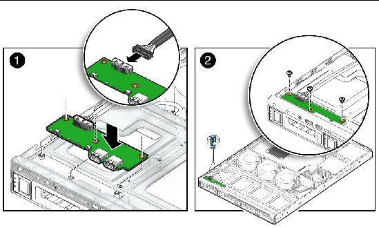
3. Gently push the I/O board forward, then down on to the shoulder standoffs to secure it.
4. Fasten the screws to secure the I/O board to the mounting bracket.
5. Check the routing of all cables for obstructions, and then reinstall the cover as described in Powering Off the Server and Removing the Cover.
The PCIe riser installed in the server is a low-profile, half-length x16 connector card, supporting up to 35W cards.
The following sections describe how to remove or install a PCIe riser.
1. Power off the system and remove the cover as described in Powering Off the Server and Removing the Cover.
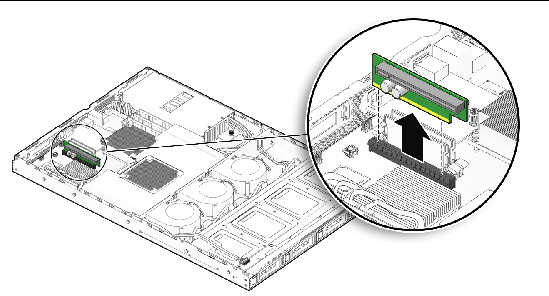
FIGURE 3-5 Removing the PCIe Riser
2. If a PCIe card is connected to the PCIe riser, remove the PCIe card as described in Removing the PCIe Card.
3. Using your fingers, pull the PCIe riser upward to disengage the riser card from the connector on the motherboard.
4. If you are not replacing the PCIe riser, check the routing of all cables for obstructions, and then reinstall the cover as described in Powering Off the Server and Removing the Cover.
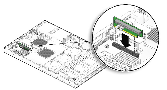
1. Using your fingers, gently push down on the PCIe riser to engage the card to the connector on the motherboard. See FIGURE 3-6.
FIGURE 3-6 Installing the PCIe Riser
2. If you are installing a PCIe card, install the card as described in Installing the PCIe Card.
3. Check the routing of all cables for obstructions, and then reinstall the cover as described in Powering Off the Server and Removing the Cover.
The following sections describe how to remove or install a PCIe card.
1. Power off the system and remove the cover as described in Powering Off the Server and Removing the Cover.
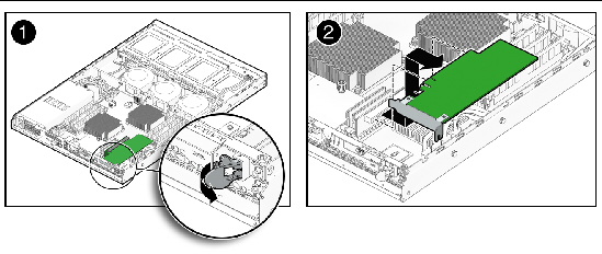
2. Unlatch the PCIe card and slide the card from PCIe slot in the back panel of the server chassis, then disengage the PCIe card from the connector on the riser card.
See FIGURE 3-7.
FIGURE 3-7 Removing a PCIe Card
3. If you are replacing a PCIe card, install the card as described in Installing the PCIe Card; if you are not replacing the PCIe card, install a filler panel in the back panel of the server chassis.
4. Check the routing of all cables for obstructions, and then reinstall the cover as described in Powering Off the Server and Removing the Cover.
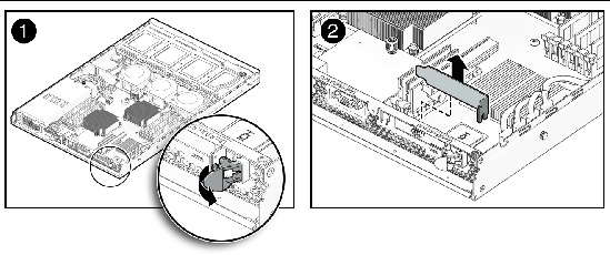
1. If necessary, remove the filler panel from the back panel of the server chassis.
See FIGURE 3-8.
FIGURE 3-8 Removing the PCIe Filler Panel
2. If a PCIe riser is not already installed in the server, install a PCIe riser as described in Installing the PCIe Riser.
3. Slide the new PCIe card into the PCIe slot on the back panel of the server chassis and engage the PCIe card to the connector on the PCIe riser.
See FIGURE 3-9.
FIGURE 3-9 Installing the PCIe Card
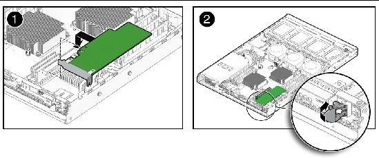
4. Fasten the latch to secure the card.
5. Check the routing of all cables for obstructions, and then reinstall the cover as described in Powering Off the Server and Removing the Cover.
The following procedures describe how to remove and replace a removable disk drive and carrier. Use these procedures if your server contains optional removable SATA hard disk drives (HDDs) or solid state drives (SSDs).
If your server contains a filler panel, you must remove the filler panel before installing a disk drive.
1. On the drive you want to install, rotate the lever to disengage the hook, then pull the filler panel from the server.
FIGURE 3-10 Removing a Removable Disk Drive Filler Panel
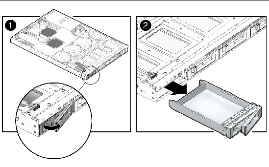
2. Continue with the instructions for installing a removable disk drive and carrier as described in Installing a Removable Disk Drive and Carrier.
To remove the removable disk drive and carrier:
1. If you are not using an integrated-mirroring (IM) configuration, you must power off the server before removing a disk drive; it is not necessary to remove the cover. Power off the system as described in Powering Off the Server and Removing the Cover.
If you are using an IM configuration, start with Step 2.
2. On the drive you want to remove, push the release button to open the latch.
FIGURE 3-11 Removing a Removable Disk Drive
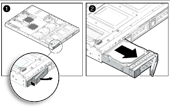
3. Grasp the latch and pull the drive out of the drive slot.
| Note - The latch is not an ejector. Do not bend it too far to the right. Doing so may damage the latch. |
4. Reinsert the disk drive and carrier into the server as described in Installing a Removable Disk Drive and Carrier.
| Note - If you are installing a new disk drive, rather than replacing an already installed drive, you will need to remove the filler panel from the drive cage before installing the new disk drive. See Removing a Filler Panel. |
To install the removable disk drive and carrier:
1. Slide the drive into the drive slot until it is fully seated.
FIGURE 3-12 Installing a Removable Disk Drive
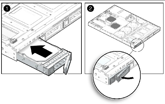
2. Close the latch to lock the drive in place.
The following procedure describes how to replace the disk drive backplane assembly. The disk drive backplane is used in server configurations that contain optional removable SATA HDDs or SSDs.
To remove the disk drive backplane:
1. Remove all disk drives as described in Removing a Removable Disk Drive and Carrier.
This ensures that HDD/SSDs are detached from the backplane assembly.
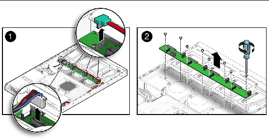
2. Disconnect the HDD/SSD power cable (1) and SATA cables (4) from the backplane assembly.
3. Remove the screws (8) fastening the backplane assembly to the server chassis.
4. Carefully lift the backplane assembly from the server chassis.
FIGURE 3-13 Removing the Disk Drive Backplane Assembly
To install the disk drive backplane assembly:
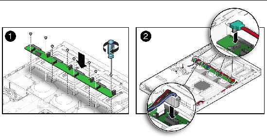
1. Reinsert the backplane assembly into the server chassis.
2. Fasten the screws (8) to secure the backplane assembly to the server chassis.
3. Reinstall the HDD/SSD power (1) and SATA cables (4) to the backplane assembly.
FIGURE 3-14 Replacing the Disk Drive Backplane Assembly
4. Reinsert all HDD/SSDs as described in Installing a Removable Disk Drive and Carrier.
5. Check the routing of all cables for obstructions, and then reinstall the cover as described in Powering Off the Server and Removing the Cover.
The following procedures describe how to remove and replace a fixed hard disk drive and carrier. Use these procedures if your server contains optional fixed SATA hard disk drives (HDDs) or solid state drives (SSDs).
If your server contains a filler panel, you must remove the filler panel before installing a fixed disk drive.
1. Power off the system as described in Powering Off the Server and Removing the Cover.
2. On the drive you want to install, remove the screws (2) that attach the filler panel to the back of the carrier.
FIGURE 3-15 Removing a Fixed Disk Drive Filler Panel
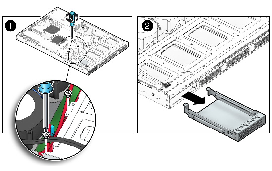
3. Carefully slide the filler panel forward and out of the server.
4. Continue with the instructions for installing a fixed disk drive and carrier as described in Installing a Fixed Disk Drive and Carrier.
To remove the fixed disk drive and carrier:
1. Power off the system as described in Powering Off the Server and Removing the Cover.
2. Disconnect the SATA cable from the disk drive.
3. Disconnect the power harness.
4. Remove the screws (2) that attach the disk drive to the back of the carrier.
FIGURE 3-16 Removing a Fixed Disk Drive and Carrier
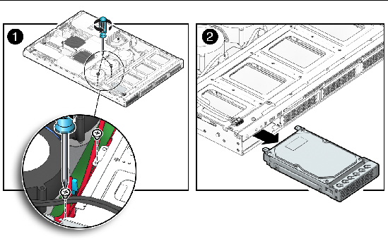
5. Carefully slide the drive forward and out of the server, pushing the unit out using the legs.
6. Reinsert the carrier into the server as described in Installing a Fixed Disk Drive and Carrier.
| Note - If you are installing a new fixed disk drive, rather than replacing an already installed drive, you will need to remove the empty filler panel from the drive cage before installing the new drive. See Removing a Filler Panel. |
To install the fixed disk drive and carrier:
1. Power off the system as described in Powering Off the Server and Removing the Cover.
2. Remove the screws (2) from the back of the carrier and push it out of the front of the server.
FIGURE 3-17 Installing a Fixed Disk Drive and Carrier

3. Grasping the body of the drive in both hands, carefully insert the connector end of the drive into the front of the server, sliding it into the server until it reaches the back of the drive bay.
4. Fasten the screws (2) that attach the disk drive to the back of the carrier.
5. Reattach the SATA cable to the disk drive.
7. Check the routing of all cables for obstructions, and then reinstall the cover as described in Powering Off the Server and Removing the Cover.
8. Reapply power to the server as described in Powering On and Powering Off the Server and test the drive to determine if it is working correctly.
The following procedures describe how to replace the system air duct.
1. Power off the system and remove the cover as described in Powering Off the Server and Removing the Cover.
2. Pull the air duct up and out of the chassis.
FIGURE 3-18 Removing the Air Duct
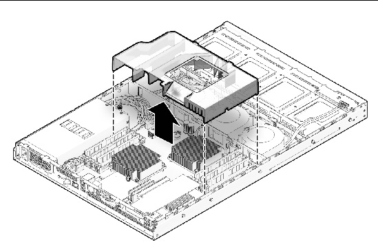
 Position the air duct into the chassis as shown in FIGURE 3-19, aligning the baffle with the indents and opening in the chassis divider.
FIGURE 3-19 Installing the Air Duct
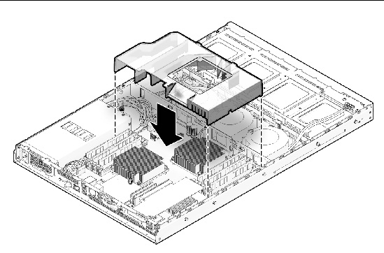
The following procedures describe how to replace the power supply. Your chassis may contain either a 400 watt or 600 watt power supply. The removal and installation procedures are the same for both power supplies.
1. Power off the system and remove the cover as described in Powering Off the Server and Removing the Cover.
2. Disconnect the three power supply cables from the motherboard.
3. Disconnect the power supply from the disk drives.
FIGURE 3-20 Removing the Power Supply
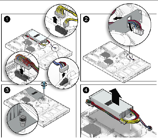
5. Lift the power supply out of the chassis.
1. Position the power supply over the chassis power-supply cage.
2. Insert the power supply into the chassis and push it forward so that it is flush with the back panel.
3. Install the power supply and fasten the captive screw.
FIGURE 3-21 Installing the Power Supply
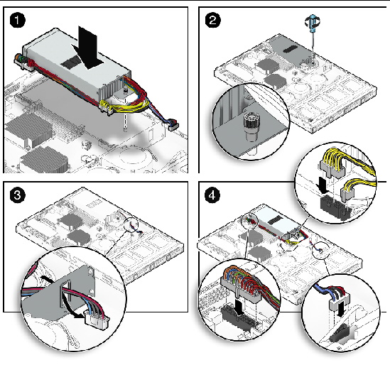
4. Connect three of the power supply cables to the motherboard. See FIGURE 3-41.
5. Reconnect the power supply to the disk drives.
6. Check the routing of all cables for obstructions, and then reinstall the cover.
The following procedures describe how to replace a blower module. The X2270 server contains three blower modules.
1. Power off the system and remove the cover as described in Powering Off the Server and Removing the Cover.
2. Remove the air duct as described in Replacing the Air Duct.
3. Unplug the fan’s power connector from the motherboard.
FIGURE 3-22 Removing a Blower Module
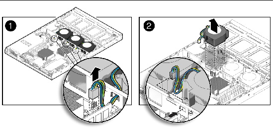
4. Pull the fan module upward while pushing the connector cable through the cutout in the chassis divider, taking care not to catch the connector on the metal, to remove it from the chassis.
1. Position the blower module so that it fits over the guideposts and the duct opening fits into the cutouts in the chassis divider.
FIGURE 3-23 Installing a Blower Module
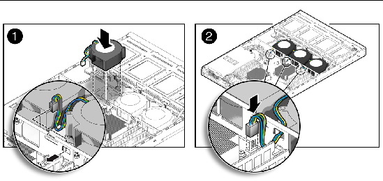
2. Gently push the blower module down while directing the connector cable through the cutout in the chassis divider, until it is seated on the guideposts.
| Note - Ensure that the connector cable has been directed through the connector opening in the chassis divider and not through the blower exhaust opening. |
3. Connect the blower connector to the appropriate connector on the motherboard.
4. Check the routing of all cables for obstructions, and then reinstall the air duct and system cover.
The Sun Fire X2270 Server supports a variety of DIMM configurations that can include dual-rank (DR) or single-rank (SR) DIMMs. When replacing or upgrading a DIMM on the server you should consider the following:
For details, see FIGURE 3-24 and FIGURE 3-25.
For details, see DIMM Population Rules.
For details, see Removing a DIMM and Installing a DIMM.
For details, see Error Correction and Parity.
| Note - Keep in mind the following information and rules when you use the procedures in this section to replace or add DIMMs to the server. |
1. Power off the system and remove the cover as described in Powering Off the Server and Removing the Cover.
2. Remove the air duct as described in Replacing the Air Duct.
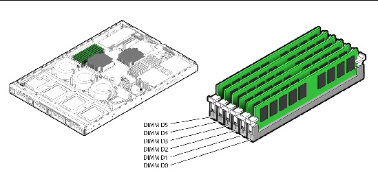
3. Locate the DIMM connector in which you will install or replace a memory module.
Bank 0 is the bank closest to CPU 0 and Bank 1 is the bank closest to CPU 1. See FIGURE 3-24 and FIGURE 3-25.
FIGURE 3-24 Bank 0 DIMM Slot Locations
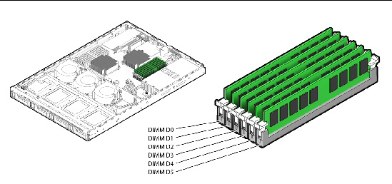
FIGURE 3-25 Bank 1 DIMM Slot Locations
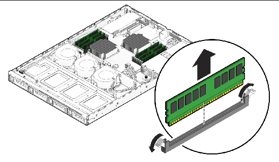
4. Remove a DIMM by pressing down on the ejector levers at both ends of the memory module’s socket (see FIGURE 3-26).
5. Pull the DIMM up and out of the socket.
1. Refer to DIMM Population Rules before installing DIMMs.
2. Ensure that the DIMM socket ejector levers are open (rotated outward) to allow the new module to be inserted.
3. Align the DIMM’s edge connector with the alignment key and insert the memory module into the connector.
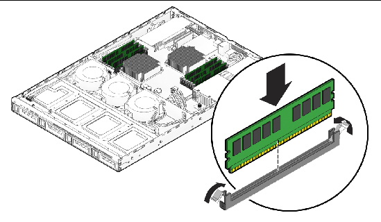
4. Using both thumbs, press the DIMM straight down into the DIMM slot until both ejector levers click, locking the DIMM in the DIMM slot.
5. Check the routing of all cables for obstructions, then reinstall the air duct and the system cover.
The server’s processor provides parity protection on its internal cache memories and error-correcting code (ECC) protection of the data. The system can detect and log to the system event log the following types of errors:
Advanced ECC corrects up to 4 bits in error on nibble boundaries, as long as they are all in the same DRAM. If a DRAM fails, the DIMM continues to function.
Refer to the Sun Integrated Lights Out Manager 2.0 User’s Guide (820-1188) for information on how to access the error log.
The following procedure describes how to remove and install flash memory modules (F-MODs).
To remove a flash memory module:
1. Power off the system and remove the cover as described in Powering Off the Server and Removing the Cover.
2. Locate the F-MOD connector in which you will install or replace a memory module.
FIGURE 3-28 Flash Memory Module Slot Locations
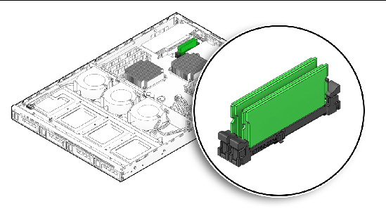
3. Remove an F-MOD by pressing down on the ejector levers at both ends of the memory module’s socket (see FIGURE 3-29).
4. Pull the F-MOD up and out of the socket.
FIGURE 3-29 Removing a Flash Memory Module
To install a flash memory module:
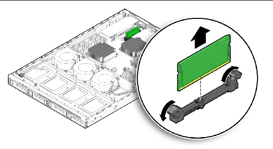
1. Ensure that the F-MOD socket ejector levers are open (rotated outward) to allow the new memory module to be inserted.
2. Align the F-MOD’s edge connector with the alignment key and insert the memory module into the connector.
FIGURE 3-30 Installing a Flash Memory Module
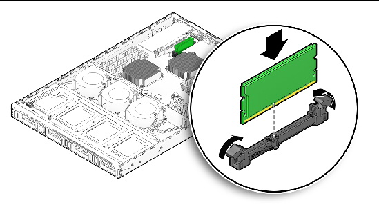
3. Using both thumbs, press the F-MOD straight down into the slot until both ejector levers click, locking the F-MOD into the slot.
4. Check the routing of all cables for obstructions, and then reinstall the cover.
The system battery is a common CR2032 calculator battery.
You might need to replace the system battery if you know it is weak or if after any period of AC power loss, the BIOS loses its CMOS settings, or if the time-of-day clock loses time.

|
Caution - Do not attempt to open or service batteries. The battery contains lithium and can explode if not properly used, handled, or disposed of. |
1. Power off the system and remove the cover as described in Powering Off the Server and Removing the Cover.
2. Remove the air duct as described in Removing the Air Duct.
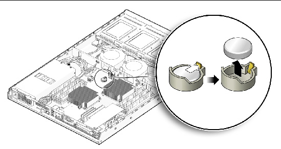
3. Remove the system battery by gently pulling the clip away from the side of the battery and sliding the battery out of the battery holder (see FIGURE 3-31 for the location).
FIGURE 3-31 Removing the System Battery
To install the system battery:
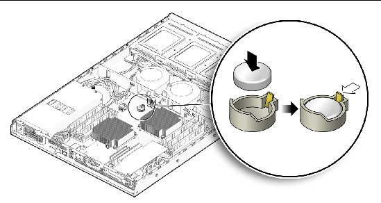
1. Insert the new system battery into the battery holder with the side labeled “+” facing upward.
FIGURE 3-32 Installing the System Battery
| Note - Replace the battery only with the identical model. |
2. Reinstall the air duct as described in Installing the Air Duct.
3. Check the routing of all cables for obstructions and then reinstall the cover.
The following procedures describe how to remove and replace the service processor (SP) module.
1. Power off the server, including any attached peripherals, and disconnect the server from the electrical outlet.
Refer to Powering Off the Server and Removing the Cover.
2. Remove any Ethernet or video cables that are attached to the rear of the SP module. See FIGURE 1-3 for the location of the connectors.
3. Remove the screw securing the SP module to the server motherboard.
FIGURE 3-33 Removing the SP Module
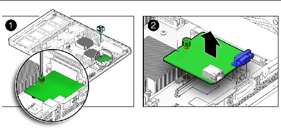
4. Pull the SP module upward to disengage the card from the SP motherboard connector and SP alignment pin, slide the board slightly forward to clear the rear wall of the server chassis, then lift the SP module from the chassis.
| Note - If you are installing the SP module for the first time, you should install the SP module alignment pin before installing the SP module. The SP module alignment pin is designed to help align the SP module with the card connector. Install the SP module alignment pin by sliding the alignment pin down over the screw post. (See FIGURE 3-34.) The SP module alignment pin is shipped with the SP module. |
1. Position the SP module so that the card’s RJ-45 and HD15 connectors slide into the back panel of the server chassis and the card connector is aligned with the SP motherboard connector.
FIGURE 3-34 Installing the SP Module
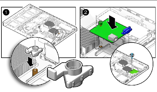
2. Gently push the SP module down to engage the card connector to the SP motherboard connector and the SP alignment pin.
3. Fasten the screw to secure the SP module to the server motherboard.
4. Reattach any Ethernet or video cables to the rear of the SP module.
See FIGURE 1-3 for the location of the connectors.
5. Check the routing of all cables for obstructions, and then reinstall the cover as described in Powering Off the Server and Removing the Cover.
The following procedure describes how to replace a CPU. The Sun Fire X2270 Server supports both single-CPU and dual-CPU configurations.
| Note - Replacement of a CPU and heatsink should only be done by trained service personnel. If you are adding a second CPU to a single CPU configuration, see Installing a New CPU. |

|
Caution - Observe the appropriate ESD precautions in ESD Precautionswhen handling the CPU. |
1. Power off the system and remove the cover as described in Powering Off the Server and Removing the Cover.
2. Remove the air duct as described in Replacing the Air Duct.
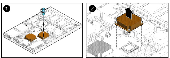
3. Remove the four screws securing the heatsink to the board (see FIGURE 3-35).
FIGURE 3-35 Removing a Heatsink

|
Caution - The heatsink can become extremely hot. Be sure it has had sufficient time to cool before handling. |
4. Twist the heatsink slightly to the right or left to break the seal with the thermal grease.
5. Lift the heatsink away from the CPU.
6. Place the heatsink upside-down on a flat surface to prevent the thermal grease from contaminating other components.
7. Pull the socket release lever up to the fully open, perpendicular position.
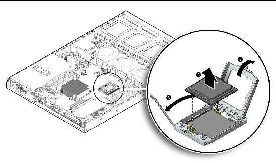
9. Lift the CPU out of the socket, leaving the release lever in the open position.
| Note - Ensure that no thermal grease that might be left from the heatsink comes into contact with the CPU socket or underside of the CPU chip. |
Follow these steps to install a CPU and heatsink if you are replacing a CPU. If you want to install a new CPU or install a second CPU into a formerly single-CPU system, see Installing a New CPU.

|
Caution - Observe the appropriate ESD precautions in ESD Precautionswhen handling the CPU. |
2. Ensure that the socket release lever is in the fully open, perpendicular position and the CPU cover is open (see FIGURE 3-37).
3. Align the small triangle on the upper-left corner of the CPU with the alignment triangle on the motherboard. In addition, ensure that the alignment post on the socket engages the semi-circular cutout on the CPU.
FIGURE 3-37 Installing the CPU
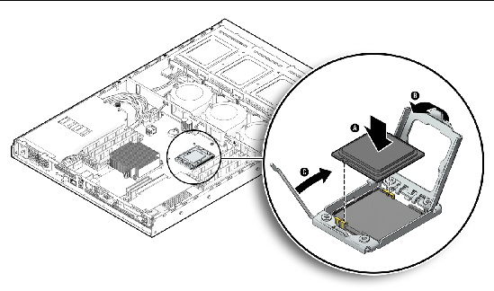
4. Insert the CPU into the socket.
5. When the CPU is fully seated in the socket, close the CPU cover.
6. Rotate the socket release lever down until it snaps into place, securing the CPU in the socket.
7. Use the entire syringe contents to apply thermal grease in a star pattern to the top of the CPU.
| Note - If you are replacing an existing heatsink with a new heatsink, you do not need to use the syringe to add additional thermal grease to the heatsink, as new heatsinks are pre-greased. |
8. Gently distribute the thermal grease and remove any excess so that only an extremely thin, uniform layer remains. If any voids or crevices appear that could lead to air pockets, reapply the grease until you achieve a thin but compact consistency.
9. Use an alcohol pad to remove all thermal grease from the bottom of the previously used heatsink.
10. Inspect the heatsink for dust and lint. Clean if necessary.
11. Carefully position the heatsink on the CPU, aligning it with the mounting posts to reduce movement after it makes initial contact with the layer of thermal grease.

|
Caution - If the heatsink is moved too much during its installation, the layer of thermal grease may become uneven, leading to component damage. |
12. Fasten the four screws attaching the heatsink to the motherboard. Alternate between the four screws, turning each screw two turns until all are securely fastened. See FIGURE 3-38.
FIGURE 3-38 Installing the Heatsink
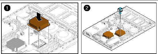
13. Reinstall the air duct and the system cover.
| Note - Replacement of a CPU and heatsink should only be done by trained service personnel. If you are replacing an already installed CPU, rather than adding a new one, follow the instructions in Replacing a CPU and Heatsink. |

|
Caution - Observe the appropriate ESD precautions in ESD Precautionswhen handling the CPU. |
To install a new CPU and heatsink:
2. If you are installing a second CPU into a formerly single-CPU system, you will need to remove the socket cover before installing the new CPU.
3. Ensure that the socket release lever is in the fully open, perpendicular position and the CPU cover is open (see FIGURE 3-37).
4. Align the small triangle on the upper-left corner of the CPU with the alignment triangle on the motherboard. In addition, ensure that the alignment post on the socket engages the semi-circular cutout on the CPU.
FIGURE 3-39 Installing the CPU
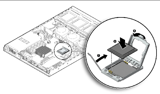
5. Insert the CPU into the socket.
6. When the CPU is fully seated in the socket, close the CPU cover.
7. Rotate the socket release lever down until it snaps into place, securing the CPU in the socket.
8. Inspect the heatsink for dust and lint. Clean if necessary.
9. Remove the plastic protective cover from the bottom of the heatsink.
The plastic cover protects the grease on the bottom of the heatsink.
10. Carefully position the heatsink on the CPU, aligning it with the mounting posts to reduce movement after it makes initial contact with the layer of thermal grease.

|
Caution - If the heatsink is moved too much during its installation, the layer of thermal grease may become uneven, leading to component damage. |
11. Fasten the four screws attaching the heatsink to the motherboard. Alternate between the four screws, turning each screw two turns until all are securely fastened. See FIGURE 3-40.
FIGURE 3-40 Installing the Heatsink
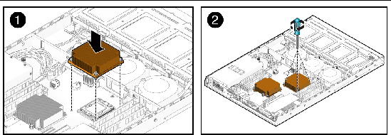
12. Reinstall the air duct and the system cover.
This section provides procedures for replacing the SATA cable, I/O board cable, and the disk power harness.
FIGURE 3-41 shows the routing of the cables and motherboard connector locations.
FIGURE 3-41 Cable Routing and Motherboard Cable Connections
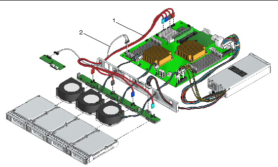
TABLE 3-3 lists the cables that are included with the X2270 server.
To remove the SATA cable harness:
1. Power off the system and remove the cover as described in Powering Off the Server and Removing the Cover.
2. Disconnect the SATA cables from the HDDs.
3. Disconnect the SATA cables from the motherboard connections.
4. Release the SATA cable harness from its tie-down points.
5. Carefully pull the SATA cable through the cutout in the chassis divider and lift it from the chassis.
To install the SATA cable harness:
1. Match the color-coded SATA cables with their associated motherboard connections, and reconnect the SATA cables to the motherboard.
2. Carefully route the SATA cable through the cutout in the chassis divider.
3. Reconnect the SATA cables to the HDDs.
4. Reattach the SATA cable to its tie-down points.
5. Check the routing of all cables for obstructions, and then reinstall the cover as described in Powering Off the Server and Removing the Cover.
1. Power off the system and remove the cover as described in Powering Off the Server and Removing the Cover.
2. Disconnect the I/O cable from the I/O board.
3. Disconnect the two I/O cable connections from the motherboard.
4. Carefully pull the I/O cable through the cutout in the chassis divider and lift it from the chassis.
1. Reconnect the two I/O cable connections to the motherboard.
2. Carefully route the I/O cable through the cutout in the chassis divider and over the top of the HDD partition.
3. Reconnect the I/O cable to the I/O board.
4. Check the routing of all cables for obstructions, and then reinstall the cover as described in Powering Off the Server and Removing the Cover.
To remove the HDD power harness:
1. Power off the system and remove the cover as described in Powering Off the Server and Removing the Cover.
2. Disconnect the power cables from the HDDs.
Starting with fixed disk 3 and working toward fixed disk 0, disconnect the power cables from each disk drive.
3. Release the HDD power harness from its tie-down points.
4. Disconnect the HDD power harness from the power supply unit.
To install the HDD power harness:
1. Reconnect the HDD power harness to the power supply unit.
2. Reconnect the power cables to the HDDs.
Starting with fixed disk 3 and working toward fixed disk 0, reconnect the power cables to each disk drive.
3. Reattach the HDD power harness to its tie-down points.
4. Check the routing of all cables for obstructions, and then reinstall the cover as described in Powering Off the Server and Removing the Cover.
The following procedures describe how to remove and install the Sun Fire X2270 Server system motherboard.
| Note - The motherboard is not a CRU and should be replaced only by trained field service technicians. |
1. Power off the system and remove the cover as described in Powering Off the Server and Removing the Cover.
2. Remove the PCIe card, the air duct, and if installed, the optional SP module.
For more information, see Replacing the PCIe Card, Replacing the Air Duct), and Removing and Replacing the SP Module).
3. Disconnect all cables attached to the motherboard.
4. Remove the four screws from the CPU heatsink (4 screws per heatsink installed).
5. Using a Phillips screwdriver, remove the eight screws that fasten the motherboard to the chassis.
FIGURE 3-42 Removing the Motherboard
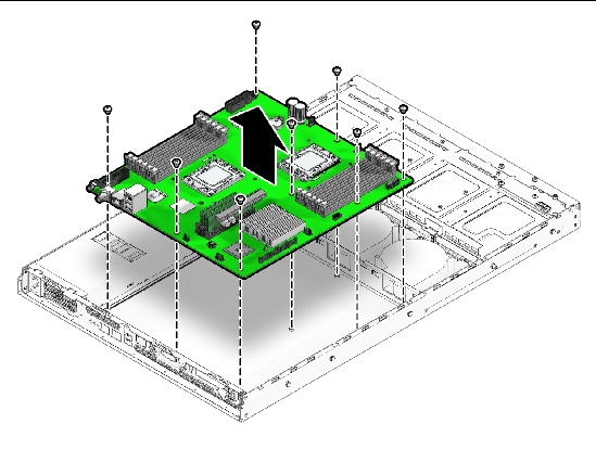
6. Pull the motherboard away from the chassis.
7. Remove the CPU and memory modules.
Refer to the following sections for information on removing and replacing the CPU and memory:

|
Caution - Observe proper ESD precautions in ESD Precautionswhen handling the new motherboard. |
1. Center the motherboard on the chassis so that the screw holes in the motherboard align with the screw holes on the chassis.
2. Secure the eight Phillips screws that fasten the motherboard to the chassis. Torque screws to 8-9 inch-pounds.
FIGURE 3-43 Installing the Motherboard
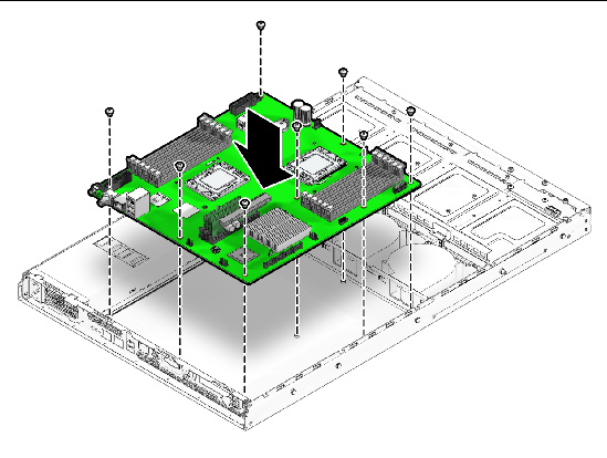
3. Replace the CPU and DIMMs as necessary.
See the following sections for information:
4. Replace the PCIe card, air duct, and if installed, the optional SP module.
See the following sections for information:
5. Reconnect all internal system cables.
See the following section for information:
6. Replace the air duct and system cover.
7. Replace any external cables and power on the server.
Copyright © 2009 Sun Microsystems, Inc. All rights reserved.