| Sun Fire X4500/X4540 Server Service Manual |
| C H A P T E R 3 |
|
Maintaining the Sun Fire X4500 and X4540 Servers |
This chapter covers the following topics:
The Sun Fire X4500/X4540 server can be serviced with the following items:
The following component replacements require additional tools:
FIGURE 3-1 shows the locations of the replaceable components that are documented in this chapter.
FIGURE 3-1 Sun Fire X4500/X4540 Replaceable Component Locations

This section lists Sun Fire X4540-supported FRUs/CRUs compatibility with the supported BIOS versions and other FRUs/CRUs.
The following table lists System Controllers supported by the Sun Fire X4540 server and their compatibility with supported CPUs, BIOS versions and HyperTransport 3.0.
The following table shows FRUs and CRUs supported by the Sun Fire X4500 and X4540 servers and their compatibility with other FRUs/CRUs.
| Note - The chassis FRUs are for replacing failed chassis or backplanes, and not for upgrading the chassis. |
The third power supply is not supported in x4500 systems and is only supported in X4540 systems originally manufactured with either of the following CPUs:
Three PSUs are fully redundant at 110 VAC and provides resiliency against a power supply failure. If one power supply fails, the remaining two power supplies will continue to operate the system. Two PSUs does not provide power redundancy and is not supported.
To order the third PSU, you must first determine that the x4540 system is compatible with a third power supply (see conditions above), then order the following parts:
| Note - The third power supply is not supported in an older X4540 (#541-1218) or the Sun Fire X4500 system. |
| Note - When a system is configured for 3 PSUs at 100-120V AC and only 2 PSUs are installed, the amber System Fault LED LED illuminates. |
For power supply part numbers, see Replacing a Power Supply (CRU).
The following 2356 CPUs are supported by the X4540:
The following 2384 CPUs are supported by the X4540:
The following 2384 CPUs are supported by the X4540:
Various types of disk drives are supported on the Sun Fire X4540 server.
| Note - Do not mix drives with different drive capacities. |
For a list of supported drives, see To Replace a Hard Drive (CRU).
1. Use SSH to log into the sunservice account using the default password, changeme.
# ssh SP-IP-address -l sunservice
# SP-IP-address password: changeme
2. At the prompt, enter the servicetool command to indicate that you have changed the board.
# servicetool --board_replaced=name_of_board
# servicetool --board_replaced=mainboard
a. name_of_board is mainboard (that is, the system controller).
b. service_processor is the X4500 GRASP board or the X4540 system processor.
| Note - Type servicetool at the SP prompt without options to see help screens which provide hints about options. The options are defined in the table below. |
|
Update FRU information for BOARD after board has been replaced. |
|
3. Reboot the server. Watch the output from the command and respond to the confirmation prompts for continuing the update and rebooting the server:
Servicetool is going to collect system information for the service processor for future part swaps.
The following preconditions must be true for this to work:
* The new service processor must be installed.
Do you want to continue (y|n)? y
Service processor FRU information ready to be collected.
You MUST reboot the service processor to complete
this process. Allow the service processor to fully boot.s
DO NOT UNPLUG THE SYSTEM WHILE THE SERVICE PROCESSOR IS BOOTING!
Would you like to reboot the service processor now (y|n)?y
The system is going down NOW !!
Sending SIGTERM to all processes.
4. Verify the FRU information is updated:
a. Once the SP has rebooted, log into sunservice.
cat /var/log/frutool.log
c. Make sure the last line is:
frutool::info::all FRUs updated successfully
d. Make sure the following is true:
i. Product part_number matches the part number on the back of the system.
ii. Product serial_number matches the serial number on the back of the system.
iii. If the part number or serial number does not match, contact your Sun representative.
e. To verify a FRU update procedure use the following CLI or ipmitool to verify the updates.
show /sys or ipmitool
ipmitool -Hlocalhost -Uroot -Pchangeme fru list
Use the procedures in this section when you are referred to them from the removal and replacement procedures. This section covers the following topics:
1. Choose a method for shutting down the server from main power mode to standby power mode. See .
Graceful shutdown: Use a nonconducting stylus or pointed device to press and release the recessed Power button on the front panel. This causes Advanced Configuration and Power Interface (ACPI) enabled operating systems to perform an orderly shutdown of the operating system. Servers not running ACPI-enabled operating systems will shut down to standby power mode immediately.
Emergency shutdown: Press and hold the Power button for four seconds to force the main power off and enter standby power mode.
When the main power is off, the Power/OK LED on the front panel begins flashing, indicating that the server is in standby power mode.
FIGURE 3-2 Sun Fire X4540 Server Front Panel

2. Unplug both power cords from the server’s power supplies.
3. Turn off all peripheral devices connected to the system.
4. Label any peripheral cables and telecommunication lines that must be disconnected in order to remove and replace a specific component.
This procedure assumes you have turned off the server, removed the cable management arm, and removed any cables or cords that would restrict the movement of the server.

|
Caution - To avoid serious personal injury and equipment damage while handling or moving this product, always use all four chassis handles to support the product weight. |

|
1. If you need to lighten the server, you can remove following from the rack:
To remove power supplies, see To Remove a Power Supply (CRU).
To remove the cable management assembly if necessary. See one of the following docs depending on your CMA version:
i. Sun Fire X4500/X4540 Installation Guide
ii. Sun X4500-J Slide Rail Installation Guide (X4500)
iii. Early-Production Slide Rail and CMA Information (X4500)
To remove the system controller, see Replacing the System Controller (FRU).
2. From the front of the rack, squeeze the slide-rail locks (with green plastic handles) to release the lock and pull the server about 1.5 inches from the rack.
3. Push the green plastic tabs on the middle slide rails to release the first stop.
4. Push the green plastic tabs on the middle slide rails to release the second stop and pull the server out about 36 inches (about 90 cm) from the rack.
5. If you need to lighten the server, open the disk drive access cover and remove the disk drives.
See To Remove the Drives Access Cover.
6. Slide the server completely out of the slide rails and place on a clean, stable surface.
|
The drives access cover protects the 48 drives in the server and ensures proper cooling to the drives and the system controller. To access the drives, you must first remove the drives access cover.
|
|
Caution - When the server is on, the drives access cover must be in place to ensure proper cooling. Do not remove the cover for more than 60seconds when the server is on. |
1. Using a No. 2 Phillips screwdriver, loosen the left and right captive screws. See FIGURE 3-3.
2. Grasp the cover by its edges, lift the front up from the chassis, and pull it forward.
FIGURE 3-3 Removing the Drives Access Cover (X4500 shown)

|
1. Postion the cover onto the rear of the chassis so that the cover’s metal lip slides under the chassis.
|
|
Caution - Be careful not to damage the drives light pipes at the rear of the system. |
|
|
Caution - Be careful not to jam the drives access cover intrusion switch when you replace the cover. See FIGURE 3-4. |
FIGURE 3-4 Drives Access Cover Intrusion Switch

2. Lower the cover and push it toward the rear until the front end drops into place.
3. Using a No. 2 Phillips screwdriver, turn the left and right screws on the cover until they are hand-tightened. See FIGURE 3-5.
FIGURE 3-5 Installing the Drives Access Cover
The I/O board and SP MAC addresses are printed on their respective PC boards, but they are also printed on the system controller handle. The locations appear in FIGURE 3-6.
FIGURE 3-6 MAC IDs on System Controller Handle

This section contains procedures for replacing the following components:

|
Caution - Before handling components, attach an antistatic wrist strap to bare metal on the chassis (see FIGURE 3-31for the location). The system’s printed circuit boards and disk drives contain components that are extremely sensitive to static electricity. |
For procedures on installing the Cable Management Arm and the Cable Management Bar, see one of the following documents:
For procedures on installing the chassis slide rails, see, X4500-J Slide Rail Installation Guide (820-7238).
This section describes how to remove and replace the power distribution board (PDB), which is also called the power backplane. Be sure you have the tools necessary as described in Section 3.1, Tools and Supplies Needed.
| Note - This component is a FRU and should be replaced only by qualified service technicians. Contact your Sun Service representative for assistance. |
This component replacement requires the following tools in addition to the tools listed in Section 3.1, Tools and Supplies Needed:
TABLE 3-7 lists the qualified part numbers for this component. These part numbers are subject to change over time. For an updated list of components, see the following web site:
http://sunsolve.sun.com/handbook_pub/Systems/
|
See Section 2.2, Powering Off the Server including unplugging all cables from the enclosure.
2. Remove the system controller.
See Replacing the System Controller (FRU).
See To Remove a Power Supply (CRU).
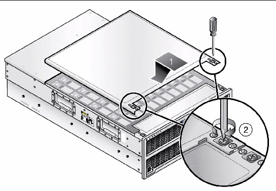
4. From the back of the enclosure, remove the power supply cover.
Using a No. 1 Phillips screwdriver, remove the two screws on the power supply cover. Pull the cover toward the rear of the chassis and lift. Some extra effort may be required to disengage the eight mushroom-head pins that secure the power supply cover to the chassis (see FIGURE 3-7).
FIGURE 3-7 Removing the Power Supply Area Cover

|
Pull cover toward you to disengage the eight mushroom head pins. |
|
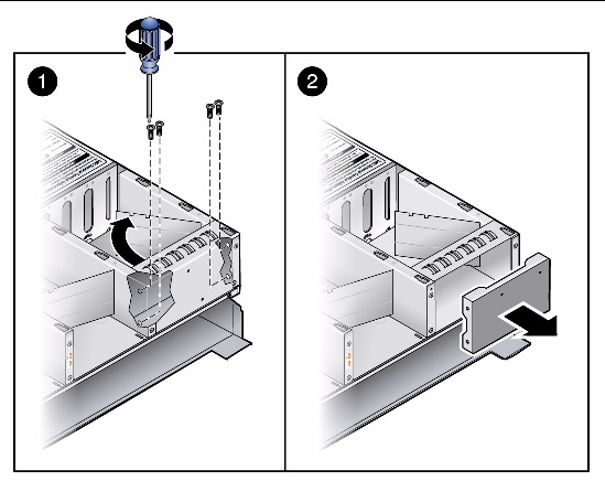
5. Remove the cable management arm (CMA) mounting plate (power supply filler panel).
You must remove the CMA mounting plate to get access to one of the screws that attaches the PDB to the chassis.
a. Push back the power supply swing door so you can access the area behind the CMA mounting plate.
b. Use a No. 2 Phillips screwdriver to remove the four screws that attach the CMA mounting plate to the bay, as shown in FIGURE 3-8.
FIGURE 3-8 Removing the CMA Mounting Plate
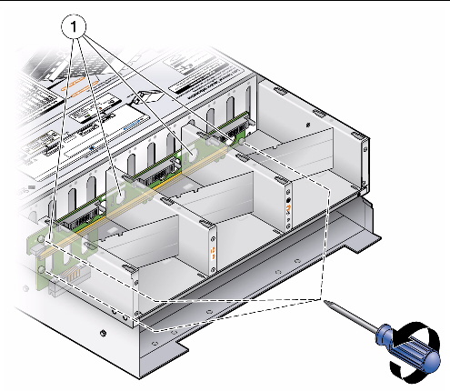
a. Remove the disk drive access cover.
See To Remove the Drives Access Cover.
b. Use a No. 1 Phillips screwdriver to loosen the three captive screws that secure the PDB to the chassis. See 1 in FIGURE 3-9.
FIGURE 3-9 Removing the Power Distribution Board
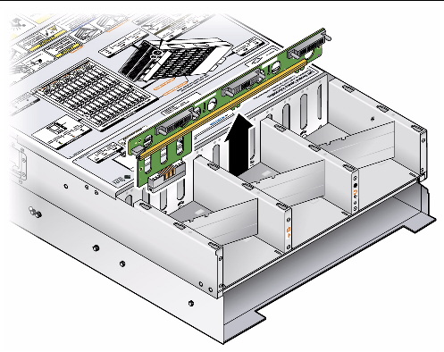
c. Put your fingers in the holes to pull the PDB up and then out of its keyed openings from the chassis standoffs. See FIGURE 3-10.
|
|
Caution - Be careful not to damage the intrusion switch located at the upper-left side of the PDB. The intrusion switch detects the removal of the system controller and cover. |
FIGURE 3-10 Pulling Out the Power Distribution Board
a. Align the new PDB so that the chassis standoffs protrude through its keyed openings, and then slide the PDB downward to lock it into place.
b. Push down on the edge of the board.
c. Use a No. 1 Phillips screwdriver to tighten the three captive screws that secure the PDB to the chassis. See FIGURE 3-9.
d. Verify that the disk drive access cover intrusion switch is functioning correctly and is not bent during installation of the PDB. See To Install the Drives Access Cover.
8. Reinstall the CMA mounting plate.
| Note - Skip this step if your chassis has a third power supply--this bay will be filled with the third power supply. |
9. Reinstall the power supply cover.
a. Align the mushroom-head pins with the indentations in the cover. This ensures that the intrusion switch is not blocked. For the locations of the mushroom-head pins, see FIGURE 3-7.
b. Push down on the cover and then slide the cover forward into place.
c. Replace the two screws at the rear of the power supply cover.
10. Install or reinstall the power supplies:
| Note - For a list of supported power supplies by part number, see Replacing a Power Supply (CRU). |
a. Align the power supply with the empty bay in the chassis.
b. With the power supply handle in the down position, push the power supply into the bay. It will stop about three-quarters of the way in when it meets the connector on the PDB.
c. Lift the power supply handle up until the power supply fully engages with the PDB (indicated when the thumb-latch clicks into place). The power supply should be flush against the chassis.
See Replacing a Power Supply (CRU).
11. Reinstall the system controller.
See Replacing the System Controller (FRU).
12. Reinstall the disk drive access cover.
See To Install the Drives Access Cover.
13. Reconnect AC power cords to the power supplies.
|
Each fan module (also known as a fan tray) has two fans. The server has five fan modules (10 fans per server). This component is customer replaceable.
| Note - This component can be replaced by anyone. |
TABLE 3-8 lists the qualified part numbers for this component. This part number is subject to change over time. For an updated list of components, see the following web site:
http://sunsolve.sun.com/handbook_pub/Systems/
Fans are labeled FT0 (fan tray 0) to FT4 (fan tray 4). See Locations of Components.
1. If the server is in a rack, slide it far enough out of the rack so that you can access the fan modules.
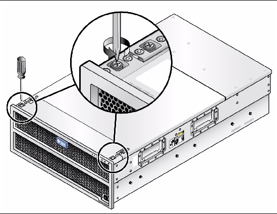
2. From the front of the enclosure, open the fan tray access cover.
Using a No. 2 Phillips screwdriver, loosen the two captive screws on the left and right sides. See FIGURE 3-11.
FIGURE 3-11 Removing the Fan Tray Cover
3. Identify the defective fan module.
A defective fan module shows a lit amber (middle) LED: The fan should be replaced.
|
|
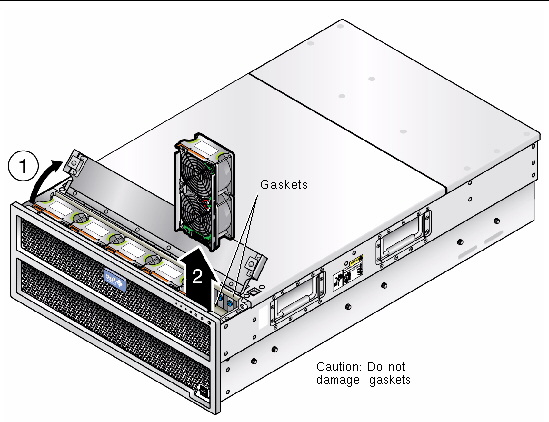
Caution - Be careful to not damage the gaskets when you remove the fan module. |
Using your thumb and forefinger, grasp the top handle of the fan module and lift the module up and out of the chassis. See FIGURE 3-12.
FIGURE 3-12 Removing a Fan Module
5. Install the new fan module:
a. Align the new fan module with the bay in the chassis.
b. Lower the fan tray into the bay until it comes into contact with the connector on the fan board.
c. Push down gently until the connector is fully engaged.
Once fully engaged, the amber LED (middle) on the fan tray may light momentarily.
6. Close the fan cover and tighten the retaining screws on the left and right sides of the cover.
|
The front indicator board supports the front panel power button and front panel indicator LEDs. This board also contains the ribbon cable that connects to the disk drive backplane. Be sure you have the tools necessary as described in Tools and Supplies Needed.
| Note - This component is a FRU and should be replaced only by qualified service technicians. Contact your Sun Service representative for assistance. |
This component replacement requires a No. 1 Phillips screwdriver (magnetic tip recommended).
TABLE 3-9 lists the qualified part numbers for this component. This part number is subject to change over time. For an updated list of components, see the following web site:
http://sunsolve.sun.com/handbook_pub/Systems/
| Note - If you suspect the ribbon cable is bad, first replace the cable that connects the front indicator board to the disk drives backplane and then test the operation of the front indicator board. |
2. If the server is in a rack, slide it far enough out of the rack so that you can access the fan modules.
3. From the front of the enclosure, open the fan cover.
Using a No. 2 Phillips screwdriver, loosen the two captive screws on the left and right sides.
4. Remove fan tray 0 and fan tray 1.
5. Remove the disk drive access cover so that the fan cover opens more freely.
See To Remove the Drives Access Cover.
Using a No. 2 Phillips screwdriver, loosen the two captive screws on the left and right sides.
6. Using a No. 1 Phillips screwdriver, remove the three screws (see 1 in FIGURE 3-13) on the front indicator board, then remove (see 2 in FIGURE 3-13).
FIGURE 3-13 Removing the Front Indicator Board Screws

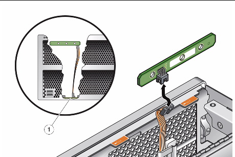
7. Detach the ribbon cable from the front indicator board, see FIGURE 3-14.
If you suspect that the ribbon cable is bad, remove the old ribbon cable from the disk drives backplane and use the new ribbon cable that comes with the new front indicator board. Make sure you route the cable through the cable securing clips to prevent damage to the cable. Then test the operation of the front indicator board as described in Section 2.1, Powering On the Server.
FIGURE 3-14 Detaching the Ribbon Cable from the Disk Drives Backplane
|
Detatch the ribbon cable connector from the disk drive backplane. |
8. Install the new front indicator board:
a. Align the holes in the indicator board with the two screw holes in the inside-front of the chassis.
b. Using a No. 1 Phillips screwdriver, replace and tighten the two screws that secure the indicator board to the chassis.
c. Connect the ribbon cable to the connector on the disk drives backplane and to the connector on the front indicator board.
9. Replace fan module 0 and fan module 1.
10. Close the fan cover and, using a No. 1 Phillips screwdriver, tighten the two screws on the left and right sides.
11. Replace the disk drives access cover and, using a No. 1 Phillips screwdriver, tighten the two screws on the left and right sides. See Section t, To Remove the Drives Access Cover.
|
This section describes how to remove and replace a drive. It is a good practice to allocate five drives (roughly 10 percent of the total capacity) as hot spares.
The system designation of the drives is shown on the service label.
TABLE 3-10 lists the qualified part numbers for this component. These part numbers are subject to change over time.
| Note - Do not mix drives of different drive capacities. |
For an updated list of components, see the following web site:
http://sunsolve.sun.com/handbook_pub/Systems/
For a list of compatible SSDs, see Replacing a Solid-State Drive (Sun Fire X4540 CRU).
| Note - Before removing a drive, have the replacement drive ready to be installed. |
For supported solid-state drives and their part numbers, see Replacing a Solid-State Drive (Sun Fire X4540 CRU).
| Note - Early fan trays had a blue LED that was not activated. Later versions of the fan trays have only a green and amber LED. |
1. Remove the drives access cover.
See To Remove the Drives Access Cover.
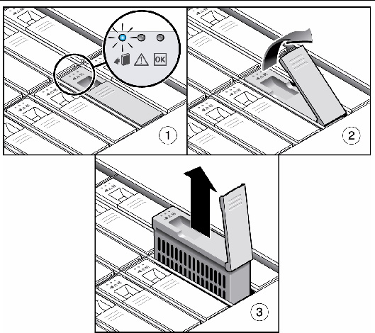
2. Identify the drive to be removed by checking its LEDs.
If the middle LED is on (amber), the drive is faulty and should be replaced.
3. Use the operating system or management software to take the disk drive offline before you replace it. Not doing so could cause data loss or unexpected error messages.
Once the drive has been taken off line, the left (blue) LED should turn on. This means the drive is ready to be removed and service action is allowed.
|
|
Caution - Pulling a drive that has that has not been prepared for removal can cause a loss of the drive cell memory map or loss of data in its in/out buffers. |
4. Remove the drive. Lift the metal latch and remove the drive from the drive bay as shown below, or on the service label.
FIGURE 3-15 Removing a Hard Disk Drive or Solid-State Drive

5. Install the new drive of the same capacity as the one removed.
Push the drive into the bay until it stops, and make sure the drive is fully engaged with the connector on the drives backplane.
6. Make sure the metal handle is properly seated.
7. Replace the disk drives access cover.
See To Install the Drives Access Cover.
Refer to your operating system documentation for information on adding a new disk drive.
Higher performance is gained with SSDs over standard drives because SSDs enable the system to be used as cache memory for ZFS.
The following are important hardware rules and cautions when using SSDs:
The following are important restrictions when using SSDs:
| Note - For an updated list of components, see the following web site: http://sunsolve.sun.com/handbook_pub/Systems/ |
|
| Note - Before removing a drive, have the replacement drive ready to be installed. |
Use this procedure to remove a drive prior to installing an SSD. This procedure applies to hard drives and SSDs.
1. Remove the drives access cover.
See To Remove the Drives Access Cover.
2. Identify the drive to be removed by checking its LEDs.
If the middle LED is on (amber), the drive is faulty and should be replaced.
3. Use the operating system or management software to take the disk drive offline before you replace it. Not doing so could cause data loss or unexpected error messages.
Once the drive has been taken off line, the left (blue) LED should turn on. This means the drive is ready to be removed and service action is allowed.
|
|
Caution - Pulling an SSD that has that has not been prepared for removal can cause a loss of the drive cell memory map or loss of data in its in/out buffers. |
4. Remove the drive. Lift the metal latch and remove the drive from the drive bay as shown below, or on the service label.
FIGURE 3-16 Removing a Hard Disk Drive or Solid-State Drive
5. Install the SSD (in drive bracket) into the drive bay of the system.
Push the drive into the bay until it stops and is fully engaged with the connector on the drive backplane. Push down the metal handle so it properly locks into place.
FIGURE 3-17 Installing the SSD into the System

6. Replace the disk drives access cover. See To Install the Drives Access Cover.
7. Configure the new disk drive.
Refer to your operating system documentation for information on adding a new disk drive.
This section describes how to remove and replace a power supply unit (PSU).
Two PSUs are fully redundant at 220 VAC; if one power supply fails, the second power supply will continue to operate the system. One PSU is not supported, and causes the System Fault LEDs to illuminate.
Three PSUs are fully redundant at 110 VAC; if one power supply fails, the remaining two power supplies will continue to operate the system. Two PSUs does not provide power redundancy, is not supported, and causes the System Fault LEDs to illuminate.
| Note - This component is a hot-swappable CRU and can be replaced by qualified personnel. Hot-swappable means you do not need to power off the server during replacement. |
TABLE 3-12 lists the qualified part number for this component. These part numbers are subject to change over time. For an updated list of components, see the following web site:
http://sunsolve.sun.com/handbook_pub/Systems/
|
Power supply, (type A240), 1500W, 110 VAC, (X4540, 3 per system) |
The system designation of the two power supplies in the server is shown on the service label.
|
| Note - If you are installing the third power supply, you must first remove the power supply cover and cable management arm mounting plate (power supply filler panel). |
1. From the back of the enclosure, remove the power supply cover.
2. Using a No. 1 Phillips screwdriver, remove the two screws on the power supply cover.
Pull the cover toward the rear of the chassis and lift. Some extra effort may be required to disengage the eight mushroom-head pins that secure the power supply cover to the chassis. See FIGURE 3-18.
FIGURE 3-18 Removing the Power Supply Area Cover
|
Pull cover toward you to disengage the eight mushroom head pins. |
|
3. Remove the cable management arm (CMA) mounting plate (power supply filler panel).
a. Push back the power supply swing door so you can access the area behind the CMA mounting plate [1].
b. Use a No. 2 Phillips screwdriver to remove the four screws that attach the CMA mounting plate to the bay [2]. See FIGURE 3-8.
FIGURE 3-19 Removing the CMA Mounting Plate

|
This section describes how to remove a power supply unit (PSU).
The power supplies are fully redundant at 220 VAC; if one power supply fails, the other power supply will continue to operate.
| Note - This component is hot-swappable. Hot-swappable means you do not need to power off the server during replacement. |
The system designation of the power supplies in the server is shown on the service label.
1. If present, remove the cable management arm, or swivel open the cable management arm to view the power supplies.
To replace the cable management assembly if necessary. See one of the following docs depending on your CMA version:
2. Disconnect the AC power cord that is connected to the power supply you want to replace.
3. Remove the installed power suppy unit by pulling its handle downward until it disengages the unit from the connector on the PDB. Pull out the power supply.
|
1. Align the power supply with the empty bay in the chassis.
2. With the power supply handle in the down position, push the power supply into the power supply bay.
The power supply will stop about three-quarters of the way into the bay when it meets with the connector on the PDB. Lift the power supply handle up until the power supply fully engages with the PDB (indicated when the thumb-latch clicks into place). The power supply should be flush against the chassis.
3. Connect the AC power cord to the new power supply. Use the power cord retaining clips to keep the power cord secure.
4. If present, swivel the cable management arm back into the closed position.
|
| Note - This component is a CRU and can be replaced by anyone. |
Follow these steps to remove and replace the system battery.
TABLE 3-13 lists the qualified part number for this component. These part numbers are subject to change over time. For an updated list of components, see the following web site:
http://sunsolve.sun.com/handbook_pub/Systems/
1. Power off the server as described in Section 3.7.1, Powering Off the Server.
2. Remove the cable management arm.
See one of the following depending on your system:
3. Remove the system controller as described in To Remove the System Controller (CRU).
4. Remove the battery by gently pulling the clip away from the battery face and lifting the battery straight up. See FIGURE 3-20 (the X4500 system is shown).
FIGURE 3-20 Removing the Battery

5. To install a new battery, gently pull the clip away and insert.
| Note - Install the new battery in the holder with the same orientation (polarity) as the battery that you removed. |
6. In some cases for the battery to work, you might need to reset the CMOS on the I/O controller board.
To reset the CMOS, use a screwdriver to short the pins for one or two seconds on jumper J27 on the I/O controller board. Jumper J27 is near the serial connection to the service processor (labeled SER MGT) on the back of the server. See FIGURE 3-21 (the X4500 system is shown).
FIGURE 3-21 Location of Jumpers on the I/O Controller (X4500)
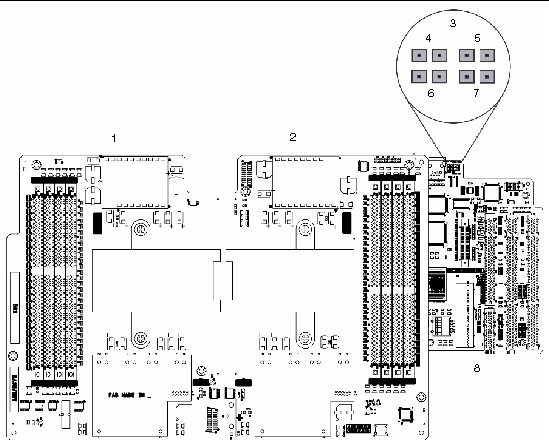
FIGURE 3-22 Location of Jumpers on the I/O Controller (X4540)

|
This section describes how to remove and replace a CPU.
| Note - This component is a FRU and must be replaced only by qualified service technicians. Contact your Sun Service representative for assistance. |
| Note - To migrate your Sun Fire X4500 to an X4540, see the Sun Fire X4500 to X4540 Migration Guide. |
TABLE 3-14 lists the qualified part numbers for this component. These part numbers are subject to change over time. For an updated list of components, see the following web site:
http://sunsolve.sun.com/handbook_pub/Systems/
The System Controller Fault LED on the system controller indicates a problem with either the CPUs or the DIMMs. For the location of this LED, see FIGURE 3-31. This Fault LED is powered by 3.3V standby power.
DIMM and CPU fault LEDs on the CPU module provide further indications of which component has a fault condition. These CPU and DIMM fault LEDs can be lit for up to one minute by a capacitor on the CPU module, even after the CPU module is removed from the server. To light the fault LEDs from the capacitor, push the small button on the CPU board labeled, “Press to see fault.”
See FIGURE 3-23 for the LED and button locations.
Off: CPU and DIMMs are functioning properly.
On (amber): CPU or DIMM is faulty.
DIMM fault LEDs are under the DIMM ejector levers that are toward the front of the system:
Off: The DIMM is operating properly.
On (amber): The DIMM is faulty and must be replaced.
Off: The CPU is operating properly.
On (amber): The CPU is faulty and must be replaced.
Off: The battery is operating properly.
On (amber): The battery is faulty and must be replaced.
| Note - The CPU fault and DIMM LEDs continue to indicate a failure until the system is powered up. The Battery LED continues to indicate a failure until the service processor is started. |
See Section 3.7.1, Powering Off the Server.
2. Remove the cable management arm.
See one of the following depending on your system:
3. Remove the system controller.
See To Remove the System Controller (CRU).
The CPUs are located inside the system controller.
4. Identify which CPU module you are replacing, either CPU 0 or CPU 1.
The CPUs are labeled. See FIGURE 3-23 (the X4500 system is shown).
FIGURE 3-23 CPU Board LED and Button Locations (X4500)

FIGURE 3-24 CPU Board LED and Button Locations (X4540)

1. Remove the heat sink for the faulty CPU. See FIGURE 3-25 (the X4540 system is shown).
FIGURE 3-25 Removing the Heat Sink (X4540 shown)

a. Using a No. 2 Phillips screwdriver, loosen one screw two to three turns and then loosen the other screw two to three turns. Alternate between the two screws until you can remove the screws.
b. Gently twist the heat sink and pull it off.
| Note - Set the heatsink upside down on a clean, flat surface to prevent the thermal grease from contaminating other components. |
| Tip - As you pull off the heat sink, the springs in the heat sink screws might pop out. Be prepared to retrieve them. |
5. Remove the CPU by pulling the socket release lever out and up. See FIGURE 3-26 (the X4540 system is shown).
FIGURE 3-26 Removing the CPU (X4540 shown)

6. Use the included alcohol pad to remove all thermal grease from the bottom of the heat sink.
7. Inspect the heat sink for dust and lint. Clean if necessary.
9. Install the new CPU, or reinstall the existing CPU.
| Note - Mixing CPU speeds or mixing dual-core CPUs with single-core CPUs is not supported. Use two identical CPUs in your server. |
| Note - Align the triangle that is printed on one corner of the CPU with the tiny triangle that is imprinted on the CPU socket, as shown in the red circle in FIGURE 3-27. |
a. Ensure that the CPU socket release lever is in the fully open, vertical position.
b. If re-using the existing heatsink, clean and regrease it.
c. Use an alcohol pad to clean all the old thermal grease from the component surface. Also, clean the dust from the heatsink fins.

d. Using one syringe of thermal grease (0.2 ml/0.5 g), carefully apply grease to the top of the CPU in three lines in the pattern shown in FIGURE 3-27.
| Note - Two syringes of thermal grease are supplied with the new CPU, but use only one syringe for each CPU. Apply the grease in the pattern shown in FIGURE 3-27. |
FIGURE 3-27 Required Pattern for Thermal Grease Application
.")
10. Align the CPU to the socket.
a. Gently insert the CPU pins into the socket.
| Tip - Align the gold triangle on the CPU with the white triangle on the socket. Also note the location of the keys (notches) on the CPU. |
11. When the CPU is fully seated in the socket, pivot the release lever down until it is locked into position, at the side of the socket.
12. Ensure that the foam strip under the heat sink area is intact and that it has not been removed, loosened, or damaged. This foam strip is critical to proper air flow.
13. Carefully position the heat sink onto the CPU, aligning it with the mounting posts to reduce movement after it makes initial contact with the layer of thermal grease.
14. Reinstall the heat sink by using a No. 2 Phillips screwdriver to secure the two screws.
a. Tighten one screw two to three turns and then tighten the other screw two to three turns.
b. Alternate between the two screws until they are firmly attached.
15. Return the system controller cover and tighten the three captive screws.
16. Replace the cable management arms and return the system controller to the server.
|
This section describes how to remove and replace the Graphics Redirect and Service Processor (GRASP) board also known as the service processor board.
| Note - After you replace the GRASP board FRU, you must use the servicetool command to update FRU information about the board. See Section 3.6, Servicetool FRU Update Procedure. |
The GRASP board has one status LED. See Section C.3, GRASP Board LED (Sun Fire X4500) for the LED location.
TABLE 3-15 lists the qualified part numbers for this component. These part numbers are subject to change over time. For an updated list of components, see the following web site:
http://sunsolve.sun.com/handbook_pub/Systems/
|
Graphics Service Processor (GRASP) board, includes SP board and video board |
1. Power off the server as described in Section 3.7.1, Powering Off the Server.
2. Remove the cable management arm as described in one of the following:
3. Remove the system controller as described in To Remove the System Controller (CRU).
|
|
Caution - There is a power status LED (CR1) on the GRASP board that indicates whether 3.3V standby power is reaching the GRASP board (see FIGURE 3-28). The GRASP board is nothot-swappable and must never be removed while this LED is lit. |
| Note - The GRASP board removal procedure only applies to the X4500 server. |
|
|
Caution - Do not bend the GRASP board while removing it or installing it. |
Carefully hold the board and lift to detach it from the left metal connector and from the bottom connectors on the I/O board.
FIGURE 3-28 Removing the GRASP Board (X4500 shown)
.")
5. Install the new GRASP board.
Align the GRASP board so that its connectors align with the metal tab on the left, and with the bottom connectors on the I/O board. Then push the board into place.
6. Return the system controller and the cable management arm to the server.
See Replacing the System Controller (FRU).
7. Replace the cable management assembly if necessary:
8. Update the FRU information using servicetool. See Section 3.6, Servicetool FRU Update Procedure.
|
This section describes how to remove and replace the server’s dual inline memory modules (DIMMs).
| Note - This component is a CRU and can be replaced by anyone. |
1. Power off the server as described in Section 3.7.1, Powering Off the Server.
2. Remove the cable management arm as described in one of the following:
3. Remove the system controller as described in To Remove the System Controller (CRU).
4. Locate the DIMM slot on the CPU board on which you want to install or replace a DIMM.
The DIMM fault LEDs in the DIMM slot ejector levers indicate which DIMM has failed. These DIMM fault LEDs can be lit for up to one minute by a capacitor on the CPU board. To light the fault LED from the capacitor, push the small blue button on the CPU board, labeled “Press to see fault.” See FIGURE 3-23 for the locations.
One end of the DIMM ejector levers contain LEDs that can indicate a faulty DIMM:
The system designation of the DIMM slots on each CPU board is shown in FIGURE 3-23 (the X4500 system is shown--4 DIMM slots).
FIGURE 3-29 Removing DIMMs on the CPU Board (X4540 shown)

5. Review the following list of memory configuration guidelines and the supported DIMM configurations listed in TABLE 3-16 before you remove or install any DIMMs.
DIMM population rules for the X4500:
DIMM population rules for the X4540:
a. Rotate both DIMM slot ejectors outward as far as they will go. The DIMM is partially ejected from the socket. See FIGURE 3-29.
b. Carefully lift the DIMM straight up to remove it from the socket.
|
TABLE 3-18 lists the qualified part numbers for this component. These part numbers are subject to change over time. For an updated list of components, see the following web site:
http://sunsolve.sun.com/handbook_pub/Systems/
1. Read Steps 1 through 5 in To Remove Memory Modules (DIMMs) (CRU).
a. Ensure that the DIMM slot ejectors at each end of the memory socket are fully open (rotated outward) to accept the new DIMM.
b. Align the notch in the bottom edge of the DIMM with the key in the DIMM socket. See FIGURE 3-29.
c. Press down evenly on both top corners of the DIMM until the ejectors snap over the cutouts in the left and right edges of the DIMM.
3. Replace the system controller to the server (X4500).
See Replacing the System Controller (FRU).
4. Replace the cable management assembly if necessary. See one of the following docs depending on your CMA version:
|
The Sun Fire X4500 accommodates up to two PCI-X cards and the X4540 servers accommodates up to three PCIe expansion cards that meet PCI 2.2 specifications and the PCI-X Mechanical and Electrical Addendum with the following limitations:
| Note - This component is a FRU and must be replaced only by qualified service technicians. Contact your Sun Service representative for assistance. |
Installing a PCI-X card is similar to installing the GRASP board.
For a list of supported PCI cards, see the following web site:
http://www.sun.com/servers/x64/x4540/optioncards.jsp
For an updated list of components, see the following web site:
http://sunsolve.sun.com/handbook_pub/Systems/
From this web site, click on the Sun Fire X4540 server, then on Full Components List for the list of components. The full description of the component is listed with a Buy button beside each one.
See Section 3.7.1, Powering Off the Server.
2. Remove the cable management assembly if necessary.
See one of the following docs depending on your CMA version:
3. Remove the system controller.
See To Remove the System Controller (CRU).
Align the PCI-X board connectors with the metal tab on the left and the bottom connectors on the I/O board. Then push the board into place. See FIGURE 3-28.
5. Replace the system controller.
See Replacing the System Controller (FRU).
6. Replace the cable management assembly if necessary. See one of the following docs depending on your CMA version:
|
This section describes how to replace the system enclosure, which includes the chassis, the disk drives backplane, and the front indicator board and ribbon cable.
| Note - This component is a FRU and must be installed only by qualified service technicians. Contact your Sun Service representative for assistance. |
TABLE 3-19 lists the qualified part numbers for this component. These part numbers are subject to change over time. For an updated list of components, see the following web site:
http://sunsolve.sun.com/handbook_pub/Systems/
See Section 3.7.1, Powering Off the Server.
2. Remove the cable management assembly if necessary.
See one of the following docs depending on your CMA version:
3. Remove the system controller.
See To Remove the System Controller (CRU).
See To Remove a Power Supply (CRU).
See To Replace a Fan Module (CRU).
6. Label the drives with adhesive notes (or another method) so that you will know where to reinstall the drives at the end of this procedure.
7. Remove all drives from the drive bays.
See To Replace a Hard Drive (CRU).
8. Remove old chassis from the rack.
See Removing the Server From the Rack
9. Install the new chassis into the rack.
See the Sun Fire X4540 Installation Guide.
10. Reinstall all drives to the new chassis.
11. Reinstall the power supplies into the new chassis.
12. Reinstall the fan modules into the new chassis.
13. Reinstall the system controller into the new chassis.
14. Reinstall the cable management arm.
This section describes how to remove and replace the system controller, which includes an I/O controller board and the CPU board. The server does not have a motherboard as a component; however, the I/O controller board and the CPU board together serve the function of a motherboard.
A replacement system controller does not include the CPU, memory (DIMMs), GRASP board (X4500) or Service Processor (X4540), or PCI cards. If these components are good, you must remove them from the old system controller and install them on the replacement system controller.
| Note - This component is a FRU and must be replaced only by qualified service technicians. Contact your Sun Service representative for assistance. |
TABLE 3-20 lists the qualified part numbers for this component. These part numbers are subject to change over time. For an updated list of components, see the following web site:
http://sunsolve.sun.com/handbook_pub/Systems/
1. Remove the cable management assembly if necessary.
See one of the following docs depending on your CMA version:
2. Remove the old system controller.
See To Remove the System Controller (CRU).
3. Move components to new system controller:
If the DIMMs, CPUs, heat sinks, optional PCI cards, and GRASP board (X4500) are operational and need to be moved to your new system controller, remove them from the old system controller:
a. See To Remove Memory Modules (DIMMs) (CRU) and To Install Memory Modules (DIMMs) (CRU).
b. See To Replace a CPU (FRU).
c. See To Replace the GRASP Board (X4500) (FRU).
d. See To Install a PCI-X or PCIe Card (FRU)
4. Reinstall the new system controller into the chassis.
See Replacing the System Controller (FRU).
5. Update the FRU information using servicetool.
See Section 3.6, Servicetool FRU Update Procedure.
|
The system controller consists of a sub-enclosure that can be removed from the back of the main system enclosure. The system controller contains the CPUs, memory, the service processor, and optional PCI cards.
|
|
Caution - To prevent electrostatic discharge (ESD) damage to the components on the system controller, connect a ground strap between yourself and the chassis ground before proceeding. |
1. Shut down the power from the front panel and then unplug both power supply cords.
2. Remove the CMA from the X4500 as described in one of the following:
See one of the following docs depending on your CMA version:
3. Unscrew the captive screw on the system controller handle.
FIGURE 3-30 Opening the Protective Handle on System Controller

4. Pull the system controller out of the chassis. See FIGURE 3-31.
5. Use the handle to pull the system controller from the chassis with one hand while supporting the system controller weight with the other hand.
FIGURE 3-31 Removing the System Controller

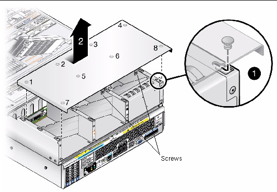
6. Loosen the two captive screws (with plastic green caps) under the system controller handle. See FIGURE 3-32.
FIGURE 3-32 Loosening Captive Screws and Removing the Cover

7. Remove the system controller cover.
Push the system controller cover toward the rear and lift it off the chassis.
|
TABLE 3-21 lists the qualified part numbers for this component. These part numbers are subject to change over time. For an updated list of components, see the following web site:
http://sunsolve.sun.com/handbook_pub/Systems/
1. Place the cover onto the system controller.
2. Hand tighten the two captive screws to secure the cover.
3. Align the system controller with the empty bay in the chassis.
Before replacing the system controller, make sure the cover is installed.
4. Push the system controller into the bay until it firmly engages with the connector on the power distribution board.
FIGURE 3-33 Replacing the System Controller
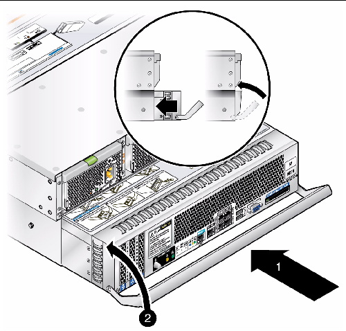
5. Push the system controller further until it is seated firmly. Close the system controller handle.
6. Lift the system controller handle until its latch clicks into place.
7. Connect the power cables to both power supplies and make sure to use the power cord retaining clips to keep power cords attached snugly.
8. Replace the cable management assembly if necessary.
See one of the following docs depending on your CMA version:
| Sun Fire X4500/X4540 Server Service Manual | 819-4359-19 |
Copyright © 2010, Oracle and/or its affiliates. All rights reserved.
 To Remove the Server From the Rack
