| C H A P T E R 1 |
|
Sun Netra X6270 M2 Server Module Hardware and Software Features |
This chapter summarizes the features available on the Sun Netra X6270 M2 server module and contains the following topics:
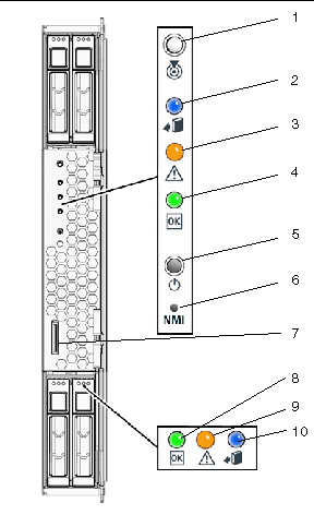
FIGURE 1-1 identifies the front panel buttons, indicators, and ports on the server.
FIGURE 1-1 Front Panel of the Server Module

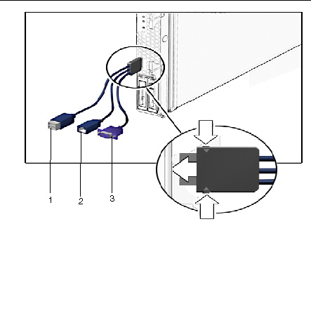
Your system chassis is shipped with a dongle cable that enables you to connect communication devices directly to the front panel of the server module:
| Note - The 3-Cable Dongle II is typically provided with each Sun Netra 6000 DC modular system. Additional cables may be ordered. |
You can use the VGA or USB connectors on the dongle cable to communicate with the server module BIOS and operating system. Or, you can use the serial connector to communicate with the server module SP.
FIGURE 1-2 illustrates how to attach the 3-Cable Dongle to the server module universal connector port (UCP).
FIGURE 1-2 Server Front Panel I/O Connection Using 3-Cable Dongle

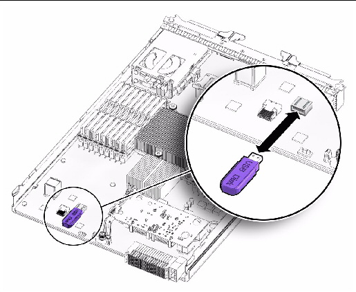
You can use a USB drive to communicate with the server module BIOS and operating system. FIGURE 1-3 illustrates how to attach the USB drive on the server module motherboard.
FIGURE 1-3 Attaching a USB Drive

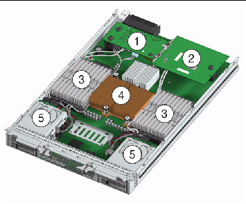
FIGURE 1-4 identifies the replaceable component locations with the top cover removed.
FIGURE 1-4 Replaceable Component Locations

|
Fabric Expansion Module (FEM) (optional component) Note - Inset (1a and 1b) shows motherboard-facing connections and replaceable components. See Installing or Servicing a Fabric Expansion Module (FEM). |
|
|
The DIMMs in FIGURE 1-4 are shown populated with filler panels. See Installing or Replacing Memory Modules (DIMMs). Note - Processor chip contains memory controller. Do not attempt to populate DIMMs sockets next to unpopulated (empty) CPU sockets. |
|
|
CPUs and heatsinks (up to two CPUs may be installed) See Replace or Upgrade CPU and Heatsink. The minimum CPU configuration shipped includes one CPU with a heatsink. An air baffle is shipped to cover the empty CPU socket (not shown in FIGURE 1-4). Additional CPUs may be ordered. Note - In the example shown in FIGURE 1-4, the CPUs are installed under the two heatsinks. |
|
|
Storage devices (hard disk drives or solid state drives) Up to four optional storage devices may be installed. See Installing or Servicing a Hard Disk Drive or Solid State Drive. |
Copyright © 2010, Oracle and/or its affiliates. All rights reserved.