| C H A P T E R 3 |
|
Maintaining the Sun Netra X6270 M2 Server Module |
This chapter contains information and procedures for servicing the Sun Netra X6270 M2 server module hardware.
This chapter contains the following topics:
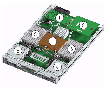
FIGURE 3-1 shows the locations of the replaceable components that are documented in this chapter.
FIGURE 3-1 Replaceable Component Locations
|
Fabric Expansion Module (FEM) (optional component) Note - Inset shows motherboard-facing connections and replaceable components. See Installing or Servicing a Fabric Expansion Module (FEM). |
|
|
The DIMMs in FIGURE 3-1 are shown populated with filler panels. See Installing or Replacing Memory Modules (DIMMs). Note - Processor chip contains memory controller. Do not attempt to populate DIMMs sockets next to unpopulated (empty) CPU sockets. |
|
|
CPUs and heatsinks (up to two CPUs may be installed) See Replace or Upgrade CPU and Heatsink. The minimum CPU configuration shipped includes one CPU with a heatsink. An air baffle is shipped to cover the empty CPU socket (not shown in FIGURE 3-1). Additional CPUs may be ordered. Note - In the example shown in FIGURE 3-1, the CPUs are installed under the two heatsinks. |
|
|
Storage devices (hard disk drives or solid state drives) Up to four optional storage devices may be installed. See Installing or Servicing a Hard Disk Drive or Solid State Drive. |
You can service the server with the following items:
Internal modules and options are electronic components that are extremely sensitive to static electricity. Ordinary amounts of static from your clothes or work environment can destroy components.
To prevent static damage whenever you are accessing any of the internal components, you must:
Use the preparatory procedures in this section when you are referred to them from the removal and replacement procedures.

|
Caution - Do not operate the system with empty slots. Always insert a filler panel into an empty slot to reduce the possibility of system shut down. |
To replace components for the Sun Netra X6270 M2 server module, with the exception of the hard disk drives, you need to remove the server module from the chassis.
| Note - If you are only replacing the hard disk drives in the server, you can skip this section and go to Installing or Servicing a Hard Disk Drive or Solid State Drive. |
1. Power off the server and verify that the server is ready to be removed from chassis.
For instructions, see Power Off and Verify Server Is Ready for Removal From Chassis.
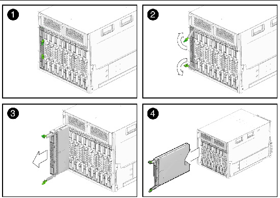
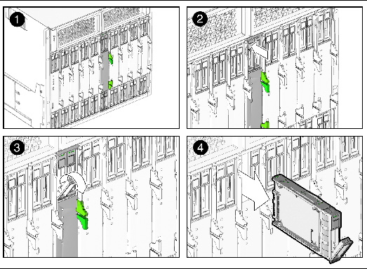
2. Perform the following steps to remove the server from the chassis.
See FIGURE 3-2.
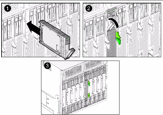
a. To open the ejector levers on the server: 1) press the green ejector button at the top and bottom to unlatch the server from chassis; then 2) swing out the top and bottom levers.
b. To slide the server from the chassis: 1) hold the opened ejector levers and pull the ejector levers toward you; then 2) grasp the server with both hands and slide it toward you away from the chassis.
FIGURE 3-2 Removing the Server From the Chassis
3. Place the server on a flat antistatic surface.
4. Install a server module filler panel in the unused server slot to ensure proper airflow throughout the system.

|
Caution - If you operate the chassis with an empty server module slot, it is possible that you will notice a reduction in the performance of your system. |
Each server module arrives with module-replacement filler panels for CPUs, storage drives, and memory modules. These filler panels are installed at the factory and must remain in the server module until you are ready to replace them with a purchased module.
A filler panel is a metal or plastic enclosure that does not contain any functioning system hardware or cable connectors. These panels must remain in any unused module slots (storage drives, DIMMs, and CPUs) to ensure proper air flow throughout the system. If you remove a filler panel and continue to operate your system with an empty module slot, the operating performance for your system could decline.
|
To remove or insert server module filler panels follow the procedures in TABLE 3-1.
| Note - For instructions for adding or replacing chassis component filler panels (for example, network modules or chassis monitoring modules), consult the documentation supplied with your chassis. |
Refer to the following instructions for removing or installing the cover on the server.
|
1. Press down on the cover release button and, using the indent for leverage, slide the main cover toward the rear of the chassis approximately 0.5 inch (12 mm).
See FIGURE 3-3.
FIGURE 3-3 Removing the Main Cover
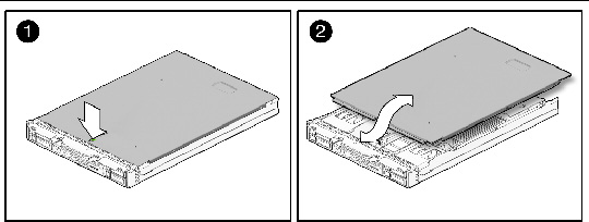
2. Grasp the cover by its rear edge and lift it straight up from the chassis.
|
1. Slide the cover under the tabs at the front of the server module.
2. Gently press down on the cover to engage it with the chassis.
3. When applicable, install the server in the chassis and power on the system.
For instructions, see the Sun Netra X6270 M2 Server Module Installation Guide, 821-0937.
Some of the procedures in this section are for customer-replaceable units (CRUs) and some are for field-replaceable units (FRUs), as noted in the procedures and in the list below. FRU components must be replaced only by trained service technicians. Contact your Service representative for assistance with FRU replacements.
Supported components and their part numbers are subject to change over time. For the most up-to-date list of replaceable components refer to the product page at:
http://www.oracle.com/goto/netrax6270m2
This section contains procedures for replacing the following components:
When replacing or adding a hard disk or solid state drive on the Sun Netra X6270 M2 server module refer to following sections:
| Note - This component is a hot-swappable CRU and can be replaced by anyone. |
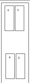
The internal system software designation for storage devices (hard disk drives (HDD) or solid state drives (SSD) is shown in FIGURE 3-4.
FIGURE 3-4 Designation of HDDs or SSD
|
1. Locate and remove the drive filler panels from the server module bays.
For drive locations on the server, see FIGURE 3-4.
For instructions to remove drive filler panels, see Remove or Insert Filler Panels.
2. Ensure that the release lever on the drive is in a fully opened position.
3. Slide the drive into the vacant slot by pressing the middle of the drive faceplate with your thumb or finger.
The release lever will start to close as it makes contact with the chassis.
Do not slide the drive in all the way. Leave the drive out approximately 0.25 to 0.50 inch (6 to 12 mm) from the opening.
FIGURE 3-5 Adding a Drive-Server Not Installed in Chassis
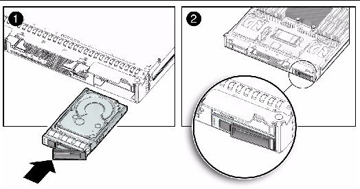
FIGURE 3-6 Adding a Drive-Server Installed in Chassis
4. Using your thumb or finger, press on the middle of the drive’s faceplate until the release lever engages with the chassis.
5. Close the release lever until it clicks into place and is flush with the front of the server.
A single storage device failure does not cause a data failure if the storage devices are configured as a mirrored RAID 1 volume (optional). The storage device can be removed, and when a new storage device is inserted, the contents are automatically rebuilt from the rest of the array with no need to reconfigure the RAID parameters. If the replaced storage drive was configured as a hot-spare, the new HDD is automatically configured as a new hot-spare.
For information about the implementation of RAID on this server and references to RAID controller documentation, refer to the Sun Disk Management Overview For X64 Sun Fire and Sun Blade Series Servers, 820-6350.
|
| Note - This component is a customer replaceable unit (CRU). |
Follow this procedure to replace a HDD or SSD.
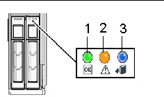
1. Observe the LEDs on the front panel of the drive to verify which drive in the server is faulty.
|
HDD or SSD Service Action Required - amber (faulty disk requiring service) |
|
|
HDD or SSD Ready to Remove - blue (HDD or SSD has been prepared for removal from server) |
2. To remove the faulty drive from the server, perform the following steps:
| Note - The drives are hot-swappable, which means that you can remove them while the server is running. However, you must prepare the operating system on the server before you remove the drives. |
a. Press the release lever button on the drive front panel then tilt the lever into a fully opened position.
FIGURE 3-8 Removing Storage Device-Server Not Installed in Chassis
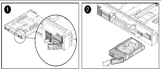
FIGURE 3-9 Removing Storage Device-Server Module Installed in Chassis
b. Hold the opened release lever and gently slide the drive toward you.
c. If you are not immediately replacing the drive, insert a filler panel into the empty drive slot on the server.
For details, see Remove or Insert Filler Panels.

|
Caution - Do not operate the server with empty storage device slots. Always insert a filler panel into an empty storage device slot. For more information, see Remove or Insert Filler Panels. |
3. To install (or replace) the drive, perform the following steps:
a. Ensure that the drive release lever is in a fully opened position.
b. Slide the drive into the vacant slot by pressing the middle of the drive faceplate with your thumb or finger.
The release lever will start to close as it makes contact with the chassis. Do not slide the storage device in all the way. Leave the storage device out approximately 0.25 to 0.50 inch (6 to 12 mm) from the opening.
c. Using your thumb or finger, press on the middle of the drive faceplate until the release lever engages with the chassis.
d. Close the release lever until it clicks into place and is flush with the front of the server.
Follow this procedure when replacing the system battery.
|
| Note - This component is a customer-replaceable unit (CRU). |
Follow this procedure to replace the system battery on the server.
1. Power off the server and remove it from the chassis.

|
Caution - After removing the server from the chassis always insert a filler panel into the empty slot to avoid a possible reduction in system performance. |
2. Remove the cover from the server.
For details, see Remove Cover From Server.
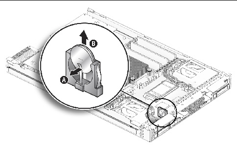
3. To remove the system battery do the following:
a. Using your fingers, unlatch the battery from the socket by twisting the battery away from the socket spring.
b. Lift the battery up and out of the socket, see FIGURE 3-10.
FIGURE 3-10 Removing System Battery
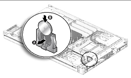
4. Locate the replacement system battery then insert the battery into the socket with the positive (+) side of the battery facing toward the spring, see FIGURE 3-11.
FIGURE 3-11 Inserting System Battery
5. Install the cover on the server.
For instructions, see Install Cover on Server.
The Sun Netra X6270 M2 server module is shipped with standard memory configurations. If you ordered additional memory, a kit for the additional memory is shipped separately.
For details on DIMM considerations, such as DIMM and CPU physical layout, DIMM population rules, DIMM rank classification labels, and error correction and parity, see Appendix D, Memory Module (DIMM) Reference.
|
1. Power off the server and remove the server from the chassis.

|
Caution - After removing the server from the chassis, ensure that a filler panel is inserted into the empty server slot to reduce the possibility of a system shut down. |
2. Remove the cover from the server.
For details, see Remove Cover From Server.
3. To replace a faulty DIMM, perform the following steps; otherwise, proceed to Step 4.
a. Identify the location of the faulty DIMM by pressing the Fault Remind button on the motherboard.
b. To remove the DIMM do the following:
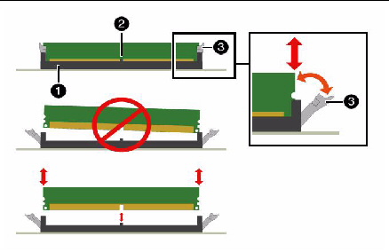
i. Rotate both DIMM slot ejectors outward as far as they will go.
The DIMM is partially ejected from the socket. See FIGURE 3-12.
ii. Carefully lift the DIMM straight up to remove it from the socket.

|
Caution - If you are not immediately inserting a replacement DIMM into the empty DIMM socket, you should insert a DIMM filler panel in the socket. For more details, see Remove or Insert Filler Panels. |
FIGURE 3-12 DIMM Socket Release and Alignment
4. To install a DIMM do the following:
a. Determine the DIMM socket location to populate.
For details, see Appendix D, Memory Module (DIMM) Reference.
| Note - If the DIMM socket contains a filler panel, you will need to remove the DIMM filler panel prior to installing a DIMM into the DIMM socket. For details, see Remove or Insert Filler Panels. |
b. Ensure that the ejector lever at each end of the memory socket are fully open (rotated outward) to accept the new DIMM.
c. Align the DIMM notch to the DIMM connector key. See FIGURE 3-12.
d. Using both thumbs, press the DIMM straight down into the DIMM connector slot until both ejector levers close, locking the DIMM in to the socket.
| Note - The DIMMs must be inserted evenly, straight down into the DIMM connector slot, until the ejector levers lock into place. |
e. Verify that the DIMM ejector levers are upright, seated, and tight. Press on ejector levers to ensure that they are engaged properly.
5. Install the cover on the server.
For instructions, see Install Cover on Server.
The RAID expansion module (REM), if ordered, might not arrive installed on the server module. In some cases, this option is shipped separately for customer installation.
The REM enables the RAID functionality for SAS drives. The server module supports RAID 0, 1, 5 and 6.
Note that when adding a REM to a server, you must install one or more SAS or SATA storage drives (hard disk or solid state drive) in the server disk slots 0 through 3. For further information about the implementation and configuration of RAID on this server, consult the following disk controller documentation:
To install the REM option on the Sun Netra X6270 M2 server module motherboard, refer to the following procedure(s).
|
| Note - The REM SAS cable must be installed when using a REM. For cabling instructions, see Cabling the FEM, REM, and Disk Drives. |
1. Remove the cover from the server.
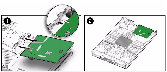
2. Locate the REM support bracket on the motherboard, and slide the REM card at an angle into the support bracket (see FIGURE 3-13 [1]), then press the module carefully into the connector (see FIGURE 3-13 [2]).

|
Caution - The following steps will remove all data from the system. Back up your data to an external site before proceeding. |
3. (Optional) If you want to switch your drives from SATA to SAS (or from SAS to SATA), you should replace the drives at this time.
For details, see Installing or Servicing a Hard Disk Drive or Solid State Drive.
4. Install the cover on the server.
For instructions, see Install Cover on Server.
5. Unless you have preloaded software on the SAS/SATA HDDs or SSDs, your server will not have an operating system, or any data. You will need to restore your data from backups, and install the operating system.
6. Install the cover on the server.
|
| Note - The REM SAS cable must be installed when using a REM. For cabling instructions, see Cabling the FEM, REM, and Disk Drives. |
Follow this procedure to replace or add a REM.
1. Power off the server and remove the server from the chassis.

|
Caution - After removing the server from the chassis, ensure that a filler panel is inserted into the empty server slot to reduce the possibility of a system shut down. |
2. Remove the cover from the server.
For details, see Remove Cover From Server.
3. Remove the existing REM card.
4. Slide the REM card at an angle into the support bracket, then press it carefully into the connector. See FIGURE 3-13.
| Note - For information about the implementation and configuration of RAID on this server, see the Sun Disk Management Document Collection at http://docs.sun.com/app/docs/coll/dsk-mgmt. |
5. Connect the REM to the hard disk drives or solids state drives using the REM SAS cable. See Cabling the FEM, REM, and Disk Drives.
6. Install the cover on the server.
Follow these steps to remove and replace a Fabric Expansion Module (FEM) in a server module.
|
| Note - This component is a customer-replaceable unit (CRU). |
Follow this procedure to add a FEM.
1. Power off the server and remove the server from the chassis.

|
Caution - After removing the server from the chassis insert a filler panel into an empty slot to reduce the possibility of a system shutdown. |
2. Remove the cover from the server.
For details, see Remove Cover From Server.
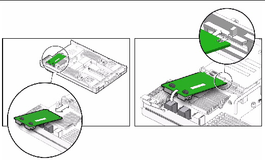
3. Remove the existing FEM card. See FIGURE 3-14.
4. Perform the following steps to install the FEM card:
a. Slide the FEM card at an angle into the support bracket. See FIGURE 3-14.
b. Press the FEM card carefully into the connector. See FIGURE 3-14.
FIGURE 3-14 Removing and Inserting the FEM Card
5. Connect the FEM to the motherboard.
6. Install the cover on the server.
For details, see Install Cover on Server.
The server module is shipped with a preinstalled CPU configuration. If you ordered an alternative CPU assembly option, the optional CPU assembly is shipped separately.
The CPU assembly option contains a CPU chip and a heatsink with preapplied thermal grease. CPU assembly options should only be installed by a qualified Service technician.
Refer to the following procedure when adding a CPU.

|
Caution - The CPU options are field replaceable units (FRUs) and should be installed only by a qualified Service technician. |
1. Remove the cover from the server.
See Remove Server Module From Chassis.
The kit includes a CPU chip and a heatsink with the thermal grease preapplied.
3. Determine the CPU socket location to populate.
4. Remove the air baffle and filler panel from the CPU socket
If you are adding a second CPU to the motherboard for the first time and the CPU is covered by an air baffle, you will need to remove the air baffle and filler panel inside the CPU socket prior to adding the CPU. For instructions, see Remove or Insert Filler Panels.
5. Install the CPU (see FIGURE 3-15).
a. Properly orient the CPU with the socket alignment tabs and carefully place the CPU into the socket.
Ensure that the orientation is correct as damage might result if the CPU pins are not aligned correctly.
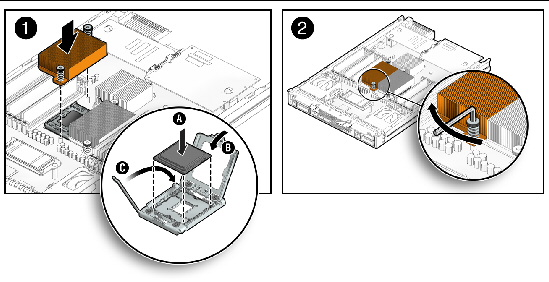
Ensure that the pressure frame sits flat around the periphery of the CPU.
c. Engage the release lever by rotating it downward and slipping it under the catch.
d. Each heatsink has a long-ear tab and a short-ear tab through which the screws attach to mounting studs. See Frame 1 of FIGURE 3-15. To correctly orient the heatsinks, position each long-ear tab closest to the DIMM slots associated with that CPU. The final result will show the heatsinks lined up evenly in the front and rear with silkscreen lines on the motherboard.
e. Carefully position the heatsink on the CPU, aligning it with the mounting posts to reduce movement after it makes initial contact with the layer of thermal grease.

|
Caution - If the heatsink assembly is moved too much during its installation, the layer of thermal grease might not be distributed evenly, leading to component damage. |
f. Tighten the screws alternately one-half turn until fully seated.
6. Install the cover on the server.
|
Follow these steps to replace or upgrade the CPU and Heatsink.
| Note - This component is a field-replaceable unit (FRU) and should be replaced only by qualified Service technicians. Contact your Service representative for assistance. |
1. Power off the server and remove the server from the chassis.

|
Caution - Do not operate the system with empty slots. Always insert a filler panel into an empty slot to reduce the possibility of system shut down. |
2. Remove the cover from the server.
For details, see Remove Cover From Server.
3. To replace a faulty CPU, perform the following steps; otherwise, proceed to
Step 4.
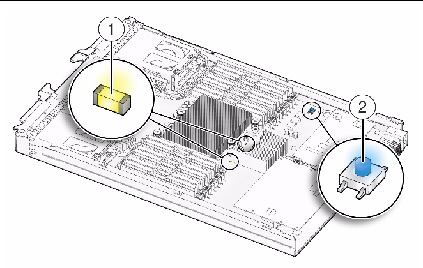
a. Press the Fault Remind button on the motherboard to illuminate the LED for the CPU that has failed. See FIGURE 3-16.
FIGURE 3-16 Fault Remind Button Location
b. To remove the heatsink covering the faulty CPU, perform the following steps:
i. Hold down the top of the heatsink to prevent it from tipping unevenly while you alternately loosen the spring-loaded mounting screws that secure the heatsink to the motherboard.
ii. Using an Allen wrench, turn the screws 180 degrees at a time, and then remove the screws when they are detached. See FIGURE 3-17 [1].
iii. Twist the heatsink slightly to lift it off the motherboard. Turn the heatsink upside down and allow the spring in each of the mounting holes to fall out into your hand.
iv. Clean old thermal grease from existing CPU as soon as the CPU is removed. If you are reinstalling the existing CPU, use an alcohol pad to clean all the old thermal grease from the component surface. Also clean grease from the old CPU chip before removing so as not to contaminate your fingers during removal, which could then lead to further contamination of the newly installed CPU.
FIGURE 3-17 Removing Heatsink and CPU
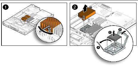
| Note - Set the heatsink upside down on a clean, flat surface to prevent the thermal grease from contaminating other components. |
c. To remove the faulty CPU from the CPU socket, perform the following steps. See FIGURE 3-17 [2].
i. Pivot the socket lever up, into the fully open position.
ii. Open the hinged plate that covers the CPU until it is in the fully open position.
iii. Lift the CPU out of the socket, leaving the lever and plate in the open position.
4. To install (or reinstall) a CPU, perform the following steps.
a. Determine the CPU socket location to populate, then if you are replacing the existing CPU with a new CPU proceed to Step 4b; otherwise, perform one of the following tasks before proceeding to Step 4b:
b. Ensure that the CPU socket release lever and retainer plate are in the fully open position then align the CPU with the CPU socket and gently set the CPU onto the pins in the socket.
| Note - Use the alignment keys in the CPU socket to match the alignment notches on the sides of the CPU. See FIGURE 3-18. |
| Note - Mixing CPU speeds is not supported. Install two identical CPUs in your server. |
FIGURE 3-18 Installing CPU and Heatstink
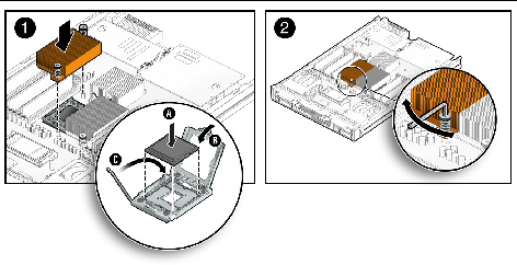
c. When the CPU is fully seated in the socket, pivot the hinged retainer plate down onto the top of the CPU. See FIGURE 3-18 [1].
d. Pivot the release lever down and into the locked position, at the side of the socket.
The release lever must lock down the retainer plate as you close the lever.
5. To install (or reinstall) the heatsink over the CPU socket, perform the following steps.
a. Use the syringe (supplied with the new or replacement CPU) to apply approximately 0.1 ml of thermal grease to the center of the top of the CPU. Do not distribute the grease.
b. Turn the heatsink upright and reinsert the mounting screws. See FIGURE 3-18 [2].

|
Caution - Avoid moving the heatsink after it has contacted the top of the CPU. Too much movement could disturb the layer of thermal grease, leading to component damage. |
c. Carefully position and align the heatsink over the CPU.
| Note - The heatsink is not symmetrical, and it must be aligned with the silkscreen on the PCB before you place it on the CPU. |
d. Lower the heatsink onto the CPU, aligning the mounting screws with their holes on the motherboard.
Each heatsink has a long-ear tab and a short-ear tab through which the screws attach to mounting studs. See Frame 1 of FIGURE 3-15. To correctly orient the heatsinks, position each long-ear tab closest to the DIMM slots associated with that CPU. The final result will show the heatsinks lined up evenly in the front and rear with silkscreen lines on the motherboard.
e. Using an allen wrench, alternately tighten the two heatsink mounting screws, 180 degrees at a time, until each spring is completely compressed.
Tighten the screws to 7 in.-lbs (0.8 Nm).
6. Reinstall the cover on the server.
For details, see Install Cover on Server.
The FEM, REM, and disk drives on the server module require different cabling depending on the option that is chosen. FIGURE 3-19 shows the FEM and the REM installed and cabled directly to the disk drives.
FIGURE 3-19 illustrates cabling paths for the REM (1) and hard drive power (2).
1. Use the REM SAS cable (see cable 1 in FIGURE 3-19) to connect the REM to the hard disk or solid state drives.
| Note - The hard disk drive and solid state drive connect to either the REM or the onboard chipset. |
2. Use the power cables (see cable 3 in FIGURE 3-19) to provide power to the disk drives.
FIGURE 3-19 FEM and REM Cabled Directly to Disk Drives
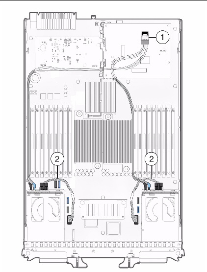
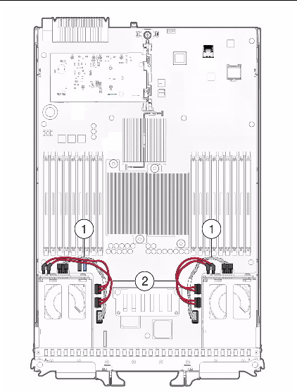
FIGURE 3-20 illustrates the cabling scheme used to connect the disk drives directly to the onboard chipset.
1. Use the ICH10 R SATA cable (see cable 3 in FIGURE 3-20) to connect the HDD or solid state drives to the onboard chipset.

|
Caution - The ICH10 R SATA cable jacks are sized to fit the blue or black onboard connection. Do not force the jacks when making a connection. |
FIGURE 3-20 Disk Drives Cabled Directly to Onboard Chipset
Copyright © 2010, Oracle and/or its affiliates. All rights reserved.