| C H A P T E R 2 |
|
Powering On and Configuring BIOS Settings |
This chapter describes how to power on and off the server, as well as how to configure BIOS settings.
The following topics are discussed in this chapter.
Refer to the following topics in this section to power on and off the server module:
The following procedure assumes that the server module is installed in a powered-on chassis.
1. Verify that the server module is in a standby power state.
In a standby power state, the OK/Power LED on the front panel of the server blinks (0.1 second on, 2.9 seconds off). A standby power state indicates that the server module SP is active but the server module host is powered-off.
See FIGURE 1-1 for the OK/Power LED location.
| Note - The OK/Power LED will be set to standby blink only when there is enough chassis power for the server module to power on. If there is not enough chassis power, the OK/Power LED will remain off until there is enough power for the server module to power on. To troubleshoot this issue, see Troubleshoot Server Power States. |
2. Apply main power to the server SP and host.
For Power button location, see FIGURE 1-1 Front Panel of the Server Module.
The OK/Power LED on the server module front panel illuminates a steady-on green light. The steady-on LED state indicates that the server module SP and host are both powered-on.
If the server does not power-on, see Troubleshoot Server Power States.
Follow these steps to ensure that the server is properly powered off and is ready for removal from chassis.
This operation will cause any Advanced Configuration and Power Interface (ACPI) enabled operating systems to perform an orderly shutdown of the operating system. Servers not running ACPI-enabled operating systems will shut down to standby power mode immediately.
Refer to the Oracle Integrated Lights Out Manager (ILOM) 3.0 Documentation Collection for more information.
2. To ensure that the system is powered off and ready to be removed from the chassis, do the following:
a. Verify that the green OK/Power LED on the front panel of the server is in standby or off state.
b. Ensure that the system was prepared for removal using the Component Management tab in ILOM.
In the Component Management tab, a Ready (no power) status will appear in the Ready To Remove column for the server.
For more details, see the prepare to remove component procedures in the Oracle Integrated Lights Out Manager (ILOM) 3.0 Documentation Collection.
For information about removing the server from the chassis and removing the cover from the server, see Removing the Server From the Chassis.
Each time a server module powers on in the Sun Netra 6000 DC modular system, it queries the CMM to ensure that there is enough power available from the power supply units (PSUs) to power on the server. If there is not enough power to power on the server module, the SP denies the server module from receiving power (standby and main). If this situation occurs, the OK/Power LED on the front panel of the server module will remain off. To troubleshoot this power issue, follow these guidelines:
1. Review the ILOM event log messages to determine whether the server has permission to power on. An event message is recorded in the log any time there is an inadequate amount of power available from the PSUs to power on the server module.
For more information about the ILOM event log or monitoring power consumption, refer to the Oracle Integrated Lights Out Manager (ILOM) 3.0 Documentation Collection.
2. Ensure that the system chassis has the proper amount of power supplies installed to support powering on all the chassis components currently installed.
Refer to the system chassis documentation for information about the number of power supplies required to power on chassis components.
3. To avoid power loss, it is recommended that you use the default CMM power management settings for PSUs in ILOM.
For more information about power management, refer to the Oracle Integrated Lights Out Manager (ILOM) 3.0 Supplement for Sun Netra X6270 M2 Server Module, 821-0943, and the Oracle Integrated Lights Out Manager (ILOM) 3.0 Documentation Collection, 820-5523, 820-6410, 820-6411, 820-6412, 820-6413.
The Basic Input/Output System (BIOS) has a setup utility stored in the BIOS flash memory. The setup utility reports system information and can be used to configure the BIOS settings. The configurable data is provided with context-sensitive help and is stored in the system's battery-backed CMOS RAM. If the configuration stored in the CMOS RAM is invalid, the BIOS settings return to their default optimal values.
There are seven menus in the BIOS Setup Utility, which appear in this order: Main, Advanced, PCI, Boot, Security, Chipset, and Exit. To navigate the menus or options listed on the menu, use the arrow keys. The options or fields that you can configure on a menu appear in color. For further instructions on how to navigate and change settings in the BIOS Setup Utility, refer to the online instructions provided on the menu.
For additional information about the BIOS operations and menu options available on your server, refer to the following sections:
Refer to the following sections for information when booting the BIOS and other
set up considerations:
At system startup, the BIOS performs a power-on self-test that checks the hardware on your server to ensure that all components are present and functioning properly. TABLE 2-1 identifies the events that can occur during BIOS POST, as well as specifies whether these event can prevent the host from powering-on.
|
All installed memory has experienced an unrecoverable failure |
||
Each power-on self-test (POST) diagnostic is a low-level test designed to isolate faults in a specific hardware component. If the POST diagnostics discloses an F1 or F2 error, it typically reports the following information about the error:
TABLE 2-2 lists some of the F1 and F2 error messages that could appear during the POST diagnostics along with instructions for how to possibly resolve the error reported.
The BIOS POST memory testing is performed as follows:
1. The first megabyte of DRAM is tested by the BIOS before the BIOS code is copied from ROM to DRAM.
2. After exiting out of DRAM, the BIOS performs a simple memory test (where a write/read of every location with the pattern 55aa55aa is performed).
| Note - The simple memory test is performed only if Quick Boot is not enabled from the Boot Settings Configuration screen. Enabling Quick Boot causes the BIOS to skip the memory test. |
3. The BIOS polls the memory controllers for both correctable and non-correctable memory errors and logs those errors into the SP.
4. The message, BMC Responding, appears at the end of POST.
The Sun Netra X6270 M2 server module supports up to two chassis PCI Express ExpressModules (PCIe EMs) per server module.
The chassis slots for the PCIe Express Modules are detected by the BIOS during startup in this order: PCIe EM BLn.1 and PCIe EM BLn.0. For example, if the server is in slot 3, the BIOS boot priority is 3.1, 3.0.
See the chassis documentation for further information on PCIe EMs.
The Sun Netra X6270 M2 server module supports up to two 10/100/1000BASE-T Gigabit Ethernet ports provided by the network express modules (NEMs) installed in the chassis. The lower NEM port is NET 0 and the upper NEM port is NET 1, as shown in FIGURE 2-1.
If you have the InfiniBand NEM installed, only one Ethernet port per server module will be available.
FIGURE 2-1 Ethernet Port Chassis Labeling Designations
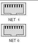
For further information on NEMs, see the chassis documentation.
The device naming for the Ethernet interfaces is reported differently by different interfaces and operating systems.
See TABLE 2-3 for the logical (operating system) and physical (BIOS) naming conventions used for each interface.
|
eth0[1] |
||
|
eth0[2] |
||
|
eth0[3] |
||
|
vmnic#[4] |
The order in which the BIOS detects the Ethernet ports during bootup, and the corresponding drivers that control those ports, are listed below:
TABLE 2-4 provides descriptions for the seven top-level BIOS setup menus.
FIGURE 2-2 identifies the sub-menus that you can access from each of the seven top-level BIOS menus.
FIGURE 2-2 Server Module BIOS Configuration Utility Menu Tree
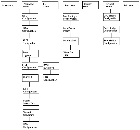
For an example of the options that are available on the BIOS Setup Utility menus, see Appendix B.
This section includes instructions for:
The following procedure describes the steps for accessing the BIOS Setup Utility menus.
1. Power-on or power-cycle the server.
2. To enter the BIOS Setup Utility, press the F2 key while the system is performing the power-on self-test (POST).
| Note - If there is an error during the boot process, you can press F1 to access the BIOS Setup Utility. |
Alternatively, you can also use the following hot key combinations when accessing the BIOS Setup Utility from a serial connection:
The BIOS Setup Utility Main menu appears.
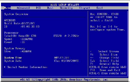
If you intend to use the Trusted Platform Module (TPM) feature set that is provided in Windows 2008, OEL 5, and SLES 11, you must configure the server module to support this feature. For details, see the following procedure.
1. Access the BIOS Setup Utility menus.
For instructions, see Access BIOS Setup Utility Menus.
2. In the BIOS Setup Utility, select the Advanced menu option.
The Advanced Settings screen appears.
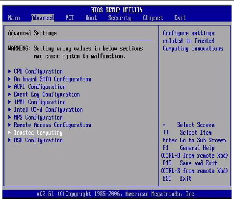
3. In the Advanced Settings screen, select Trusted Computing, then press Enter.
The Trusted Computing screen appears.
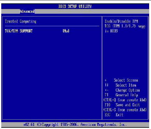
4. In the Trusted Computing screen, select TCG/TPM Support.
A tab appears listing the available TCG/TPM options.
5. Set the TCG/TPM Support option to Yes, then click OK.
| Note - Even if the TCG/TPM Support option is already set to Yes, you should complete the remaining steps in this procedure to ensure that all TPM configuration requirements are satisfied. |
The updated Trusted Computing screen appears, indicating that the TCG/TPM Support setting has changed to Yes.
6. In the Trusted Computing screen, select the Execute TPM Command, then press Enter.
A tab appears listing the available Execute TPM Command options.
7. Set the Execute TPM Command option to Enabled, then click OK.
The updated Trusted Computing screen appears, indicating that the Execute TPM Command setting has changed to Enabled.
8. Press F10 to save the changes and exit BIOS.
9. To verify that TPM support is enabled, do the following:
a. Reboot the server then access the BIOS Setup Utility by pressing F2 key.
The BIOS Setup Utility Main menu appears.
b. In the BIOS Setup Utility, select Advanced --> Trusted Computing, then press Enter.
The updated Trusted Computing screen appears indicating that TPM Support is set to Yes and TPM Enable Status is set to Enabled.
You can assign an IP address for the server SP from the BIOS Setup Utility on the IPMI LAN configuration menu. Alternatively, you can also specify the LAN settings for the SP using ILOM. For instructions for setting the IP address in ILOM, see the Oracle Integrated Lights Out Manager (ILOM) 3.0 Documentation Collection.
To set the IP address in the BIOS Setup Utility, use the menus to navigate to the LAN configuration setting as follows: Advanced --> IPMI Configuration --> LAN Configuration. See FIGURE 2-2 for menu navigation tree.
1. Access the BIOS Setup Utility menus.
For instructions, see Access BIOS Setup Utility Menus.
2. In the BIOS Setup Utility menus, use the arrow keys (or Tab key) to navigate to the Advanced menu.
3. In the Advanced menu, select IPMI 2.0Configuration.
4. In the IPMI Configuration menu, select LAN Configuration.
5. In the LAN Configuration settings screen, use the arrow keys to select and specify the appropriate LAN configuration settings.
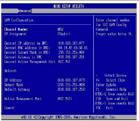
6. Press F10 to save the changes and exit BIOS.
The BIOS Option ROM is 128 Kbytes. Of these 128 Kbytes, approximately 80 Kbytes are used by the VGA controller, the disk controller, and the network interface card. Approximately 48 Kbytes remain for the Option ROM.
1. Access the BIOS Setup Utility menus.
For instructions, see Access BIOS Setup Utility Menus.
2. In the BIOS Setup Utility menus, use the arrow keys or Tab key to navigate to the Boot menu.
3. In the Boot menu, highlight the Option ROM setting, then press Enter.
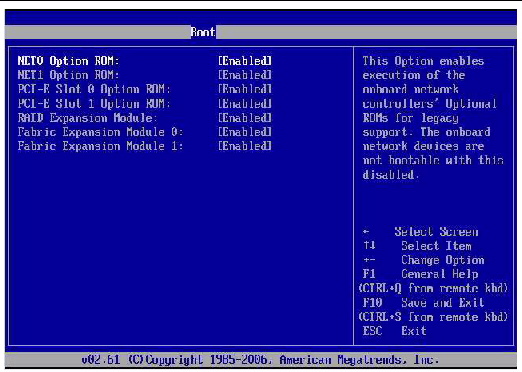
4. In the Boot menu listing the Option ROM settings, highlight the applicable Option ROM setting to modify, then press Enter.
A tab appears listing the available settings.
5. In the tab, do one of the following:
6. Press F10 to save the changes and exit BIOS.
The BIOS is updated whenever you update the ILOM SP firmware. For instructions about updating the firmware, refer to the Oracle Integrated Lights Out Manager (ILOM) 3.0 Documentation Collection.
Copyright © 2010, Oracle and/or its affiliates. All rights reserved.