| C H A P T E R 6 |
|
Sending Events From the RFID Event Manager to the RFID Information Server |
The easiest way to send the RFID tag events from the RFID Event Manager to a database is to use the Epcis connector (a component of the RFID Event Manager), the RFID Information Server (also known as EPCIS), and an application server. There are other ways to accomplish this task, but they require more programming.
The Epcis connector can be used with two protocols: the Java Message Service (JMS) API and HTTP. The resulting connectors are called the EpcisHttp connector and the EpcisJms connector.
This chapter includes the following topics:
The following software must be installed and properly configured before you can use the procedures in this chapter.
Sun Java System Application Server 8.1 (Application Server) provides support for applications that use the Java Message Service (JMS) application programming interface (API) for messaging operations. JMS is a set of programming interfaces that provide a common way for Java applications to create, send, receive, and read messages in a distributed environment. JMS is a standard way that Java 2 Platform, Enterprise Edition (J2EE platform) applications perform asynchronous messaging. J2EE components, web components or Enterprise JavaBeans
 (EJB
(EJB ) components - can use the JMS API to send messages that can be consumed asynchronously by a specialized EJB, called a Message Driven Bean (MDB).
An MDB is similar to a session bean, except it responds to a JMS message rather than an RMI event. MDBs were introduced in the EJB 2.0 specification. The MDB represents the integration of JMS (Java Message Service) with the EJB software to create an entirely new type of bean designed to handle asynchronous JMS messages.
Application Server support for JMS messaging and for MDBs, requires messaging middleware, a JMS provider, that implements the JMS specification. Application Server uses Sun Java System Message Queue 3 2005Q1 (Message Queue) as its native JMS provider. The Sun Java System RFID Information Server installer creates the following JMS resources on the application server:
RFID Information Server clients can be configured to use the JMS interface using a file system JNDI provider (Java Naming and Directory Interface).
This section include the following topics:
The Sun Java System Message Queue 3 2005Q4 Administration Guide can be found at http://docs.sun.com/app/docs/doc/819-2571.
The complete documentation set for Sun Java System Message Queue 3 2005Q4 can be found at http://docs.sun.com/app/docs/coll/1307.1.
The RFID Information Server installer creates the necessary JMS resources on the Application Server. You need to configure the Java Naming and Directory Interface (JNDI) File System Provider object store.
See Sun Java System Application Server Platform Edition 8.1 2005Q2 Update 2 Administration Guide found at http://docs.sun.com/app/docs/doc/819-2641 for more information on configuring JMS Resources and understanding JNDI resources. It is not the intent of this guide to fully explain these topics. The following illustration shows how the RFID Event Manager queries the JNDI repository to determine the physical parameters necessary for using the JMS messaging protocol.
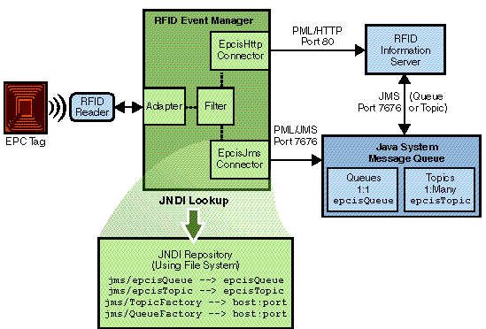
The procedures in this chapter show screen captures using Application Server Platform Edition on a Windows system. Using the Application Server and Message Queue GUI interfaces on other platforms may differ slightly in appearance.
Perform the following procedures in the order they are presented:
|
The RFID Information Server installer creates JMS resources for you. This procedure describes how to view and confirm that these resources were successfully created.
1. Start the application server default server instance.
2. Log in to the application server admin console.
3. Choose Resources  JMS Resources
  Connection Factories.
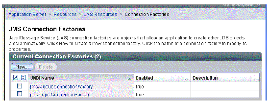
Confirm that the jms/QueueConnectionFactory and jsm/TopicConnectionFactory nodes are present as shown in the following screen capture.
4. Choose Resources  JMS Resources
  Destination Resources nodes.
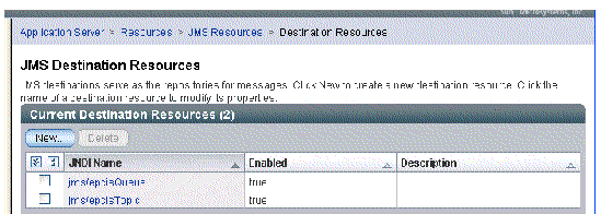
Confirm that the jms/epcisTopic and jsm/epcisQueue nodes are present as shown in the following screen capture.
|
You need to a add a broker that points to your local JMS Message Queue server, or whichever Message Queue server you want to use.
|
Note - This example uses the Sun Java System Message Queue that is installed as part of the Sun Java System Application Server 8.1 installation. |
1. Start the Message Queue admin console.
These examples use the default Application Server installation directory for each platform.
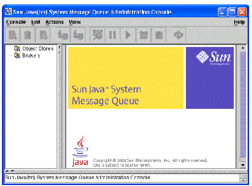
2. Select the Brokers node in the navigation tree.
3. From the menu, choose Actions  Add Broker.
The Add Broker dialog box appears.
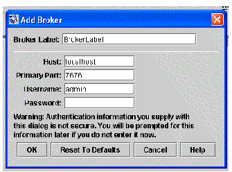
4. Add a new broker by following these steps:
a. In the Broker Label field, type a name for your broker.
For this example, type TestRFIDBroker.
a. In the Host field, type the IP address of the machine where your Message Queue server is installed.
In this example, this is the system where Application Server is installed.
b. In the Primary Port field, confirm the default value of 7676.
c. Type the Message Queue admin username and password.
The admin username and password is admin.
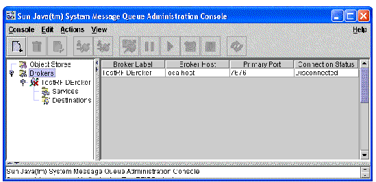
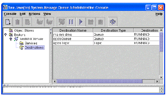
5. Right-click the new Broker icon in the navigation tree and choose Connect to Broker.
For this example, right-click TestRFIDBroker. The destinations match the destinations that you viewed in the Application Server JMS Resources.
|
From the Message Queue admin console, add a new Object Store by following these steps:
1. Select the Object Stores node in the navigation tree.
2. From the menu, choose Actions  Add Object Store.
The Add Object Store dialog box appears and enables you to add the necessary JNDI Naming Server Properties. The following screen capture shows the JNDI Naming Server Properties drop-down list.
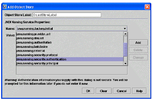
|
password for the user specified in java.naming.security.principal |
4. In the Object Store Label field, type a name for this object store.
For this example, type EpcisObjectStore.
The new Object Store appears in the navigation tree.
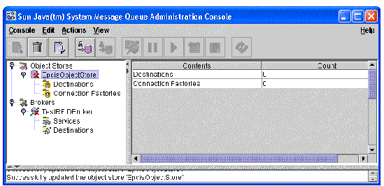
6. Right-click the new Object Store node in the navigation tree and choose Connect to Object Store.
You should see a successful connection.
|
From the Message Queue admin console, add a new connection factory for the epcisTopic by following these steps:
1. Select the Connection Factories node in the navigation tree.
2. From the menu, choose Actions  Add Connection Factory Object.
The Add Connection Factory Object dialog box appears.
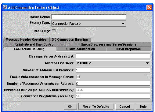
For this example, use TopicConnectionFactory.
4. In the Factory Type field, select TopicConnectionFactory from the drop-down list.
5. Select the 3.0 Connection Handling tab and complete the fields as shown in the following screen capture.
In the fields, Broker Host Name and HTTP URL, replace localhost with the name of the machine where your Message Queue broker resides.
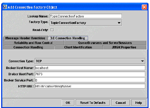
The topic connection factory object is added to the object store.
|
1. Select the Connection Factories node in the navigation tree.
2. From the menu, choose Actions  Add Connection Factory Object.
The Add Connection Factory Object dialog box appears.
For this example, use QueueConnectionFactory.
4. In the Factory Type field, select QueueConnectionFactory from the drop-down list.
5. Select the 3.0 Connection Handling tab and complete the fields as shown in the following screen capture.
In the fields, Broker Host Name and HTTP URL, replace localhost with the name of the machine where your Message Queue broker resides.
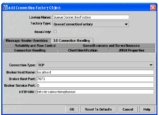
The new queue connection factory object is added to the object store.
|
1. Select the Destinations node in the navigation tree.
2. From the menu, choose Actions  Add Destination Object.
The Add Destination Object dialog box appears.
3. Add both a topic and a queue destination object as shown in the following screen captures.
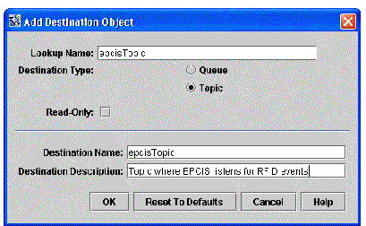
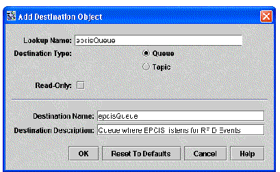
4. Confirm that your new object store appears similar to the following screen capture.
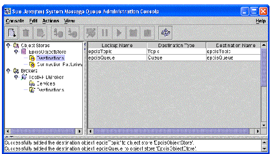
5. When you are finished, exit the Message Queue Admin Console.
You have completed the JMS configuration for your system. Now, you must configure the RFID Event Manager to send the tag events to the RFID Information Server. See Configuring the RFID Event Manager to Use an EpcisJms Connector.
The following procedures use the RFID Configuration Manager, a component of the RFID Event Manager. If you are unfamiliar with this component, review Chapter 2 to familiarize yourself with the GUI terminology and functionality before proceeding.
Prerequisite - Be sure that you have reviewed Enabling Usage of JMS With the RFID Information Server and enabled JMS before starting this procedure.
Perform the following procedures:
|
Use these steps to define a new role that uses the EpcisJms connector. A role specifies a series of filters and connectors that receive tag events and pass them to a listener application. In this example, the Westerner is the RFID Information Server.
Roles are described in Chapter 2 of this guide. Review To Define RFID Event Manager Roles if you have not used the RFID Configuration Manager previously.
Prerequisite - You must create your JNDI object store before performing this procedure. See Enabling Usage of JMS With the RFID Information Server.
1. Start the RFID Configuration Manager.
The location of the start script depends on your platform:
 Choose Start
  Programs
  Sun Microsystems
  Sun Java System RFID Software
  Configuration Manager.
The Select a Role dialog appears.
3. Type the new role name and click Ok.
For this example, type JMS Message for IS. The drawing pane appears.
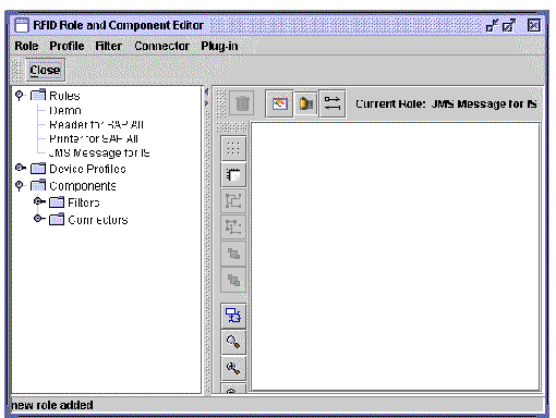
4. Click the Add a connector icon (looks like a roll of film) and select EpcisJms from the list.
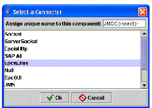
For the example, type JMSConnector. The Epcis connector named JMSConnector appears in the drawing pane.
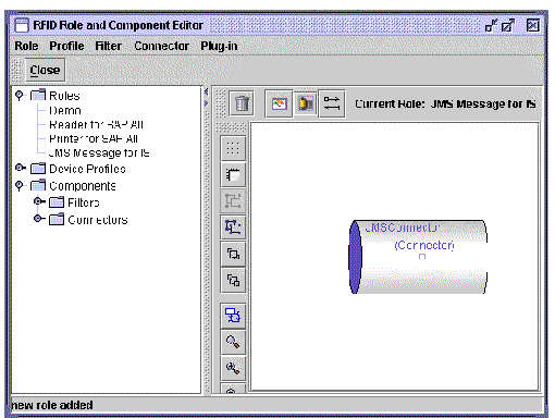
6. Right-click the connector (move the cursor over the small square at the center of the Connector symbol) and select Edit.
The Connector Details dialog appears.
7. Confirm that the Configuration Properties fields contain the correct values for your JMS configuration and click OK.
The values of the java.naming properties must match the values in your JNDI object store as shown in the following table.
|
tester (the user name that you specified for connecting to the RFID Information Server) |
|
|
password for the user specified in java.naming.security.principal |
|
8. Add a Delta filter by using the Add a filter icon (looks like a meter).
You must use a Delta filter to feed the tag events to the EpcisJms connector. If you do not add the Delta filter to this role, the tag events are ignored by the connector.
9. Type a name for your Delta filter and click OK.
10. Add a Smoothing filter by using the Add a filter icon (looks like a meter).
11. Type a name for your Smoothing filter and click OK.
The drawing pane appears similar to the following screen capture.
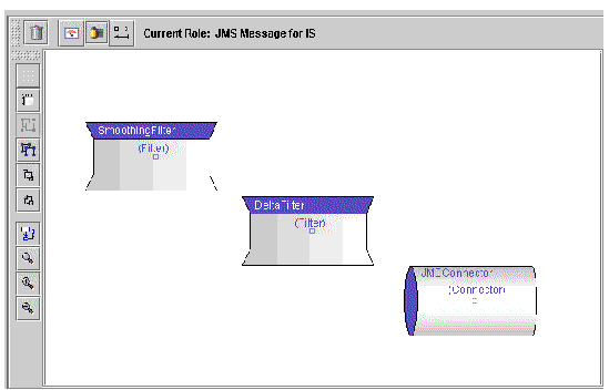
12. Right-click on the Smoothing filter and select Create Input from the popup menu.
A new input object appears on the drawing pane.
13. To connect everything together, click the port (small square) at the center of the input and drag it to the Smoothing filter.
14. Click the port of the Smoothing filter and drag it to the Delta filter.
15. Click the port of the Delta filter and drag it to the JMSConnector.
16. Click on the Auto-Layout icon to arrange the components vertically on the drawing pane.
This enables you to see how the tag events flow through this role.
|
Note - The drawing pane icons are described in TABLE 2-1. |
Your drawing pane appears similar to the following screen capture.
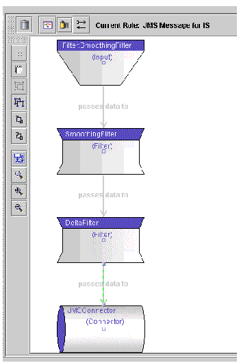
Your work is not yet saved. To save your work at this time, choose File  Save from the RFID Configuration Manager main menu.
18. You must complete the following procedure to configure the EpcisJMS configuration object.
|
The Select the Base Role dialog box appears.
2. Select the role, JMS Message for IS, that you defined in the previous procedure and click OK.
The Configuration Object properties dialog appears. Notice that there are three tabs corresponding to the components that you defined in the JMS Message for IS role.
3. Type a name in the Configuration Object Name field.
For this example, type JMSConfigObject.
4. To configure the input point for the configuration object, select a reader by following these steps:
b. (For demonstration or verification purposes) Select PMLReader.
When you select the reader, the configuration properties for that reader profile appear.
c. (If using a real reader, rather than the PMLReader) Select your reader and confirm that the reader properties correspond to the reader you are using.
When defining the EpcisJms connector in a real-world situation, you would define your readers (devices) first. Then, when you define your configuration objects, the list of possible input points would display all your defined readers (devices). See Chapter 2 for more information.
6. If the drawing pane displays the default Demo configuration object, delete it following these steps.
a. Select the Demo configuration object.
b. Choose Configuration  Delete.
7. Choose File > Save to save your changes and click OK when prompted.
8. (Optional) To exit the RFID Configuration Manager, choose File  Exit.
Exit.
9. (Optional) To test the EpcisJms connector, perform the next procedure To Test the EpcisJms Connector.
|
1. Start or restart your application server.
2. Start or restart the RFID Event Manager.
Each time you change a configuration object, the RFID Event Manager must be restarted in order for the changes to take effect. Wait until the system is completely started or you may lose tag events. Depending on the components you used in your role, the RFID Tag Viewer may or may not appear (it depends on the objects in your role). The delay lets the system come up completely before generating EPC tags.
4. Start the RFID Tag Viewer from the command line using the following options.
You should see tags appearing in the RFID Tag Viewer.
5. After a few seconds, you can stop the PML Reader.
6. (Optional) To verify that events are flowing from the RFID Event Manager to the RFID Information Server, follow these steps:
a. In your web browser, access the RFID Information Server index page by typing the EPCIS URL.
For example, http://localhost/epcis.
b. Select Epcis Reporting Framework  Epcis Tables.
Scroll down to the OBSERVATION_LOG table.
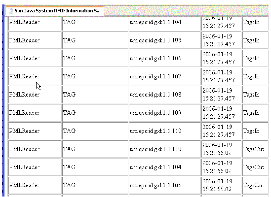
The TagsIn and TagsOut that have been added to the OBSERVATION_LOG table indicate that tags were read and were taken out of view from the RFID Event Manager. You should see something similar to the following screen capture.
To use HTTP to communicate with the RFID Information Server, use an EpcisHttp connector. The tasks for configuring an EpcisHttp connector are similar to configuring a EpcisJms connector, except you do not need to do the JMS configuration. Perform the following procedures:
|
1. Start the RFID Configuration Manager.
The Select a Role dialog appears.
3. Type the new role name and click Ok.
For this example, type testEpcisHttpRole.
4. Click the Add a connector icon (looks like a roll of film) and select EpcisHttp from the list.
6. To edit/confirm the properties, right-click the connector and choose Edit.
Move the cursor over the port (the small square at the center of the connector object). The Connector Details dialog box appears.
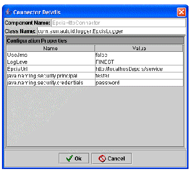
7. Confirm that the properties contain the correct values, and click OK.
8. Add a Smoothing filter and a Delta filter.
See Step 8 through Step 11 in To Define the EpcisJms Connector Role.
9. Right-click the Smoothing filter and choose Create Input from the context menu.
10. To connect everything together, click the port (small square) at the center of the input and drag it to the Smoothing filter.
11. Click the port of the Smoothing filter and drag it to the Delta filter.
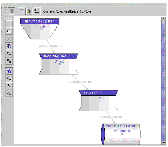
12. Click the port of the Delta filter and drag it to the EpcisHttpConnector.
13. Drag the components to arrange them on the drawing pane as needed or click on the Auto-Layout icon to arrange the components vertically.
This enables you to see how the tag events flow through the role.
|
Note - The drawing pane icons are described in TABLE 2-1. |
Your drawing pane appears similar to the following screen capture.
14. Click close and proceed to the next procedure,
Your work is not yet saved. Do not exit the RFID Configuration Manager without saving your work.
|
1. Start the RFID Configuration Manager.
2. If the drawing pane displays the default Demo configuration object, delete it following these steps.
a. Select the Demo configuration object.
b. Choose Configuration  Delete.
The Select the Base Role dialog box appears.
4. For this example, select the role, testEpcisHttpRole, that you defined in the previous procedure and click OK.
The Configuration Object properties dialog appears. Notice that there are three tabs corresponding to the components that you defined in the role.
5. Type a name in the Configuration Object Name field.
For this example, type HTTPConfigObject.
6. To configure the input point for the configuration object, select a reader by following these steps:
b. (For demonstration or verification purposes) Select PMLReader.
When you select the reader, the configuration properties for that reader profile appear.
c. (If using a real reader, rather than the PMLReader) Select your reader and confirm that the reader properties correspond to the reader you are using.
When defining the EpcisHttp connector in a real-world situation, you would define your readers (devices) first. Then, when you define your configuration objects, the list of possible input points would display all your defined readers (devices). See Chapter 2 for more information.
8. Choose File > Save to save your changes and click OK when prompted.
9. (Optional) To exit the RFID Configuration Manager, choose File  Exit.
Exit.
10. (Optional) To test the EpcisHttp connector, perform the next procedure
|
1. Start or restart the RFID Event Manager.
Each time you change a configuration object, the RFID Event Manager must be restarted in order for the changes to take effect.
Wait until the system is completely started or you may lose tag events. Depending on the components you used in your role, the RFID Tag Viewer may or may not appear (it depends on the objects in your role). The delay lets the system come up completely before generating EPC tags.
3. Start the RFID Tag Viewer from the command line using the following options.
You should see tags appearing in the RFID Tag Viewer.
4. After a few seconds, you can stop the PML Reader.
5. (Optional) To verify that events are flowing from the RFID Event Manager to the RFID Information Server, follow these steps:
a. In your web browser, access the RFID Information Server index page by typing the EPCIS URL.
For example, http://localhost/epcis.
b. Select Epcis Reporting Framework  Epcis Tables.
Scroll down to the OBSERVATION_LOG table.
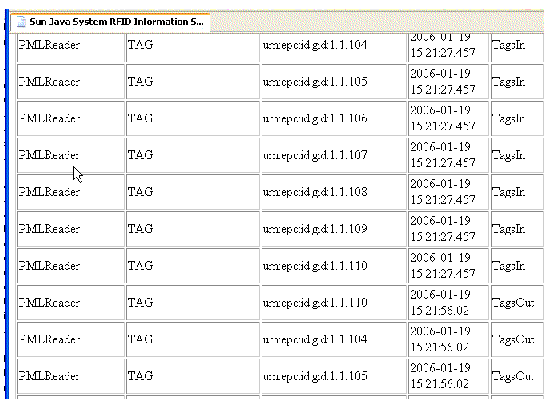
The TagsIn and TagsOut that have been added to the OBSERVATION_LOG table indicate that tags were read and were taken out of view from the RFID Event Manager. You should see something similar to the following screen capture.
Copyright © 2006, Sun Microsystems, Inc. All Rights Reserved.