| Netra CP3010 Board User's Guide
|
   
|
Introduction to the Netra CP3010 Board
|
This chapter contains the following sections:
1.1 Overview of the Netra CP3010 Board
The Netra CP3010 board is a high-performance single-board computer based on two UltraSPARC® IIIi processors and designed for high availability in a switched network computing environment. This board is compliant with Advanced Telecom Computing Architecture® (ATCA) specifications (PICMG® 3.0 and PICMG 3.1) and can achieve greater performance levels than compactPCI (cPCI) standards-based products targeted for telco markets.
The PICMG (PCI Industrial Computer Manufacturers Group) standards committee has developed the new standard ATCA (or PICMG 3.x) to address the issues posed by previous standards based on cPCI and cPSB (PICMG 2.x). The PICMG 3.x specification brought the following changes to the existing PICMG 2.x family of products:
- Larger board space (8U high compared to 6U for cPCI), which allows more features and processing power
- On-board power supplies deriving local power from redundant -48V power from the midplane (rather than separate power supplies)
- 6 HP slot width, allowing greater component height and new PCI Mezzanine card (PMC) options
- Elimination of PCI connectivity between the boards in the system and reallocation of connectivity to serial interconnects, eliminating single points of failure in the system
- Mandatory use of Intelligent Platform Management Interface (IPMI) management interfaces
- Flexible user I/O
- Power and thermal management guidelines enforced by the management infrastructure
- Separation of control and data traffic by supporting Base Fabric (PICMG 3.0) and Extended Fabric (PICMG 3.1) interfaces
The ATCA standard consists of the PICMG 3.0, PICMG 3.1, PICMG 3.2, and PICMG 3.3 specifications. The Netra CP3010 board complies with:
- PICMG 3.0, the base specification that defines the mechanical, power distribution, system management, data transport, and regulatory guidelines
- PICMG 3.1, which builds upon the PICMG 3.0 base specification and the IEEE 802.3-2003 standard
1.2 Features of the Netra CP3010 Board
The Netra CP3010 board provides two 10/100BASE-T Ethernet interfaces for the Base Fabric interface (a requirement of PICMG 3.0) and two serializer, deserializer (SERDES) gigabit Ethernet interfaces (PICMG 3.1) for the Extended Fabric interface. The Base Fabric interface is used as the control interface and the Extended Fabric interface can be used for data traffic. Both Base Fabric and Extended Fabric interfaces are configured as Dual Star configurations.
Netra CP3010 board features include:
- Single or dual UltraSPARC IIIi+ processors
- DDR-1 memory, up to 8 Gbytes (Very Low Profile DIMMs)
- JBus-PCI ASICs (application-specific integrated circuits) to bridge processors and the PCI I/O subsystem
- Two PCI Mezzanine card (PMC) expansion slots that support PCI I/O expansion and storage PMC modules
- Two-channel Serial Attached SCSI (SAS) port for external storage access (2X front and rear)
- Two 10/100BASE-T Ethernet interfaces as maintenance ports
- Two asynchronous serial ports
- Compact Flash socket to support a 1-Gbyte or 2-Gbyte user flash type I memory card
- Management support using Pigeon Point Systems Intelligent Platform Management (IPM) controller, providing a redundant IPMI channel to communicate with the ATCA shelf manager
- Rear I/O access using a compatible rear transition card (RTC)
FIGURE 1-1 shows the Netra CP3010 board and front panel.
FIGURE 1-1 Dual Processor Netra CP3010 Board (Front View)
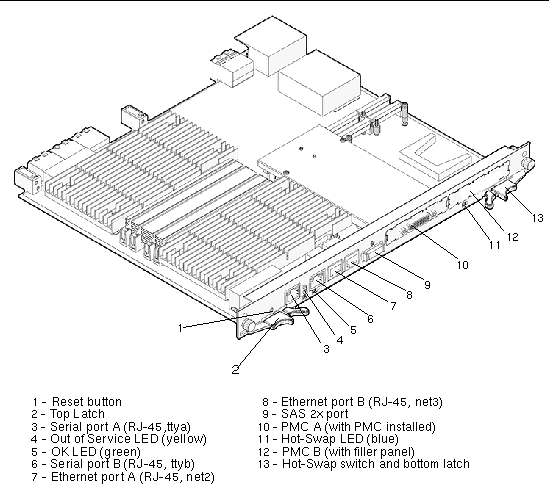
FIGURE 1-2 shows the component veiw of the Netra CP3010 board.
FIGURE 1-2 Netra CP3010 Board (Top View)
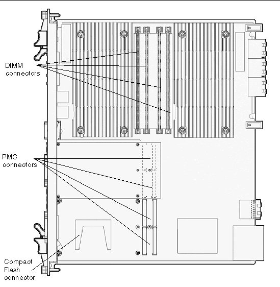
TABLE 1-1 lists features of the board.
TABLE 1-1 Feature Summary for the Netra CP3010 Board
|
Feature
|
Description
|
|
CPU
|
- Two UltraSPARC IIIi processors
- CPU core speed: 1.0 GHz
- Both processors operate at the same speed
|
|
Memory
|
- Four DDR-1 184-pin Very Low Profile (VLP) DIMMs, buffered, registered
- 1-Gbyte or 2-Gbyte DIMMs, for a total memory of 4 or 8 Gbytes for two CPU configurations
- ECC supported
|
|
Power requirement
|
ATCA 3.0 standard of 200 watts maximum
|
|
PICMG and PMC compliance
|
- PICMG 3.0 R1.0
- PICMG 3.1 R1.0
- PCI Mezzanine Card (PMC) IEEE P1386.1/Draft 2.3
- PICMG 2.15 R1.0 (PCI Telecom Mezzanine/Carrier Card [PTMC] standard)
|
|
Node board support
|
The board functions as a CPU node board with the Solaris software package
|
|
Operating system
|
Solaris 10 OS
Solaris 9 9/05 OS and subsequent compatible versions with supported Netra patches
|
|
Internal I/O (connections to ATCA midplane)
|
- Dual gigabit Ethernet for Base Fabric interface
- Dual SERDES interface as Extended Fabric interface
- Dual IPMI channel connects to the midplane for communicating with the Shelf Management card
|
|
External I/O
|
- Two 10/100 Mbps Ethernet ports for maintenance (front or rear)
- Two asynchronous serial ports (front and rear)
- Dual 2X SAS ports (one front and one rear), speed: 300 Mbps per channel
- Rear access support using Netra CP30X0 rear transition card:
- CP3010 front I/O is redirected to rear when RTC is present.
- Serial port access is available in front and rear when RTC is present. It is available only in front when no RTC is present.
- 2X SAS port is available in front and rear (RTC required) at all times.
- PMC I/O rear access requires corresponding PIMs:
- Majority of PMC I/O is routed to RTC as single-ended signals.
- Others are routed as differential pairs to support certain Fibre Channel PMC cards.
|
|
IPMI system management
|
Uses IPMI communications with baseboard management controller (BMC); performs advanced system monitoring (ASM) on local board interface (for example, temperature sense, FRU ID, and control)
|
|
Hot-swap support
|
Basic, full, and high-availability (HA) hot-swap support
|
|
Front panel access
|
- Two serial ports (SubDB-9)
- Two 10/100BASE-T Ethernet ports (RJ-45)
- Two PMC I/O access panels
- One 2X SAS port (via 4X external SAS connector)
- Recessed reset push button
|
|
PMC I/O
|
Provision for adding up to two independent hardware vendor (IHV) supplied PMC expansion ports on front panel
|
|
NVRAM
|
8-Kbyte nonvolatile inter-integrated circuit (I2C) serial EEPROM to save OpenBoot PROM configuration. PROM configuration.
|
|
System flash
|
2 Mbytes on board
|
|
User flash
|
14 Mbytes on board
|
|
Building compliance
|
Network Equipment Building Systems (NEBS) Level 3
|
|
Flash update
|
Supported from downloaded file
|
|
Note - For EMI compliance of front access ports, use shielded cables on all I/O ports. The shields for all shielded cables must be terminated on both ends.
|
1.3 Netra CP3010 Board System Configurations
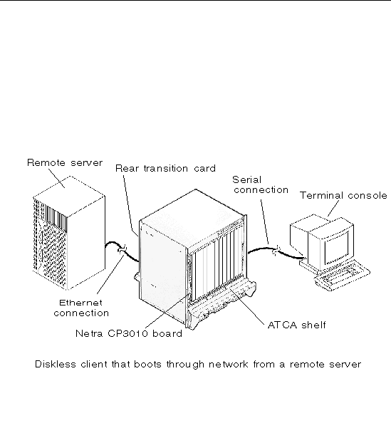
Netra CP3010 boards can be installed in an ATCA shelf (or chassis), shown in FIGURE 1-3. The boards can be deployed in various electrical configurations to suit each end-user requirement. For example, the board can be configured to boot from a network as a diskless client with either a front panel or rear transition card network connection, or from an optional Compact Flash card. Alternatively, industry-standard PCI Mezzanine card (PMC) and PCI Interface Module (PIM) hardware from IHVs can be installed to provide local disk I/O, which can be used optionally as a boot path. The Netra CP3010 board has fixed on-board memory and connectors for additional memory.
FIGURE 1-3 Netra CP3010 Board in an ATCA Shelf Enclosure
1.3.1 PMC and PIM Modules
The Netra CP3010 board has two PMC slots to provide additional I/O to the front panels or to the rear of the enclosure when used with a rear transition card. PMC modules decode their custom I/O from the Netra CP3010 board's on-board PCI bus A signals. A rear transition card can also be fitted with PIMs to bring I/O channels to the rear of the unit. See Section A.6.2, PMC Connectors for more information.
1.3.2 Rear Transition Card
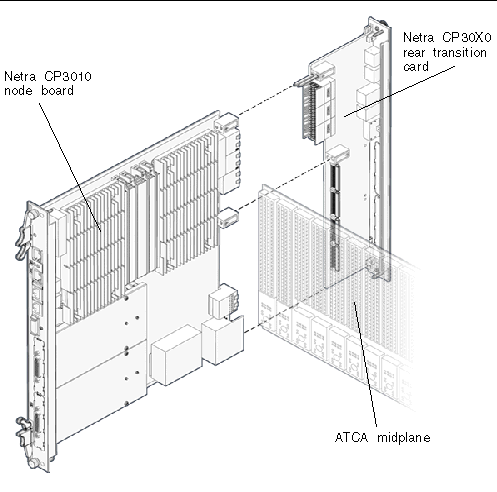
The optional Netra CP30X0 rear transition card installs into the rear of the ATCA enclosure, opposite the Netra CP3010 board (see FIGURE 1-5). The card connects with the host Zone 3 rear I/O connectors and carries two serial ports, two Dual gigabit Ethernet (GbE) ports with RJ-45 connectors, and a two-channel SAS port to its rear-panel flange (see FIGURE 1-4).
FIGURE 1-4 Netra CP30X0 Rear Transition Card
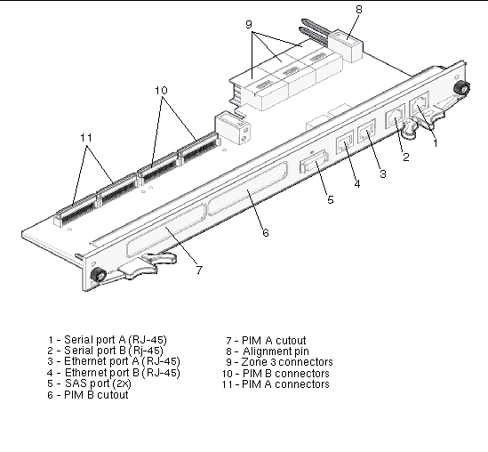
FIGURE 1-5 shows the physical relationship between the board, rear transition card, and the midplane in a typical ATCA system.
FIGURE 1-5 Relationship of the Netra CP3010 Board, Midplane, and Rear Transition Card
|
Note - When the rear transition card is used with the Netra CP3010 board, shielded cables are required for serial I/O ports. Unshielded cables can be used on Ethernet ports to satisfy EMI compliance standards. The shields for all shielded cables must be terminated on both ends.
|
The rear transition card can also be fitted with PIM modules that are configured to bring I/O channels to the unit's rear panel. A PIM hardware kit includes a card for the PMC slot and a card for the PIM slot on the rear transition card. A PIM is a rear-panel extension added to a PMC module. When the PIM I/O is configured, the front PMC I/O output is not accessible.
The customer can order the Netra CP30X0 rear transition card, build a custom card, or buy from an IHV. A minimal set of I/O must provide a boot path for the host board and a path for console I/O to deliver commands and to read board and system status.
Possible boot and console configurations are described in TABLE 1-2. Sun Microsystems provides the Netra CP3010 board and a compatible Netra CP30X0 rear transition card. This card provides two 10/100BASE-T Ethernet RJ-45 ports from the host to the rear of the system, which can optionally be used to accomplish a network boot as a diskless client. The other configurations require IHV hardware.
TABLE 1-2 I/O Configurations
|
I/O
|
Hardware Required
|
Description
|
|
Ethernet
|
Netra CP30X0 rear transition card--supplied as an option for rear access
|
Default boot path uses the Ethernet port; the board runs in diskless client configuration.
|
|
SCSI
|
Netra CP30X0 rear transition card; PMC SCSI I/O
|
SCSI devices can be used for local booting; requires optional rear transition card with PMC SCSI I/O.
|
|
Serial data
|
Netra CP3010 board
Netra CP30X0 rear transition card
|
Serial ports on front panel provide a path for a console I/O.
Both serial ports can be used on either the CP3010 board or CP30X0 transition card, but the same port should not be used on both. If serial port A is used on the CP3010 board, serial port A on the CP30X0 rear transition card should not be used.
|
|
Compact Flash
|
Sun Compact Flash card
|
The Compact Flash connector can be used to add an optional 1-or 2-Gbyte user flash type I memory card.
|
1.4 Hot-Swap Support
This section briefly discusses the hot-swap support on the Netra CP3010 board.
See the PICMG CompactPCI Hot Swap Specification, which provides a detailed description of this subject. In general, the hot-swap process includes the orderly connection of the hardware and software.
This process uses hardware connection control to connect the hardware in an orderly sequence. The process includes the use of backplane pins of different lengths to accomplish signal sequencing, protect the hardware, and avoid corrupting the backplane bus.
There are three hot-swap models described in the PICMG CompactPCI Hot Swap Specification: basic hot-swap, full hot-swap, and high-availability (HA) hot-swap.
1.5 System Requirements
This section contains the system-level hardware and software requirements for the Netra CP3010 board.
1.5.1 Hardware Requirements
Sun provides the following items for customer order:
- Netra CP3010 node board
- Netra CP30X0 rear transition card (optional)
The rear transition card enables rear system I/O access to the network, to a boot device, and to a console terminal (shown in FIGURE 1-4). Refer to the Netra CP30X0 Rear Transition Card User's Guide (819-1187) for more information.
This rear transition card is optional and must be ordered separately from the Netra CP3010 board.
- Compact Flash card (optional)
An IDE Compact Flash card is optional and must be ordered separately.
Acquire the following components, if needed:
- Serial terminal or terminal emulation for console output.
- Cables for terminal and network connections.
- Rear transition cards and PMCs are optional. If a PMC is used, PIM and PMC hardware is needed.
- TOD battery is optional. If used, the battery must be type CR 1632, with a minimum of 4ma abnormal charging current rating (for example; a Panasonic CR 1632).
TABLE 1-3 lists ATCA and other minimum requirements met by the Netra CP3010 board.
TABLE 1-3 ATCA and Other Minimum Requirements Met By the Netra CP3010 Board
|
Requirements
|
Netra CP3010 as Node Board
|
|
ATCA system enclosure for 8U boards (includes chassis, backplane, power supply)
|
Yes
|
|
Console output device or serial terminal
|
Yes
|
|
Boot device (such as hard drive, network, or Compact Flash card)
|
Yes
|
|
Peripheral device for network access
|
Yes
|
|
Intelligent Platform Management Controller (IPMC)
|
Yes
|
1.5.2 Software Requirements
The Netra CP3010 board supports the following versions of the Solaris OS:
- Solaris 10 OS and subsequent compatible versions
- Solaris 9 9/05 OS and subsequent compatible versions with supported Netra patches
Refer to the Netra CP3010 Board Product Notes (819-1181) for more Solaris OS information, including a list of the required Netra software patches. You can view and download the latest version of this manual at the following web site:
http://www.sun.com/documentation
1.6 Technical Support and Warranty
Should you have any technical questions or support issues that are not addressed in the Netra CP3010 board documentation set or on the web site, contact your local Sun Services representative. This hardware carries a 1-year return-to-depot warranty. For customers in the US or Canada, please call 1-800-USA-4SUN (1-800-872-4786). For customers in the rest of the world, find the World Wide Solution Center nearest you by visiting our web site:
http://www.sun.com/service/contacting/solution.html
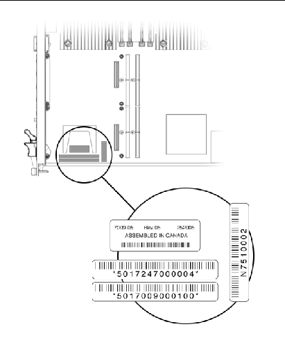
When you call Sun Services, be sure to indicate that the Netra CP3010 board was purchased separately and is not associated with a system. Please have the board identification information ready. For proper identification of the board be prepared to give the representative the board part number, serial number, and date code (see FIGURE 1-6).
1.6.1 Board Part Number, Serial Number, and Revision Number Identification
The Netra CP3010 board part number, serial number, and version can be found on stickers located on the card (see FIGURE 1-6).
The Sun barcode label provides the following information:
- Board part number (for example, 5017247), which is the first seven digits on the barcode label
- Board serial number (for example, 000004), which is the next six digits on the barcode label
The dash/revision/date code label provides the following information:
- Product dash number (for example, -05)
- Revision number (for example, REV: 05)
- Board date code (for example, 252005, which represents the twenty-fifth week of the year 2005)
The MAC address label contains the MAC address for the board in printed and barcode form. See Section 2.4.6, Replacing the EEPROM for information on installation and removal of the MAC address label.
FIGURE 1-6 Netra CP3010 Board Barcode Labeling
|
Note - You might find the labels shown in FIGURE 1-6 on other locations on your board. Also, your particular board configuration might appear different from the preceding illustration.
|
| Netra CP3010 Board User's Guide
|
819-1183-10
|
   
|
Copyright © 2006, Sun Microsystems, Inc. All Rights Reserved.
 CP3010 board is a high-performance single-board computer based on two UltraSPARC® IIIi processors and designed for high availability in a switched network computing environment. This board is compliant with Advanced Telecom Computing Architecture® (ATCA) specifications (PICMG® 3.0 and PICMG 3.1) and can achieve greater performance levels than compactPCI (cPCI) standards-based products targeted for telco markets.


